Published by Electrical Installation Wiki, Chapter M. Power harmonics management – Definition and origin of harmonics
Definition of Harmonics
The presence of harmonics in electrical systems means that current and voltage are distorted and deviate from sinusoidal waveforms.
Harmonic currents are caused by non-linear loads connected to the distribution system. A load is said to be non-linear when the current it draws does not have the same waveform as the supply voltage. The flow of harmonic currents through system impedances in turn creates voltage harmonics, which distort the supply voltage.
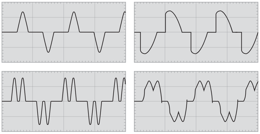
On Figure M1 are presented typical current waveforms for single-phase (top) and three-phase non-linear loads (bottom).
The Fourier theorem states that all non-sinusoidal periodic functions can be represented as the sum of terms (i.e. a series) made up of:
• A sinusoidal term at the fundamental frequency,
• Sinusoidal terms (harmonics) whose frequencies are whole multiples of the fundamental frequency,
• A DC component, where applicable.
The harmonic of order h (commonly referred to as simply the hth harmonic) in a signal is the sinusoidal component with a frequency that is h times the fundamental frequency.
The equation for the harmonic expansion of a periodic function y (t) is presented below:
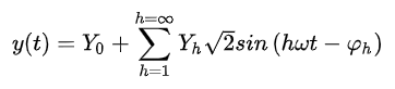
where:
• Y0: value of the DC component, generally zero and considered as such hereinafter,
• Yh: r.m.s. value of the harmonic of order h,
• ω: angular frequency of the fundamental frequency,
• φh: displacement of the harmonic component at t = 0.
Figure M2 shows an example of a current wave affected by harmonic distortion on a 50Hz electrical distribution system. The distorted signal is the sum of a number of superimposed harmonics:
• The value of the fundamental frequency (or first order harmonic) is 50 Hz,
• The 3rd order harmonic has a frequency of 150 Hz,
• The 5th order harmonic has a frequency of 250 Hz,
• Etc…

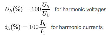
Individual harmonic component (or harmonic component of order h)
The individual harmonic component is defined as the percentage of harmonics for order h with respect to the fundamental. Particularly:
Total Harmonic Distortion (THD)
The Total Harmonic Distortion (THD) is an indicator of the distortion of a signal. It is widely used in Electrical Engineering and Harmonic management in particular.
For a signal y, the THD is defined as:
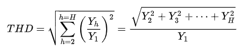
THD is the ratio of the r.m.s. value of all the harmonic components of the signal y, to the fundamental Y1.
H is generally taken equal to 50, but can be limited in most cases to 25.
Note that THD can exceed 1 and is generally expressed as a percentage.
Current or voltage THD
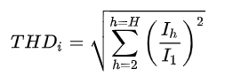
For current harmonics the equation is:
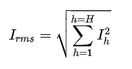
By introducing the total r.m.s value of the current:
we obtain the following relation:
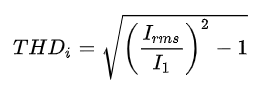
equivalent to:
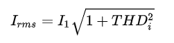
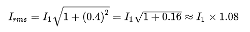
Example: for THDi = 40%, we get:
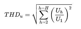
For voltage harmonics, the equation is:
Origin of Harmonics
Harmonic currents
Equipment comprising power electronics circuits are typical non-linear loads and generate harmonic currents. Such loads are increasingly frequent in all industrial, commercial and residential installations and their percentage in overall electrical consumption is growing steadily.
Examples include:
• Industrial equipment (welding machines, arc and induction furnaces, battery chargers),
• Variable Speed Drives for AC or DC motors[1],
• Uninterruptible Power Supplies,
• Office equipment (PCs, printers, servers, etc.),
• Household appliances (TV sets, microwave ovens, fluorescent lighting, light dimmers).
Harmonic voltages
In order to understand the origin of harmonic voltages, let’s consider the simplified diagram on Fig. M3.
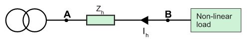
The reactance of a conductor increases as a function of the frequency of the current flowing through the conductor. For each harmonic current (order h), there is therefore an impedance Zh in the supply circuit.
The total system can be split into different circuits:
• One circuit representing the flow of current at the fundamental frequency,
• One circuit representing the flow of harmonic currents.
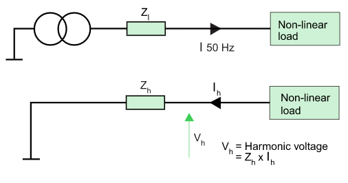
When the harmonic current of order h flows through impedance Zh, it creates a harmonic voltage Uh, where Uh = Zh x Ih (by Ohm’s law).
The voltage at point B is therefore distorted. All devices supplied via point B receive a distorted voltage.
For a given harmonic current, the voltage distortion is proportional to the impedance in the distribution network.
Flow of harmonic currents in distribution networks
The non-linear loads can be considered to inject the harmonic currents upstream into the distribution network, towards the source. The harmonic currents generated by the different loads sum up at the busbar level creating the harmonic distortion.
Because of the different technologies of loads, harmonic currents of the same order are generally not in phase. This diversity effect results in a partial summation.

Notes: 1. to know more about harmonics mitigation related to Variable Speed Drives, please refer to our Schneider Electric White Paper “Choose the best harmonic mitigation solution for your drive”
Author: This Electrical Installation Wiki is a collaborative platform, brought to you by Schneider Electric: our experts are continuously improving its content, collaboration is also open to all.
The Electrical Installation Guide (wiki) has been written for electrical professionals who must design safe and energy efficient electrical installation, in compliance with international standards such as the IEC 60364.
Source URL: https://www.electrical-installation.org/enwiki/Definition_and_origin_of_harmonics
