Published by Burak AKIN, Yıldız Technical University
Abstract. In this paper, efficient PV to PEV’s li–ion battery power transfer is investigated. Dual-interleaved boost topology is applied to the PV to PEV direct power transfer system as DC-DC converter. Proposed dual interleaved boost topology is reached 97 % total efficiency with inversely coupled input boost inductances.
Streszczenie. W artykule opisano metodę transferu energii zed źródła fotowoltaicznego do baterii pojazdu elektrycznego. Zastosowano przekształtnik DC-DC. Osiągnięto 97% sprawności. (Transmisja energii zew źródła fotowoltaicznego do pojazdu elektrycznego)
Keywords: PV – photovoltaic , PEV – plug-in electric vehicle
Słowa kluczowe: bateria słoneczna, pojazd elektryczny
Introduction
It can be difficult to find out grid connected energy, or it is expensive due to first initial costs in rural areas. So, solar power can be a solution as a renewable energy source. For this reason, photovoltaic cell can be used for energy producing from the sun. PV modules can be produced for solar farms by using PV cells. Although PV modules are expensive and relatively low efficient, in near future with the developing technologies it is predicted that the price will be lower and efficiency will be higher. In this paper reliable and high efficient power transfer is investigated from solar power used PV modules to PEV systems.
PEV systems normally demand the related energy from the grid connected energy sources by AC-DC converter. Because the PEV uses high DC voltage li-ion batteries, it is important to use boost converter topology to produce high DC voltage from AC grid with power factor correction (PFC) circuits [1, 2]. However, PV to PEV power transfer has the advantages of direct DC-DC conversion system with boost converter topology without PFC, THDi, reactive power and AC grid interface concerns. Before the efficient power transfer to the PEV system, maximum available power should be consumed from the PV solar energy system.
Solar energy system is renewable but for a limited time effective power source. So, to get high efficiency from the PV to PEV system first maximum power has to be demanded from the PV modules. Maximum power production is possible by controlling the PV modules with maximum power point tracking (MPPT) control systems [3, 4, 5]. This kind of control of the modules can produce the maximum available power instantly. Every switching cycle, efficient DC-DC power transfer charges the li-ion batteries.
MPP is the maximum power of current and voltage rates at one point. MPPT control gets the benefits of the maximum power while daylight condition rapidly changing. There are many cheap and easy MPPT system developed in literature [3, 4, 5]. Some MPPT algorithms are such as perturb and observe, constant voltage, incremental conductance, short circuit pulse, open circuit voltage and temperature method [5].
In this paper the main concern is to get the highest produced power from the PV solar module and transferring it with the highest efficiency to the PEV li-ion battery in standalone solar power system for further energy demand. Also, system complexity and cost problem and dimensions are the other concerns. So after PV cell architecture, PEV li-ion battery should be investigated.
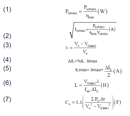
PEV li-ion battery has generally 400 V DC input voltage with approximately 30 kWh energy capacity, so the battery needs efficient and high power charge system. For this reason, CCM working dual interleaved boost converter is investigated. For the calculation, Ii and Vi input current and voltage, Pi and Po input and output power, ηmin predicted minimum efficiency, λ duty rate, ∆IL input current surge, fsw switching frequency, L boost inductance, Vo output voltage and Co output capacitor is represented respectively. The formulas from 1-7 are taken from [2].
For DC-DC power conversion, there is no need for input diode bridge. Furthermore the boost converter has the advantage of direct DC-DC distribution system without PFC, THDi, reactive power and AC grid interface concerns.
Proposed dc-dc dual interleaved boost converter topology
To decide which boost topology should be used in DC-DC power conversion, conventional, dual and interleaved boost topologies are investigated. Conventional boost has the advantage of simply control and few components with efficiency disadvantage. Dual boost topology has the advantage of high efficiency with high THDi and current stresses disadvantage. Interleaved boost has the advantage of high efficiency and low current stress with more components disadvantage.
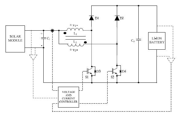
The proposed converter has dual interleaved boost topology to get the benefits of the two converters. To increase the efficiency, inversely coupled inductances are added as boost inductances of the DC-DC dual interleaved boost converter. In Eq. 8 and 9, inversely coupled inductance voltage calculation is represented. In here, L1 and L2 are the main boost inductances and M is the mutual inductance. The proposed converter topology is shown in Fig. 1.

In the proposed topology, L1 and L2 are main boost inductances, S1 and S2 are the main power switches and D1 and D2 are the main power diodes. Solar module and li-ion battery are added as input and output power sources. Ci and Co are the input and output capacitors respectively, D3 and D4 are power switches reverse diodes.
In the proposed converter, because solar module has limited power source maximum efficiency of the system is important. And also, for economical, power density and dimension problems, the converter has to be simple and cheap design with high switching frequency. Dual interleaved boost topology has two branches with 180o phase delay. Steady state waveforms are shown in Fig. 2. Because solar module output voltage is small and li-ion battery input voltage is high enough, duty ratio is generally bigger than 0.5. Efficiency can be improved by adding inversely coupled inductances mutual effect. Also, current stress is lowered by equally shared input power by two boost converter. This proposed converter can be easily adjusted for high power appliances by adding more boost branches and coupled inductances to the system. In this situation control strategy is important for efficient power transfer.

Control strategy
Generally dual interleaved boost controller senses each boost inductances currents with input and output voltage to generate switching signals. However, proposed converter senses input current, input voltage and output voltage to calculate switching signals. Easy and simply control strategy is developed to control the power switches.
Input current and voltage control is important to use PV modules at maximum power point (MPP). In this paper constant voltage MPP is used to control PV modules at MPPT. At a constant input voltage of PV module, input current is controlled to convert maximum power to the PEV li-ion battery with DC-DC dual interleaved converter. Short circuit protection is added to the system to control PV module at MPP.
Output voltage is sensed with input voltage to calculate duty ratio for the dual interleaved boost converter. Also output voltage regulation is added to the control system to prevent excessive voltage to the PEV li-ion battery. To control the system, calculated duty ratio, input current short circuit protection and output voltage regulator are all generates the S1 switching signal. S2 is controlled with 180o phase delay to S1. However to prevent in rush currents to the output capacitor time delay is added to the control system. Also, for steady state conditions input capacitor Ci and output capacitor Co is added to the system with initial values. For high power density and also fast response of the system high switching frequency is important for the control.
Simulation results
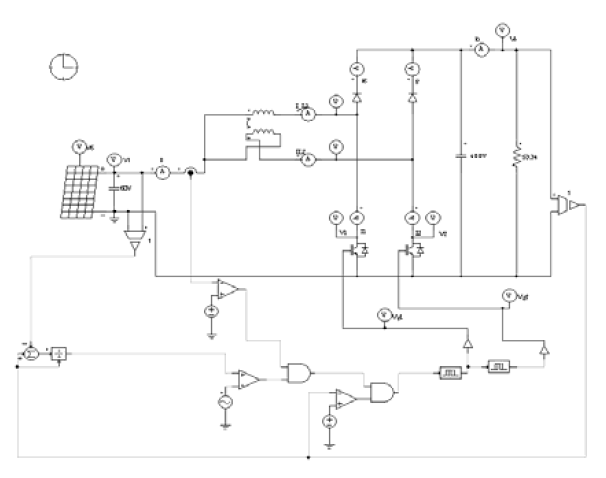
Proposed dual interleaved boost topology POWERSIM circuit schema is shown in Fig. 3 with control circuit. Both interleaved branches working as parallel with 180o phase delay. Control circuit first senses input voltage, input current and output voltage then generates switching signals. First generated signal applied to the first branch power switch S1, afterwards second signal is applied to the second branch power switch S2 with 180o phase delay. As a result both branches shares input current with lower current stress on power switches. Vg1 and Vg2 gating signals is shown in Fig.4 Input current is applied to the inversely coupled inductance to increase the efficiency of the converter.
For steady state response, input capacitor Ci is set to 60V DC and output capacitor Co is set to 400 V DC initial values. All efficiency and other calculations are done according to the steady state condition.
Stand alone solar power system is designed for 3 kW power from beginning to the end resistive load. So, for PV module MPP is set to 60V and 50 A which is for 3 kW maximum power, dual interleaved boost converter is designed for 3 kW output resistive load with 53,34Ω , input and output capacitors are set to 1μ for each watt so 3000μF for total power. PEV li-ion battery has 400V input voltage approximately 30 kWh energy, which is enough at least one week for 3 kWh energy consumption a day.
For better performance, silicone carbide (SIC) semiconductors are used with real specific values in the simulation. S1 and S2 IGBT (IXGH 60N60B2) have lower than 1.8 V saturation voltage with 100 kHz switching capability. Power diodes D1-D2 and reverse power switch diodes D3-D4 (STPSC2006CW) have lower than 1.4 V saturation voltages with better reverse recovery performance.

The proposed dual interleaved DC-DC boost converter has input current short circuit protection and output over voltage protection to provide safety regulations. PV module is controlled by constant voltage MPPT control, so input current short circuit protection is important for the PV system. Also, output over voltage protection is important for the PEV Li-ion battery. PV module output or DC-DC dual interleaved boost converter input current and voltage waveforms are shown in Fig 5 with average measured values.

Output voltage waveform is shown in Fig. 6 for PEV Li-ion battery with measured average values. In here, voltage regulation is 0.8% is calculated.

Steady state waveforms of dual interleaved converter in Fig. 2 are also observed in Fig. 7 from the simulation results.

DC-DC dual interleaved boost converter components S1, S2, L1, L2, D1 and D2 power losses are calculated and it is shown in Fig. 8. Dual interleaved boost converter output power is measured 2911 W and input power is measures 3000 W. As a result, maximum efficiency of the PV to PEV power transfer system is calculated and it is reached 97% value at full load. In Fig 9, efficiency of the converter is shown from 10% to 100% load condition.


Conclusion
PV to PEV efficient power transfer is investigated in this paper with dual interleaved boost converter. Inversely coupled inductances are added as input boost inductance. Each power switch work with 180o phase delay and shares input current with lower stress. Input current, voltage and output voltage are sensed to generate power switch’s gating signals. High performance DC-DC dual interleaved boost converter is applied to the PV to PEV energy transfer system. The proposed converter has 97% efficiency at full load of 3 kW power at 100 kHz switching frequency. Stand alone PV modules can transfer the maximum energy efficiently to PEV systems by proposed converter. This system can be easily improved to upper power levels. After, end user can use PEV li-ion battery as a power source for a house in rural areas.
REFERENCES
[1] Beltrame, F.; Roggia, L.; Schuch, L.; Pinheiro, J.R.; ,“A comparison of high power single-phase power factor correction pre-regulators” 2010 IEEE International Conference on Industrial Technology (ICIT), pp 625-629, May 2010
[2] Akın, B.; Bodur, H.; , “A New Single-Phase Soft-Switching Power Factor Correction Converter,” Power Electronics, IEEE Transactions on , vol.26, no.2, pp.436-443, Feb. 2011
[3] Jaw-Kuen Shiau; Der-Ming Ma; Pin-Ying Yang; Geng-Feng Wang; Jhij Hua Gong; “Design of a Solar Power Management System for an Experimental UAV,” Aerospace and Electronic Systems, IEEE Transactions on , vol.45, no.4, pp.1350-1360, Oct. 2009
[4] Pastre, M.; Krummenacher, F.; Kazanc, O.; Pour, N.K.; Pace, C.; Rigert, S.; Kayal, M.; , “A solar battery charger with maximum power point tracking,” Electronics, Circuits and Systems (ICECS), 2011 18th IEEE International Conference on , vol., no., pp.394-397, 11-14 Dec. 2011
[5] Faranda R., Leva S., “Energy comparison of MPPT techniques for PV Systems”, WSEAS TRANSACTIONS on POWER SYSTEMS, pp 446-455, Issue 6, Volume 3, June 2008
The correspondence e-mail: bakin@yildiz.edu.tr
Source & Publisher Item Identifier: PRZEGLĄD ELEKTROTECHNICZNY, ISSN 0033-2097, R. 89 NR 9/2013
