Published by Tine MARČIČ1, TECES, Research and Development Centre for Electric Machines (1)
Abstract. The paper provides an overview of design problems and contemporary research progress in the currently very interesting field of energy-efficient line-start motors. Discussed are problems related to induction motors (IMs), line-start synchronous reluctance motors and line-start interior permanent magnet synchronous motors (LSIPMSMs). Emphasis is given on small rated power motors, where the LSIPMSM presents the most interesting alternative for replacing IMs widely used in low-cost single-speed drives with ventilator fans, pumps and compressors.
Streszczenie. Artykuł daje przegląd problemów projektowania i postęp we wspólczesnych badaniach w interesującym obszarze wydajności energetycznej silników bezpośredni włączanych. Dyskutowane są problemy związane z silnikami indukcyjnymi, silnikami synchronicznymi reluktancyjnymi z bezpośrednim włączaniem i takie same z magnesem trwałym. Nacisk został położony silniki małej mocy, które skutecznie zastępują silniki indukcyjne w niskokosztowych napędach w wentylatorach, pompach i kompresorach. (Krótki przegląd efektywności energetycznej silników o bezpośrednim włączaniu)
Keywords: computer aided design, induction motors, squirrel cage motors, synchronous motors.
Słowa kluczowe: projektowanie wspomagane komputerowo, silniki indukcyjne, silniki klatkowe, silniki synchroniczne
Introduction
Nowadays, a large share of electric energy is converted into useless heat by electric drives worldwide. A large portion of these electric drives is represented by single-speed applications with ventilator fans, pumps and compressors. In such drives the electric motors are mostly started and fed directly from line, i.e. without the usage of any power electronics. Therefore, the used line-starting motors must fulfil one fundamental requirement – they have to be able to start from standstill and accelerate the complete drive to the rated speed when they are fed from a constant amplitude and constant frequency voltage source, i.e. the so called line-starting capability. And considering the elevated environmental conscience and global market trends, the used motors have to exhibit the highest possible efficiency also. However, these two requirements are quite contradictory when the actual motor design is considered. Therefore the line-start motor design process is connected with adequately addressing many design compromises.
This paper is devoted to providing an overview of the contemporary progress from available literature and own research results in the currently very interesting field of energy-efficient line-start motors.
Overview of line-start motor topologies
The line-start brushless motor family includes induction motors (IMs) [1], line-start synchronous reluctance motors (LSSRMs) [2] and line-start interior permanent magnet synchronous motors (LSIPMSMs) [3]. Their principal rotor structures are depicted in Fig. 1, whereas the stator structures are the same [4, 5].
Motor designers utilize different designs of the squirrel-cage (SC) in all previously mentioned line-start motor types. The SC provides asynchronous starting capability or the so called “line-starting capability” and damping of dynamic oscillations at fast load changes also. In relation to IMs (also called asynchronous motors), the SC is usually made of electrically conducting bars which are embedded in slots of the rotor’s iron core and connected on both ends with cage-end rings. In large motors, the SC can be die-casted or fabricated [6] by using different materials. But in large volume production of small rated power motors the SC is mostly die-casted from aluminium and its alloys. The IM performance both in transient- and steady-state heavily depends on the SC and rotor slot design [7].
The SC in rotors of LSSRMs is usually constructed as electrically conducting material within the LSSRM’s magnetic flux barriers (FBs) [2], which are accountable for the main torque producing component of a LSSRM in its steady-state synchronous operating region. Furthermore, the LSIPMSM has permanent magnets (PMs) inserted in FBs, thus different authors have presented many different SC, FB and PM arrangements within rotors of LSIPMSMs [8-27] along with their design methods. The evolution of these rotor designs has been in line with the evolution of PM materials and their contemporary price and availability [28]. However, the one mostly used SC design in LSIPMSMs is still the one similar to IMs and the nowadays mostly used PM material in LSIPMSMs is of Nd-Fe-B type. The PMs and FBs are accountable for the torque producing components of a LSIPMSM in its steady-state synchronous operating region. Due to the hybrid nature of LSSRMs and LSIPMSMs, the motor designer has to account for all the different torque producing components in both the asynchronous and the synchronous operation region.

Candidates for energy-efficient line-start motors
IMs have been traditionally used in all kinds of applications, mainly due to their low price and robust construction. However, especially for small rated power IMs, their relatively small efficiency and power factor make them inappropriate for markets with strict regulations regarding energy efficiency. Some previous studies were focused on improving the IM efficiency by using expensive cage materials (copper alloys) also in small-sized IMs [1, 29]. The LSSRMs present an alternative only for larger machines because a large portion of rotor material has to be allocated to FBs in order to achieve sufficient torque capability. Thus, LSIPMSMs with buried PMs bellow the SC are currently identified as the most promising design for energy-efficient small rated power applications [30]. Fig. 2 presents a comparison between the measured characteristics of efficiency and power factor and their product for a 1.1 kW four-pole three-phase LSIPMSM and IM with SCs made from aluminium [3]. The efficiency characteristics can be directly compared to measured characteristics of the same rated power IM with the SC made from copper available in [1]. From that comparison it can be seen that LSIPMSMs offer much higher efficiency increase. But on the other hand, for large machines the efficiency increase of LSIPMSMs in comparison to IMs is far from substantial [5].

LSIPMSM torque components
The electromagnetic torque te equation (1) which is part of a LSIPMSM dynamic model written in the d-q reference frame [31] neatly depicts the torque producing components in all line-start motors. In Eq. (1) the subscripts d and q denote variables in the d- and q-axis, respectively; i denotes stator winding currents, ik denotes SC currents, Ls are stator self-inductances, Lm are mutual inductances, Ψm is the length of the PM flux linkage vector, and p is the number of pole pairs.
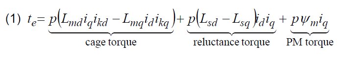
The (asynchronous) cage torque (due to the presence of a SC) influences the LSIPMSM performance in any operation state, where the slip differs from 0. Thus, the cage torque enables line-starting performance and damping of dynamic load oscillations. Apart from the stator winding design, the cage torque depends mainly on the SC design and material.
The synchronous torque components which are represented by the reluctance torque (due to the presence of FBs) and the PM torque (due to the presence of PMs) influence the LSIPMSM performance in any operation state, where the slip differs from 1. In the synchronous operation region (where the slip equals 0) they represent useful torque components. Contrarily, during the line-starting transient they represent braking torques. Thus, they degrade the total torque which should accelerate the LSIPMSM drive up to synchronism. The reluctance torque depends mainly on the design of FBs, which also have to accommodate the used PM segments. The PM torque depends mainly on the placement, dimensions and type of PM material.
For these reasons, the LSIPMSM’s static torque-slip characteristic in the asynchronous operation region is generally lower than the static torque-slip characteristic of a pure IM with the equal SC design, materials, stator and rotor slots geometry and stator winding design. Fig. 3 shows the impact of the aforementioned PM braking torque and the braking reluctance torque on the LSIPMSM’s static torque-slip characteristic [3]. The comparison of measured torque-slip characteristics of a three-phase IM, LSIPMSM and equal LSIPMSM design without PMs in the rotor which actually represents a LSSRM (all with equal SC design) is presented. The difference between the IM torque-slip curve and the LSSRM torque-slip curve at certain slip points represents the reluctance braking torque. And, the difference between the LSSRM torque-slip curve and the LSIPMSM torque-slip curve at certain slip points represents the PM braking torque in the asynchronous operation region.

Design process
As it can be noticed from the previous sections, the design problems of LSSRMs and LSIPMSMs are quite similar and are closely related to IM design problems. And usually the main aim of a new LSSRM or a LSIPMSM design is to replace an existing IM, therefore the new motor has to comply with the following two requirements:
– it has to exhibit line-starting and synchronization capability [2, 16, 20, 32];
– in comparison to the existing IM, it has to exhibit a higher (or at least an equal) torque per unit (stator) current density value and a higher efficiency value in its steady-state synchronous operation region [3].
Different authors have used differently complex approaches in coping with design problems [2, 3, 5, 8-27, 32-35]. Strongly coupled finite element (FE) models [5, 21, 23, 33] are in the author’s opinion computationally too complex to be regularly used by motor designers, thus the design procedure depicted in Fig. 4 has been found to be very useful. It has been founded as a hybrid based on preceding knowledge and experience on design, dynamic modelling and analysis of SC IMs [36-39], (cageless) synchronous reluctance motors [40-44] and (cageless) synchronous PM motors [45-49]. The procedure includes employment of the power balance method based on results from time-stepped FE analyses in the analysis of synchronous performance and employment of lumped parameter dynamic models in the analysis of line-starting performance. The power balance method is employed because FE analyses provide a very detailed image of the geometry and material dependant distribution of magnetic field in the machine region. Thus, the FB design, placement and energy-product of PM material, and their effect on iron core saturation and motor parameters are accounted for in sufficient detail. The employed methods and procedures were described and experimentally validated in [3].

Design considerations
Along with all the aforementioned, the following list presents further important LSIPMSM design aspects, which should be kept in mind by the motor designers in order to achieve target motor performance where a lot of compromises are to be made [3].
– The motors’ line-starting transient depends on the supply voltage [3, 35] and frequency, the drive inertia [23, 33], the characteristic of the mechanical load, and also the starting position of the rotor [23]. The initial rotor position of the LSIPMSM influences its responding current and speed line-starting transient. Its effect is much expressed when the motor is started without any load.
– The compromise between a LSIPMSM’s adequate line-starting performance in the asynchronous operating region and efficiency in the LSIPMSM’s synchronous operating region is connected to the stator winding’s number of turns. Therefore, the number of turns often has to be adopted in accordance with the target load characteristic, especially when rigorous starting conditions are expected.
– The SC material plays a vital role in the electromechanical performance of line-start motors. A higher cage resistance causes that the motor exhibits a higher starting torque value. But on the other hand, the slope of the torque-slip curve near the synchronous speed is lowered. In relation to IMs, this produces an increase of losses and motor temperature and thus the IM efficiency in steady-state is degraded. However, the impact of SC material on LSSRM and LSIPMSM performance may be more severe. When e.g. a LSIPMSM is line – started, the SC should accelerate the complete LSIPMSM drive up to a certain speed and if the acceleration is sufficient the rotor should be pulled into synchronism. Thus, the LSIPMSM’s “pull-in” transient into synchronism depends on the slope of the static torque – slip characteristic of the LSIPMSM near the synchronous speed, and consequently the LSIPMSM’s starting and synchronization capability depends on the used SC material. Results from different studies which can be related to the cage resistance are available in [23, 26, 34, 35].
Economic considerations
LSIPMSMs with buried PMs bellow the SC are currently identified as the most promising design for energy-efficient small rated power applications. However, motor manufacturers tend to be very rigid when it comes to the manufacture of new motor designs because the manufacturing tools (lamination punching, SC die-casting, winding tools, …) always present a substantial part of the motor manufacturing cost. Therefore, especially in high-volume production of small rated power motors (e.g. ventilator, pump and compressor motors) the manufacturers tend to use existing tools until they are worn out or there is a change on the demand side. Enforcement of stricter policies for motor efficiency (like the EU directive 2005/32/EC) is going to force the manufacturers to consider new motor designs as well.
The manner in which LSIPMSM rotors are manufactured (die-casting of SCs at relatively high temperatures, which are higher than the Curie temperatures of PMs) makes the placement of magnetized magnetic segments in the rotor’s FBs impossible before the SC is die-casted. On the other hand, pulse magnetization of the whole multi-pole rotor with buried PMs presents also a problem, because the induced currents of the SC limit the depth of magnetic field penetration in the rotor area and the magnetization homogeneity of magnetic segments as well [50, 51]. Therefore, the easiest way to manufacture a LSIPMSM rotor is by simple purchase and insertion of pre-magnetized PM segments, which may be quite costly.
An economic assessment and overview of the LSIPMSM manufacturing related cost increase and on the other hand the potential electric energy savings by using LSIPMSMs in contrast to IMs is discussed in [30].
But on the other hand and as indicated before, the motor designers can take advantage of both of the synchronous torque components (i.e. a combination of the PM torque and the reluctance torque as well) where by designing higher rotor saliency, less PM material or cheaper PM material can be used in order to achieve sufficient target synchronous performance.
Conclusion
This work presented an integral overview of the line-start motor design related problems. Discussed and pointed out were LSIPMSM design aspects which were related to IM and LSSRM design as well. These comprise the motors’ construction, stator winding design and the arrangement of SC, PMs and FBs in the rotor; and the manufacturing related economic considerations also.
This work was supported in part by the Slovenian Research Agency, Project No. L2-1180.
REFERENCES
[1] Bogl iet t i A. et al., Energy-efficient motors: Comparing the performance of die-cast copper squirrel cage induction motors with aluminum cage induction motors, IEEE Industrial Electronics Magazine, 2 (2008), No. 4, 32-37
[2] Mi l javec D. et al., Rotor-design and on-line starting-performance analysis of a synchronous-reluctance motor, Compel, 28 (2009), No. 3, 570-582
[3] Mar č i č T. et al., Line-starting three- and single-phase interior permanent magnet synchronous motors—direct comparison to induction motors, IEEE Trans. Magn., 44 (2008), No. 11, 4413-4416
[4] Štumberger G. et al., Comparison of capabilities of reluctance synchronous motor and induction motor, J. Magn. Magn. Mater., 304 (2006), e835-e837
[5] Lu Q. F. , Ye Y. Y. , Design and analysis of large capacity line-start permanent-magnet motor, IEEE Tran. Magn., 44 (2008), No. 11, 4417-4420
[6] Craggs J. L., Fabricated aluminum cage construction in large induction motors, IEEE Trans. Ind. Applicat., IA-12 (1976), No. 3, 261-267
[7] Wi l l iamson S. , McClay C. I. , Optimization of the geometry of closed rotor slots for cage induction motors, IEEE Trans. Ind. Applicat., 32 (1996), No. 3, 560-568
[8] Jovanov ski S. B. , Contribution to the theory of asynchronous performance of synchronous machines with salient poles: Part I, IEEE Tran. Power Ap. Syst., PAS-88 (1969), No. 7, 1150-1161
[9] Jovanovski S. B., Hammam M. S. A. A., Contribution to the theory of asynchronous performance of
synchronous machines with salient poles: Part II, IEEE Tran. Power Ap. Syst., PAS-90 (1971), No. 2, 418-426
[10] Honsinger V . B. , Permanent magnet machines: Asychronous operation, IEEE Tran. Power Ap. Syst., PAS-99 (1980), No. 4, 1503-1509
[11] Honsinger V. B., Performance of polyphase permanent magnet machines, IEEE Tran. Power Ap. Syst., PAS-99 (1980), No. 4, 1510-1518
[12] Honsinger V. B., The fields and parameters of interior type AC permanent magnet machines, IEEE Tran. Power Ap. Syst., PAS-101 (1982), No. 4, 867-876
[13] Binns K. J . , Bernard W. R. , Novel design of self-starting synchronous motor, Proceedings of the IEE, 118 (1971), No. 2, 369-372
[14] Binns K. J. et al., Hybrid permanent-magnet synchronous motors, Proceedings of the IEE, 125 (1978), No. 3, 203-208
[15] Binns K. J., Jabbar M. A., High-field self-starting permanent magnet synchronous motor, IEE Proceedings – Electric Power Applications, vol. 128 (1981), No. 3, 157-160
[16] Mi l ler T. J . E. , Synchronization of line-start permanent-magnet AC motors, IEEE Tran. Power Ap. Syst., PAS-103 (1984), No. 7, 1822-1828
[17] Rahman M. A. , Osheiba A. M. , Performance of large line-start permanent magnet synchronous motors, IEEE Tran. Energy Conver., 5 (1990), No. 1, 211-217
[18] Zhou P., Rahman M. A., Jabbar M. A. , Field circuit analysis of permanent magnet synchronous motors, IEEE Tran. Magn., 30 (1994), No. 4, 1350-1359
[19] Rahman M. A. , Zhou P. , Analysis of brushless permanent magnet synchronous motors, IEEE Tran. Ind. Electron., 43 (1996), No. 2, 256-267
[20] Rahman M . A . et al., Synchronization process of line-start permanent magnet synchronous motors, Electr. Mach. Pow. Syst., 25 (1997), No. 6, 577-592
[21] Jabbar M. A., Liu Z., Dong J., Time-stepping finiteelement analysis for the dynamic performance of a permanent magnet synchronous motor, IEEE Tran. Magn., 39 (2003), No.5, 2621-2623
[22] Kurihar a K . et al., Steady-state performance analysis of permanent magnet synchronous motors including space harmonics, IEEE Tran. Magn., 30 (1994), No. 3, 1306-1315
[23] Kur ihara K. , Rahman M. A. , High-efficiency line-start interior permanent-magnet synchronous motors, IEEE Trans. Ind. Appl., 40 (2004), No. 3, 789-796
[24] Abdel-Kader F. M., Osheba S. M., Performance analysis of permanent magnet synchronous motors Part I: Dynamic performance, IEEE Trans. Energy Conver., 5 (1990), No. 2, 366-373
[25] Mi yashi ta K. et al., Development of a high speed 2-pole permanent magnet synchronous motor, IEEE Tran. Power Ap. Syst., PAS-99 (1980), No. 6, 2175-2183
[26] Knight A. M. et al., The design of high-efficiency line-start motors, IEEE Trans. Ind. Appl., 36 (2000), No. 6, 1555-1562
[27] da Silva C. A., Cardoso J. R., Carlson R., Analysis of a three-phase LSPMM by numerical method, IEEE Tran. Magn., 45 (2009), No. 3, 1792-1795
[28]http://www.vacuumschmelze.de/fileadmin/documents/pdf/fipublikationen/2009/NdFeB_Magnets___Properties_and_Applications_revised_13_03_09.pdf {accessed 18th June, 2010}
[29] Parasi l i t i F. et al., Three-phase induction motor efficiency improvements with die-cast copper rotor cage and premium steel, Proceedings SPEEDAM 2004, Capri, Italy, pp. 338-343
[30] I s fahani A. H. , Vaez -Zadeh S. , Line start permanent magnet synchronous motors: Challenges and opportunities, Energy, 34 (2009), 1755-1763
[31] Mar č i č T. et al., Determining parameters of a line-start interior permanent magnet synchronous motor model by the differential evolution, IEEE Trans. Magn., 44 (2008), No. 11, 4385-4388
[32] Honsinger V. B . , Inherently stable reluctance motors having improved performance, IEEE Tran. Power Ap. Syst., PAS-91 (1972), No. 4, 1544-1554
[33] Fei W., Luk P. C. K., Ma J . , Shen J. X. , Yang G., A high-performance line-start permanent magnet synchronous motor amended from a small industrial three-phase induction motor, IEEE Tran. Magn., 45 (2009), No. 10, 4724-4727
[34] Ding T. et al., Design and analysis of different line-start PM synchronous motors for oil-pump applications, IEEE Trans. Magn., 45 (2009), No. 3, pp. 1816-1819.
[35] Peral ta-Sánchez E. , Smi th A. C. , Line-start permanent-magnet machines using a canned rotor, IEEE Trans. Ind. Appl., 45 (2009), No. 3, 903-910
[36] Dolinar D., Štumberger G., Grčar B. , Calculation of the linear induction motor model parameters using finite elements, IEEE Tran. Magn., 34 (1998), No. 5, 3640-3643
[37] Štefanko S., Slemnik B., Zagradišnik I., Stray losses due to inter-bar currents of skewed cage induction motors at no-load, Electr. Eng., 82 (2000), 257-262
[38] Štumberg e r B . et al., Accuracy of iron loss calculation in electrical machines by using different iron loss models, J. Magn. Magn. Mater., 254-255 (2003), 269-271
[39] Štumberg e r B . et al., Accuracy of iron loss estimation in induction motors by using different iron loss models, J. Magn. Magn. Mater., 272-276 (2004), e1723- e1725
[40] Štumberg e r G . et al., Cross magnetization effect on inductances of linear synchronous reluctance motor under load conditions, IEEE Tran. Magn., 37 (2001), No. 5, 3658-3662
[41] Štumberg e r G . et al., Identification of linear synchronous reluctance motor parameters, IEEE Trans. Ind. Appl., 40 (2004), No. 5, 1317-1324
[42] Štumberger G . et al., Nonlinear model of linear synchronous reluctance motor for real time applications, Compel, 23 (2004), No. 1, 316-327
[43] Štumberg e r G . et al., Evaluation of experimental methods for determining the magnetically nonlinear characteristics of electromagnetic devices, IEEE Tran. Magn., 41 (2005), No. 10, 4030-4032
[44] Štumberger G., Štumberger B., Dolinar D., Dynamic two-axis model of a linear synchronous reluctance motor based on current and position-dependent characteristics of flux linkages, J. Magn. Magn. Mater., 304 (2006), e832-e834
[45] Štumberg e r B . et al., Evaluation of saturation and cross-magnetization effects in interior permanent-magnet synchronous motor, IEEE Trans. Ind. Appl., 39 (2003), No. 5, 1264-1271
[46] Štumberg e r B . et al., Torque ripple reduction in exterior-rotor permanent magnet synchronous motor, J. Magn. Magn. Mater., 304 (2006), e826-e828
[47] Hadžiselimovi ć M. et al., Magnetically nonlinear dynamic model of synchronous motor with permanent magnets, J. Magn. Magn. Mater., 316 (2007), e257-e260
[48] Štumberg e r B . et al., Comparison of torque capability of three-phase permanent magnet synchronous motors with different permanent magnet arrangement, J. Magn. Magn. Mater., 316 (2007), e261-e264
[49] Pišek P., Vi r t i č P. , Štumberger B. , Back EMF and torque characteristic of N-N and N-S type of multi-disc axial flux permanent magnet synchronous generator, Przegląd Elektrotechniczny, 84 (2008), No. 12, 221-223
[50] Lee C. K. et al., Analysis of magnetization of magnet in the rotor of line start permanent magnet motor, IEEE Tran. Magn., 39 (2003), No. 3, 1499-1502
[51] Lee C. K., Kwon B. I., Design of post-assembly magnetization system of line start permanent-magnet motors using FEM, IEEE Tran. Magn., 41 (2005), No. 5, 1928-1931
Author: Dr. Tine Marčič, TECES, Research and Development Centre for Electric Machines, Pobreška cesta 20, SI-2000 Maribor, Slovenia, E-mail: tine.marcic@teces.si.
Source & Publisher Item Identifier: PRZEGLĄD ELEKTROTECHNICZNY (Electrical Review), ISSN 0033-2097, R. 87 NR 3/2011
