Published by Dariusz SMUGAŁA(1), Wojciech PIASECKI(1), Magdalena OSTROGÓRSKA(1), Marek FLORKOWSKI(1), Marek FULCZYK(2), Ole GRANHAUG(3),
ABB Sp.z.o.o., Corporate Research Center, Cracow, Poland (1), ABB Oy, Medium Voltage Products, Vaasa, Finland (2), ABB AS, Medium Voltage Products, Skien, Norway (3)
Abstract. Novel protection method of wind turbine transformers against high frequency transients occurring during switchgear operation is described in this paper. Presented results are continuation of research on Very Fast Transients mitigation methods previously published in literature [8]. Principles of novel suppressing device parameters optimization for windmill transformers are also included. ATP-EMTP simulations results for wind farm application were verified by full scale functional tests.
Streszczenie. W artykule przedstawiono nową metodę ochrony transformatorów turbin wiatrowych przed wysokoczęstotliwościowymi przepięciami mogącymi wystąpić w trakcie ich pracy. Przedstawione rezultaty są wynikiem kontynuacji wcześniejszych badań prowadzonych nad ochroną transformatorów dystrybucyjnych przed zakłóceniami o wysokokiej częstotliwości mogącymi wystąpić w sieci SN [8, 9]. Wyniki symulacji przepięć oraz doboru parametrów urządzeń ochronnych, zostały zweryfikowane w trakcie testów funkcjonalnych. (Ochrona transformatorów turbin wiatrowych przed przepięciami wysokoczęstotliwościowymi).
Keywords: high frequency transients, transformers, protection, wind turbines
Słowa kluczowe: przepięcia wysokoczęstotliwościowe, transformatory rozdzielcze, metody ochrony, turbiny wiatrowe.
Introduction and problem definition
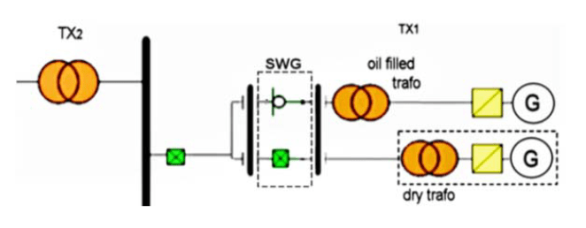
High Frequency (HF) transients influence on wind turbine transformers (especially dry type) has been observed within the research activities presented in this article. They were mainly focused on protection of transformers located at the windmill nacelle. This configuration type is mostly used in practice. Research results presented in this document are study continuation on Fast Transients (FTs) phenomenon overstressing the distribution transformer’s insulation system [2, 4]. Present activities were focused on transients occurrence during normal wind turbine operation [8]. Wind turbines, considering variable operation conditions e.g. wind strength and direction, power network conditions, service, need to be controlled through the breakers operating at relatively high frequency. Presently most of wind turbines, except of air insulated switch-disconnectors, are operated through the Vacuum Circuit Breakers (VCB). Current breaking operations under certain conditions may result in overvoltages generation. During switching operations, interrupters frequently installed into the switchgear (SWG) usually located at the windmill tower bottom, many high frequency transients are generated. In consequence of extremely high voltage steepness (du/dt) occurring e.g. during inductive (e.g. no load) current interruption [3, 5], the insulation system of wind turbine transformers may be overstressed and may lead to pre-mature aging of the insulation material. It may increase transformers failure rate [1, 5, 6]. The high frequency Transient Overvoltages (TOV) problem is dangerous to other connected equipment, e.g. cables and accessories [6]. Generated transients character and overvoltage level depends on wind farm topology and a breaker type. There are two topologies of power network wind turbines connections used in practice (Fig. 1):
– Oil-filled transformer placed at the tower bottom with short connection between the transformer and breaker with long (tens of meters) connection between the transformer and wind turbine with generator,
– Dry-type transformer located at the windmill nacelle with relatively long connection (usually 80÷100 m) with SWG located at the tower bottom.
High frequency transients are generated as a result of relatively short wind turbine cables capacitance (tens of nF, C1,C2 in Fig. 2 and Fig. 3) interaction with low value of dry-type transformer inductance (LT in Fig. 3).
Single windmill power network diagram with dry-type transformer is presented in Fig. 2.

Wind turbine transformer TX1 is connected to the VCB through the cable having capacitance C2. SWG comprising VCB is connected through the cable of C1 capacitance, to the power network connecting point represented by transformer TX2.

Additionally, the following factors in MV networks have an influence on the generated transients level:
– switching in/out power network by operating breaker,
– ground faults,
– pre-strikes and reignitions during switching,
– wave reflections if cable surge impedance do not match the transformer impedance.
The cable capacitance results in generated transients filtering but simultaneously in interaction with transformer inductance, can be a reason for overvoltages and HF transients. They are in particular related with:
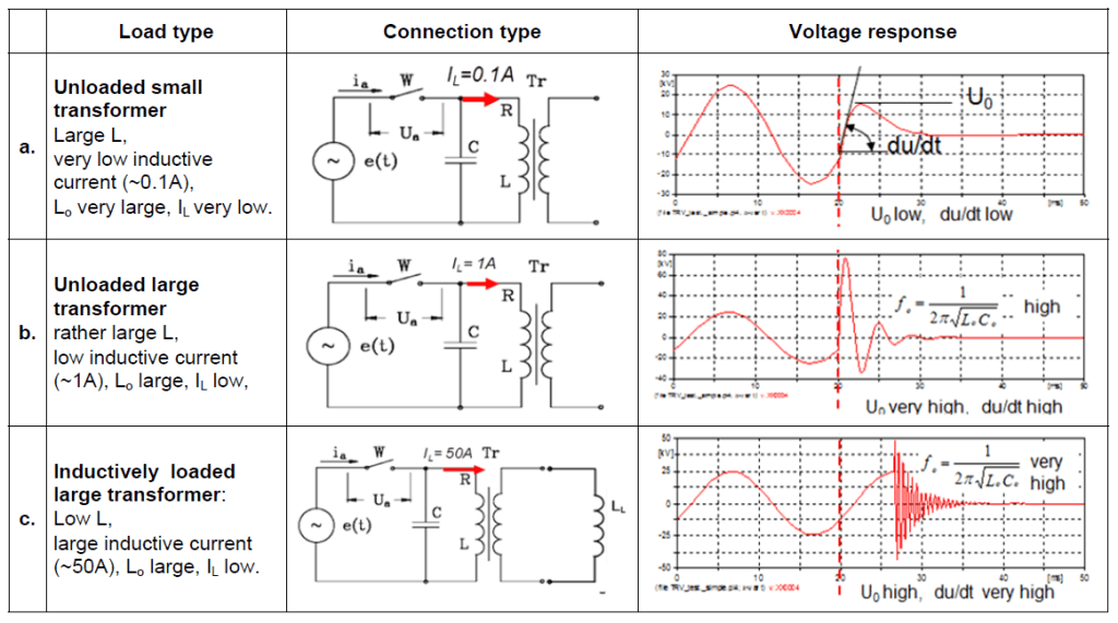
a. Switching-off of an unloaded transformer with high no-load currents values. High natural circuit frequency resulting in fast Transient Recovery Voltage (TRV) build-up,
b. Switching-on a transformer to a high-capacitance line. In this case the input capacitance charging from the network capacitance is limited only in practice by the typically very low line resistance.
Moreover, the HF impedance mismatch between the transformer input and the line result in potential wave reflections, multiplying the overvoltage build-up at the transformer terminals.
The effect of reignition level, number of strikes or voltage steepness mainly depends on circuit parameters e.g. cable parameters, but also on circuit breaker type, transformer size and type, supplying voltage level, resonant frequency value etc.
The main problem in avoiding the VFTs is a low value of the surge impedance due to a low impedance of power cables. There are cases described in literature, of the transformer failures during current breaking (e.g. when the VCBs are used for operation [7]). It is supposed that the HF transients occurring during the switching are the most likely the cause for that.
The problem of very high du/dt is enhanced in the case of short connections to the surge source. Increasing the impedance of the surge source may be achieved by introducing a suppressing series element upstream the protected equipment [9].
Solution
There are several transients problem solutions existing in the market and described in the literature [8] e.g. surge capacitors, RC snubbers, series resistors or surge arresters, however all of them have some weak points. Surge arresters protect power network (e.g. transformers) against overvoltages, but does not provide sufficient protection against high voltage steepness occurring during VCB operation. Capacitors and RC snubbers with typical values of this capacitance (C=0.1μF ÷ 0.5μF) are combined with resistance (R=5Ω ÷ 25Ω) and connected upstream the protected device. However they generally provide sufficient protection but they are characterized by large weight, size and significant costs which typically limits its applicability. These features exclude this solution to locate into relatively small windmill tower space. A potentially applicable lowpass RC filter is not acceptable, due to power dissipation and significant voltage drop.
Therefore a special construction of a series impedance element was developed [5]. The device described in [10] consist of series impedance element, coupled with small (≈10nF) capacitance connected upstream the protected device (transformer). At 50/60Hz the impedance of the element is close to zero, at higher frequencies the impedance has a resistive character (close to cable connection impedance). For the windfarm application where cable connection between the breaker and transformer is present, the cable connection capacitance is utilized. Required capacitance is provided by capacitance of power cable (80÷100m) connection between the SWG and transformer.
Taking into consideration high short circuit current rating of SWG, the original air coil construction developed previously, was replaced by high frequency magnetic material.
Suppressing device concept
The limitations of the presently used mitigation methods led to the development of a new concept of high du/dt mitigation using an impedance choke connected in series [6]. Increasing the impedance of the surge source may be achieved by introducing a series, impedance element upstream the protected transformer, as shown in Fig. 4.
The use of series filter as protecting device is a frequently used method, mostly as common mode chokes in various low voltage systems comprising power electronics.
The choke of appropriately designed frequency characteristic allows significantly increase the voltage wave-front rise time and minimize its influence on the equipment under normal, operating conditions. This means that the choke impedance at 50/60Hz frequency must be close to zero.
To eliminate risk of destroying protection device as result of short circuit current which may occur into the wind turbine power network, previous protective device was redesigned and improved. Concept based on parallel connection of inductor and resistance was replaced by combination of high frequency magnetic material located at the main conductor e.g. cable, coupled with connected in parallel resistance (Fig.5) .
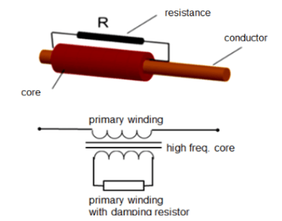
The VFTs suppressing device comprises two windings:
– primary winding made of large cross section conductor (e.g. cable placed within),
– secondary winding with optimized resistance value.
Inductive impedance can be realized by high permeability magnetic cores put on the main conductor e.g. cable. During normal operation when rated current flows through the conductor and for the short circuit current as well, core are saturated so the inductance is negligible.
Tab. 1 Dependence of the voltage escalation process during the inductive current disconnection on the current level [8]
Suppressing device self-resistance is equal to the main conductor resistance (several μΩ).
For the higher frequencies magnetic rings combination provides required inductance so resistance at the secondary winding provides necessary damping.
To optimize the choke parameters for various magnetic cores and resistance connected in parallel, ATP-EMTP simulations were performed. During analysis various cross-section value cores were simulated having material permeability value near to 30 000. It was experimentally verified that cores characterized by this permeability value provides the best saturation characteristic for most often used in practice wind turbine network topologies. Finally the tested chokes equipped with magnetic components having cross-section from 40 cm2 to 120 cm2 were characterized by summary inductance from 0,6 to 1,5 mH and were tested with transformer connected to the VCB through the specific Zcable cable connection impedance.
The simulations were performed in simplified circuit for the “worst case”. Single re-ignition during VCB operation were treated, for the simulation needs, as voltage step with the magnitude equal the highest system voltage amplitude (in this case 29 kV).
Figures (Fig.6÷Fig.7) presents selected choke current simulation results for various damping resistance values (R1÷R8) and various cores cross-sections. Choke current simultaneously represents choke core saturation occurrence.

The figure below presents the voltage at the transformer when the step voltage is applied for various resistor values.
Performed simulations indicated that, the best performance is achieved when the resistor value is close to cable wave impedance – Zcable.

Damping resistance should be calculated to provide the best suppressing effectiveness. Voltage at the transformer terminal was taken as the criterion for proper resistance value calculation (Fig.8). Calculation results [8] confirmed the best performance of suppressing device is achieved for resistor value near to cable surge impedance.
The optimal protection provides combination of the choke with additional small capacitor. Especially for the case when the transformer is connected to the circuit-breaker through the short cable characterized by small cable surge impedance.
Functional tests results
New concept of VFT suppressing device functional tests were performed for typical single wind turbine circuit (Fig.1, Fig.2).
Tests stand comprised the following components:
– 630A rated current Ring Main Unit (RMU) equipped with 24 kV VCB,
– 3×80 m single phase, 25 mm2 cross-section cable with 33 mH/km inductance and 150 nF/km capacitance
– 630 kVA transformer – In Yy 24 kV / 0.24 kV
– 3x suppressing devices located between the RMU and transformer (Fig.4)
Tests were performed for various chokes configurations (various resistance and core cross-sections values):
a. base case, no suppression devices,
b. 40 cm2, 70 cm2 and 120 cm2 cores cross-section
c. Various dumping resistance values from 0.7xZcable to 6xZcable (alternatively no resistor connected) for each version of choke core cross-section
Base case – no active chokes connected
In the base case there were no active chokes connected into power network.


The experimental results confirmed the applicability of the series-choke protection concept to mitigate high frequency and high du/dt transients.
In cases when the transformer internal capacitance is low, what corresponds to dry-type transformers case, additional small surge capacitor plays an important role in the transients suppression. It has to be pointed out, that the value of the capacitance used was more than an order of magnitude smaller, than typical the value of the typical snubber’s capacitor.
Conclusions
A new mitigation method against high du/dt overvoltage hazards in a form of a series-connected choke element was developed. It was demonstrated that the use of the choke significantly reduces voltage steepness and number of reignitions generated during transformer operated through the breakers. Additionally noticeable overvoltage reduction was observed.
The use of appropriately designed series choke device can:
• Limit the du/dt values at transformer terminals
• Limit transient overvoltage
• Eliminate wave reflections in cable and HF oscillations (when Zchoke = Zcable)
• Eliminate or reduce the number of re-ignitions (requires C in order to lower oscillation frequency
The problem of potential VFT-related hazard to transformer and other power equipment resulted from switching operations was demonstrated in a practical case. The number of pre-strikes during contact making was reduced and high frequency oscillations were practically eliminated.
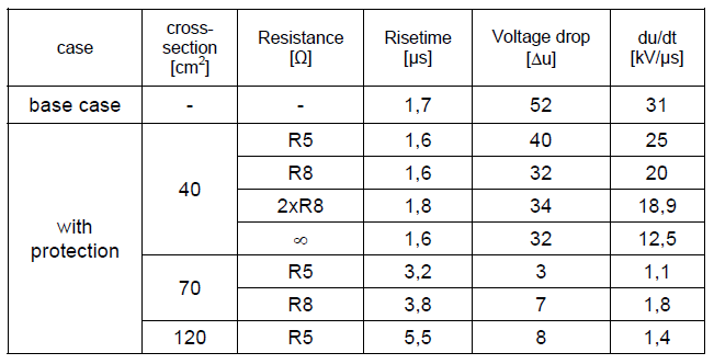
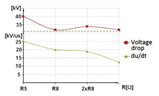
High du/dt was over 2x reduced with the use of the chokes only. Further reduction was achieved when a small (10nF) surge capacitors were used. Prototypes of chokes were experimentally tested and confirmed the applicability of the series-choke protection concept to mitigating high du/dt transients resulting e.g. from the VCB switching operations. The resistor value should provide the best suppressing effectiveness. The voltage at the transformer terminal was taken as the criterion. Simulation results demonstrated that the best performance of suppressing device is achieved for resistor value close to cable surge impedance The parameters of the recorded during the tests transients were presented in Tab. 2 and Fig 16.
Tab. 2. Average du/dt values observed during tests
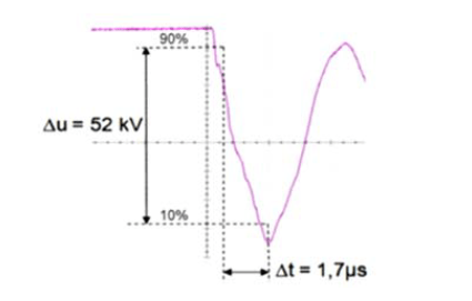
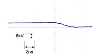
When chokes are inactive and no suppressing device is connected before transformer voltage steepness is few tens of kilovolts per microsecond.
Connecting chokes with larger core cross-section, results both in the voltage steepness reduction and the overvoltage peaks suppression. For relatively large permeability cores with cross-section (40 cm2), du/dt reduction is insignificant then for cross-section larger (70 ÷ 120 cm2) du/dt reduction is very high (up to 10x).
For all tested chokes high degree of oscillation reduction is observed during breaking, especially when additional suppressing resistor is connected at the secondary winding.
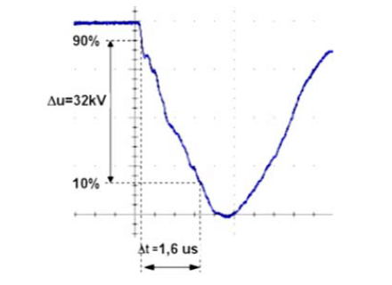
Performed experiments demonstrated that, despite that the risetimes of the waveforms observed at the transformer terminals for the base case (with no protection) were relatively long due to the experiment set-up limitations, a significant reduction in the transients amplitudes was observed. Especially, when an appropriate combination of core parameters and the resistance value was applied.
REFERENCES
[1] CIGRE working group A2-A3-B3.21, Electrical Environment of Transformers; Impact of fast transients”, ELECTRA 208, (2005)
[2] Lopez–Roldan J., De Herdt H., Min J., Van Velthove R., Decklerq J., Sels T., Karas J., Van Dommelen D., Popow P., Van der Sluis L., Aquado M., Study of interaction between
distribution transformer and vacuum circuit breaker, Proceedings of 13th ISH (2003), pp. 62÷64
[3] Popov M., Acha E., Overvoltages due to switching off an unloaded transformer with a vacuum circuit breaker, IEEE Trans. on Power Delivery, Vol. 14, No. 4, (1999), pp. 1317÷1322
[4] Burrage L. M., Shaw J. H., McConnell B. W., Distribution transformer performance when subjected to steep front impulses, IEEE Trans. on Power Delivery, Vol. 5, No. 2, (1990)
[5] Piasecki W., Bywalec G., Florkowski M., Fulczyk M., Furgal J., New approach towards Very Fast Transients suppression, Proceedings of IPST’2007
[6] Paul D., Failure Analysis of Dry-Type Power Transformer, IEEE Transaction on Industry Applications, Vol. 37, No. 3, (2001)
[7] Wong S. M., Snider L. A., Lo E. W. C., Overvoltages and reignition behavior of vacuum circuit breaker, Proceedings of IPST’2003
[8] Smugała D., Piasecki W. , Ostrogórska M., Florkowski M., Fulczyk M., Kłys P., Distribution transformers protection against High Frequency Switching Transients, PRZEGLĄD ELEKTROTECHNICZNY (Electrical Review), ISSN 0033-2097, R. 88 NR 5a/2012
[9] Florkowski M.,Fulczyk M.,Ostrogórska M., Piasecki W., Steepness reduction of ultra-fast chopped surges at transformer terminal, ICHVE (2012), pp.145÷149
Authors/Autorzy:
Dariusz Smugała, PhD. Eng., E-mail: dariusz.smugala@pl.abb.com
Magdalena Ostrogórska, MsC.Eng. E-mail: magdalena.ostrogorska@pl.abb.com
Wojciech Piasecki, PhD.Eng., E-mail: wojciech.piasecki@pl.abb.com
Marek Florkowski, PhD,DSc.,Eng E-mail: marek.florkowski@pl.abb.com
ABB Corporate Research Center, Starowislna 13 A Str., 31-038 Cracow, Poland,
Marek Fulczyk, PhD.Eng. E-mail: marek.fulczyk@pl.abb.com
Muottitie 2, 65100 Vaasa, Finland
Ole Granhaug, MSc.Eng. E-mail: ole.granhaug@no.abb.com
ABB AS Amtm. Aallsgate 73, P.O. Box 108 Sentrum, 3717, Norway
Source & Publisher Item Identifier: PRZEGLĄD ELEKTROTECHNICZNY, ISSN 0033-2097, R. 89 NR 10/2013
