Published by Electrotek Concepts, Inc., PQSoft Case Study: Harmonic Current Cancellation Evaluation, Document ID: PQS1002, Date: March 15, 2010.
Abstract: Utility power system harmonic problems can often be solved using a comprehensive approach including site surveys, harmonic measurements, and computer simulations.
This case study presents the results for a customer step-down transformer harmonic current cancellation evaluation. The analysis was completed using the SuperHarm program. The simulation results show the reduction of the customer primary harmonic current distortion level due to the phase shifting caused by the different step-down transformer connections.
INTRODUCTION
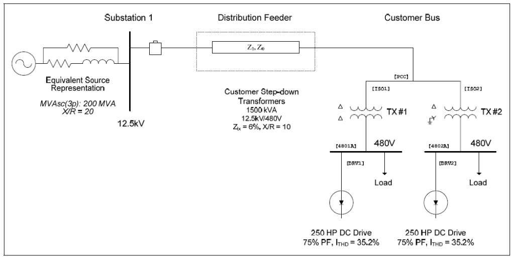
A harmonic current cancellation evaluation was completed for the system shown in Figure 1. The case study was completed using the SuperHarm program. The accuracy of the simulation model was verified using three-phase and single-line-to-ground fault currents and other steady-state quantities.
Isolation transformers can be used with multiple nonlinear loads to create an effective twelve-pulse operation. In an actual twelve-pulse configuration, the front-end rectifier circuit uses twelve diodes instead of six. When properly designed, this configuration practically eliminates the 5th and 7th harmonics. The disadvantages of this design are cost and construction due to the requirement for either a delta-delta/delta-wye transformer pair, or a three-winding transformer to accomplish the 30° phase shifting necessary for proper operation. This configuration also affects the overall drive system efficiency rating because of the voltage drop associated with the transformer requirement.
One possible harmonic current cancellation method is to use a pseudo twelve-pulse configuration that can be achieved by supplying one adjustable-speed drive through a delta-wye connected transformer, and another drive through a delta-delta connected transformer. When the two waveforms are combined on the primary, the resulting waveform injected into the utility system has a much lower current distortion value, primarily because the 5th and 7th harmonics nearly cancel.
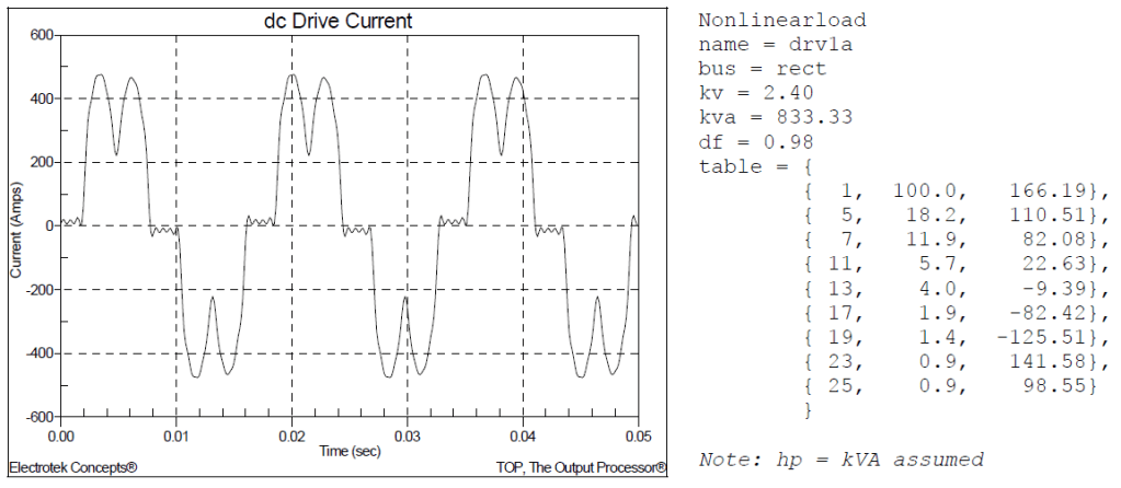
For effective cancellation to occur, the customer nonlinear loads must be operated simultaneously and have similar characteristics. This is true for the system shown in Figure 1 where multiple adjustable-speed drives are being operated in pairs. Figure 2 shows the simulated current waveform and harmonic spectrum (single phase shown) for the 250 hp, 480 volt dc drive running at full load and 75% power factor. The current has a fundamental frequency value of 297 amps, an rms value of 315 amps, and a THD value of 35.2%. The utility source impedance may be approximated using the following expression:
XSC ≈ kVφφ2 / MVA3φ = 12.52 / 200 = 0.781Ω
where:
kVφφ = system rms phase-to-phase voltage (kV)
MVA3φ = three-phase short circuit capacity (MVA)
XSC = system short circuit reactance (Ω)
SIMULATION RESULTS
This case study evaluates the effect of applying transformers with different connections to determine the harmonic current distortion levels on both the primary and secondary sides of the customer transformers. Case #1 involved two delta/delta transformers. Case #2 involved one delta/delta and one delta/wye transformer. Case #3 involved two delta/wye transformers. The simulation results are summarized in Table 1. The results show that the only case that achieves the harmonic cancellation is Case #2, which includes the required 30-degree phase shift introduced by the delta/delta, delta/wye configuration.
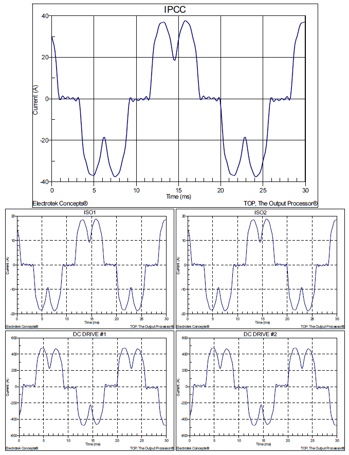
Figure 3 shows the simulation results for Case #1, where the current distortion on the primary of the customer transformer is not reduced due to the harmonic current cancellation.
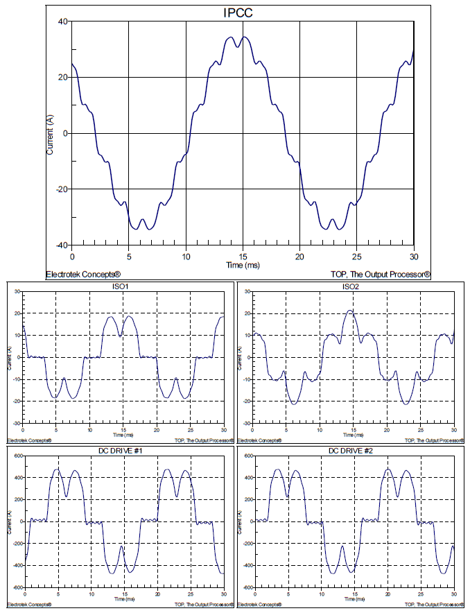
Figure 4 shows the simulation results for the Case #2, which is the mitigation solution case highlighting the effect of the 30-degreee phase shift.
Table 1 – Summary of Simulation Results for the Harmonic Cancellation Evaluation
| Case # | TX #1 | TX #2 | IPCC | IISO1 | IISO2 |
|---|---|---|---|---|---|
| 1 | Δ Δ | Δ Δ | 33.8% | 33.8% | 33.8% |
| 2 | Δ Δ | Δ Y | 8.9% | 33.8% | 33.8% |
| 3 | Δ Y | Δ Y | 33.8% | 33.8% | 33.8% |
SUMMARY
This case study summarizes the results for a customer step-down transformer harmonic current cancellation evaluation. The results show the reduction of the customer primary harmonic current distortion level due to the phase shifting caused by the different transformer connections.
REFERENCES
1. Power System Harmonics, IEEE Tutorial Course, 84 EH0221-2-PWR, 1984.
2. IEEE Recommended Practice for Monitoring Electric Power Quality,” IEEE Std. 1159-1995, IEEE, October 1995, ISBN: 1-55937-549-3.
3. IEEE Recommended Practices and Requirements for Harmonic Control in Electrical Power Systems, IEEE Std. 519-1992, IEEE, ISBN: 1-5593-7239-7.
RELATED STANDARDS
IEEE Std. 519-1992
IEEE Std. 1159-1995
GLOSSARY AND ACRONYMS
ASD: Adjustable-Speed Drive
CF: Crest Factor
DPF: Displacement Power Factor
PF: Power Factor
PWM: Pulse Width Modulation
THD: Total Harmonic Distortion
TPF: True Power Factor
