Published by Krzysztof PRZYSTUPA1, Lublin University of Technology (1)
Abstract. The article discusses the problem of the widespread use of devices that require increased quality electric power supply. An example of a practical division of electricity receipts into several categories is shown. Methods of increasing the reliability of power supply are described and the most commonly used technical solutions for this purpose are discussed.
Streszczenie. W artykule omówiono problem powszechnego występowania urządzeń, które wymagają zasilania o podwyższonej jakości dostaw energii elektrycznej. Pokazano przykład praktycznego podziału odbiorów energii elektrycznej na kilka kategorii. Opisano metody zwiększenia niezawodności zasilania oraz omówiono najczęściej stosowane w tym celu rozwiązania techniczne. Wybrane metody poprawy niezawodności zasilania
Keywords: power negativity, power quality, Uninterruptible Power Supply (UPS)
Słowa kluczowe: niezawodność zasilania, jakość zasilania, zasilacz bezprzerwowy (UPS)
Introduction
There are many types of electricity receivers that require continuous and almost ideal power supply. Despite the fact that the degree of power supply reliability in the power system is very high, IT equipment, data processing and transmission equipment, precise control units and control of long-term industrial processes are sensitive to various types of interference that may occur in the power grid. The scale of the problem is also shown by the fact that the requirements for the power quality are important for different receivers: on the one hand, it can be medical equipment, and on the other, ordinary LED lighting [1].
Phenomena disrupting energy supply not only cause deterioration of power quality in the sense defined by ISO 9000 series standards but also affect the durability of devices, their lifetime and reliability. Poor power quality also has an adverse effect on the quality of products manufactured with sensitive devices. An example may be the quality of the produced light, errors in data transmission or the quality of the surface worked in the milling process. For correct operation of the described devices, it is necessary to use guaranteed electric power supply systems, both AC and DC [2-4].
Different requirements as to the reliability of the power supply resulted in the development of recipients’ classification. The main division concerns two groups: industrial recipients and municipal recipients. It has been assumed that there are three categories of recipients in the group of industrial recipients:
• Category I – with the highest requirements (highest reliability of power supply). These are devices whose failure may cause a threat to human life or very serious material losses.
• Category II – with increased requirements regarding the quality and reliability of power supply. These are devices whose failure causes losses in production.
• Category III – with no special requirements. These are other devices not classified in categories I or II.
When designing the power system for devices of category I, it is necessary to take into account the detailed requirements of individual devices and, without using a relatively adequate back-up power supply system, which must be independent of the basic power supply. In the case of the third category, sometimes the back-up systems are also used, but only when it is economically justified. The described division results from project findings and it is not directly related to the applicable law. It should be noted that the categorization of devices is very often related to the structure of the external power grid and distribution network inside the plant.
In practice, the technical capabilities of the local electricity supplier (distribution company) are very important and decisive.
Municipal recipients, i.e. recipients supplied from public distribution networks usually with a voltage of up to 1kV, are non-industrial recipients with public facilities (residential buildings, banks and hospital buildings with some exceptions, offices, railway facilities, aviation objects, commercial facilities, etc.). This group is sometimes also divided into three or four categories.
In category I with the highest priority power supply, the recipients require uninterruptible power supply or have devices in the case of which the power supply must be reliable. The applied solutions consist in using uninterruptible power supply from a back-up source, e.g. power generator adapted for long-lasting work. This solution is used for hospital operating rooms, banking computer systems, etc.
In category II with a high priority supply power, breaks should not exceed 1 second. For this purpose, for example, two independent power lines from the energy system are used. Entities belonging to this group are: hospitals, radio stations, railway stations and equipment, airports, etc.
In category III with a medium power supply priority, breaks should not exceed several seconds. The solutions applied mainly concern emergency lighting as well as numerically controlled elements and devices. The problem is solved by power generators. The energy consumers in this group are, for example, large residential buildings, large office buildings, and sometimes road infrastructure elements.
In the last IV category there are no additional requirements as to the reliability of power supply. Relatively long power interruptions lasting even many minutes are allowed. Typical objects in this category are single-family houses in rural areas, houses in sparse urban buildings, blocks of flats etc. Most often, these objects are powered by a single radial line.
The presented division, similarly as in the case of industrial recipients, is not legally defined, but it rather results from design practice and distribution companies [5].
Increased reliability of power supply
Increasing the reliability of power supply can be obtained through various financial investments, with the increase in reliability being determined by the exponential function.
This makes it necessary to choose a reasonable investment, which should be determined by considering the required parameters, which include:
The power of the source and the maximum time to deliver energy.
• Switchover time, i.e. the time from the moment of voltage decay on the basic source until the load is supplied from the back-up source. Yet, this time is often extended by the time of decreasing the power quality and the time of returning to the appropriate minimum level of power quality.
• Efficiency of the applied solution.
• Maintenance cost both during work and stand-by.
An ideal alternative source of back-up power should meet the following requirements:
• Unlimited source of energy, i.e. high power.
• Unlimited working time.
• Zero changeover time.
• Low operating costs during operation.
• Zero operating costs while waiting.
Unfortunately, practical solutions do not have such parameters. Table 1 presents the most common practical solutions for back-up power supply and their feature
Table 1. Backup power supply devices and their parameters
| Type of supply | Source power | Changeover time | Installation costs |
|---|---|---|---|
| Additional power line from the grid | Unlimited | From milliseconds to seconds | Very high |
| Power generator | Nearly unlimited | From a few seconds to a few minutes (rarely less than a second) | From medium to high |
| Batteries | Usually low, Rarely medium, Occasionally high. | From a few seconds to nearly seamless | Low or medium |
| Uninterruptible power supply (UPS) | From low to high. Rarely low. | From less than a second to nearly seamless | From medium to high |
According to Table 1, recipients with increased requirements for energy quality and reliability of its supply should be supplied from at least two power lines. Such a power supply requires the use of ATS automatics – automatic switching on of the reserve. This solution is the most expensive, but at the same time provides unlimited power supplies. An alternative to using power from the second power line is the use of a power generator. In this case, the investment costs are much lower than those related to the construction of the power line but the delivered power drops significantly. The time required to start the unit can also be extended. This solution also requires ATS automation and complex automation to control the operation of the unit. The use of the generator may be the third route of energy supply in the case of particularly demanding customers (two power lines and generator), such a solution greatly increases the reliability of energy supplies but increases the possibility of extending the total time of reserve power supply [6].
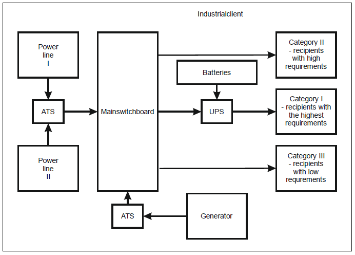
In case of recipients using important IT systems, local computer networks, microprocessor devices controlling complex technological processes, UPS uninterruptible power supplies are used. They provide an almost reliable power supply, with low power, in a relatively long time with a very short switching time of the power source. UPS devices in the internal structure have ASS automatics. Fig.1 shows an example of a customer supply system with increased requirements for power reliability [7-9].
Two-sided power supply
The two-sided power supply from the power grid is implemented from two independent main power points, so-called MSP (main supply point). It can be implemented using high voltage (HV) networks, medium voltage (MV) networks and sometimes even low voltage (LV) networks.
Generators
There are four groups of power generators:
• In the first group there are generators that are switched on manually after power supply decay. The power of these generators is from several dozen KW to several MW. The time of readiness for loading depends on the power and ranges from 5-15 seconds for small devices up to 3-4 minutes for the largest devices.
• In the second group there are devices with powers similar to those of the first group, but these are devices equipped with electronics enabling automatic start. This solution significantly shortens the time of preparing the device for load.
• In the third group there are devices equipped with a flywheel (constantly rotating mass). The second characteristic feature of these devices is equipping them with the most frequently controlled electronic clutch. Aggregates of this group work according to the following algorithm: an electric motor powered from the basic power line continuously drives the flywheel on the common shaft with an electric generator. However, the generator does not work because it is disconnected by the clutch. In the event of a failure, the clutch is switched and the generator starts producing energy. During the nominal operation of the generator, the drive is carried out by combustion engines. In the group of these devices there are those in which the generator operates in the idle state and after the supply voltage decays, the generator goes into the rated operating state. The spinning mass provides the necessary energy for a period of time from the power supply failure until the generator’s generator drive is fully started.
• In the fourth group there are devices of similar construction to those from the third group, with the generator working in them continuously supplying selected important devices. At the moment of the power supply decay, the generator load is increased by attaching additional receivers.
Batteries
In industrial practice, two types of systems are used in which the batteries work [10]:
• In the normal operating condition of the supply network, the batteries are constantly recharged. In the event of a failure of the basic power supply, the battery is switched on. This system is used to power the so-called own needs, e.g. telephone switchboard, power supply for DC receivers, as well as receivers that can be powered by both direct and alternating current, e.g. emergency lighting.
• In the second system there is a much larger rectifier that simultaneously recharges the batteries and supplies the load. It is only in the event of an emergency that the energy consumption from the batteries is started. The system of such work has features characteristic for uninterruptible power supplies.
Uninterruptible Power Supply (UPS)
Uninterruptible Power Supply UPS units are intended for supplying loads with the highest quality requirements, and especially for power supply continuity [11-14]. In industrial practice there are three basic types of UPS:
• Passive readiness (VFD class sometimes referred to as off-line).
• Double conversion (VFI class sometimes referred to as on-line).
• Interactive line (class VI sometimes referred to as hybrid).
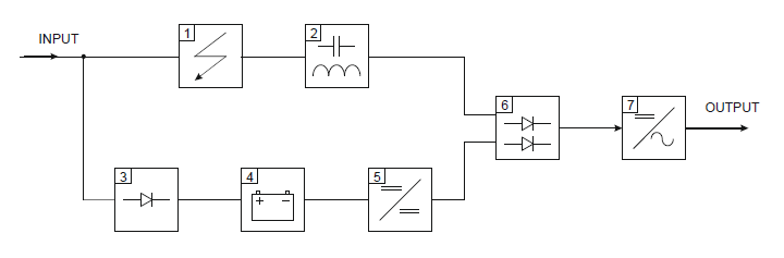
Off-line systems charge the battery during normal operation of the basic power supply. At the moment of the failure of the basic power supply, the inverter is started, which draws energy from the batteries providing the necessary power supply to the receivers (Fig. 2). In off-line power supplies, the primary power source is the power grid. The backup power source is batteries, or less often their sets. In simplified terms, it can be said that the off-line power supply “does nothing” until a power failure occurs. This failure does not have to involve a power failure. It may also be a change in amplitude or frequency. The operation of the switch (6 fig. 2) depends on the electronic logic used.
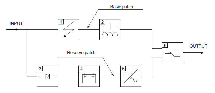
(1 – surge suppressor, 2 – filter, 3 – battery charging system, 4 – battery, 5 – DC/AC converter, 6 – switch)
The relatively long time of switching paths from primary to standby is a fundamental disadvantage of VFD (off-line) power supplies.
On-line systems are based on a complete idea from separating the receiver from the power grid (Fig. 3). The energy taken from the network is used only for charging the battery. The power supply is supplied from the energy accumulated in the battery through the inverter.
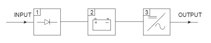
(1 – battery charging system, 2 – battery, 3 – DC/AC converter)
On-line UPS can be implemented using two paths similar to off-line devices (Figure 4)
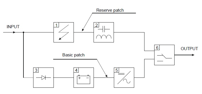
(1 – surge suppressor, 2 – filter, 3 – battery charging system, 4 – battery, 5 – DC/AC converter, 6 – switch)
Theoretically, a completely smooth and imperceptible transition of the receiver from the basic power supply to the standby power supply is the key advantage of the VFI (online) power supplies. The second advantageous feature of this type of power supplies is the possibility of the receiver working with the frequency of the supply voltage other than the frequency of charging the battery system.
Linear interactive UPSs work in such a way that during normal operation of the basic power part of the energy is consumed permanently recharging the battery. At the same time, some of the battery energy continuously goes to the receiver. In this solution, there is a constant power backup for the primary energy backup (Fig.5 and Fig. 6).

(1 – surge suppressor, 2 – filter, 3 – battery charging system, 4 – battery, 5 – DC/DC converter, 6 – transformer, 7 – DC/AC converter)
The main part of the solution shown in Fig.5. is a transformer with three windings (6). Two of them constitute a classical network transformer and the third winding placed on the primary side has a control and intervention role. In its circuit there is a battery and DC/AC converter or an electronic system that works in one direction as an inverter and in the opposite direction as a rectifier. This winding is used to introduce corrective energy in the moments of loss of basic power supply or energy reception when there is too much of it. In the event of a power failure, the auxiliary winding takes over the whole task of supplying energy.
In the situation of power supply of devices that do not allow disturbances in the shape and frequency of power supply, systems similar to the solution proposed in Fig. 6 are used.
(1 – surge suppressor, 2 – filter, 3 – battery charging system, 4 – battery, 5 – DC/DC converter, 6 – semiconductor driver, 7 – DC/AC converter)
The inverter (5 -Fig.6) in the state of waiting for power failures does not work. It is launched when it is detected. The battery charging system (3 -Fig.6.) is small because it works only for the needs of the battery. This type of power supply does not show or has a very low switching time. The last group of devices used to improve the reliability of power supply are non-conventional devices. We include devices using super capacitors, flywheels and superconducting magnetic energy storage (SMES) [15].
REFERENCES
[1] Arrillaga J., Neville R., Watson S., and Chen S., Power system quality assessment. Chichester, England: John Wiley & Sons, 2000.
[2] Bollen M. H. & Bollen M. H., Understanding power quality problems: voltage sags and interruptions. Vol. 445. New York: IEEE press, 2000.
[3] Arrilaga J., Watson N. R., Chen S., Power system quality assessment. John Wiley & Sons, Chichester, New York, Weinheim, Brisbane, Singapore, Toronto, 2000.
[4] Barlik R., Nowak M., Jakość energii elektrycznej-stan obecny i perspektywy. Przegląd Elektrotechniczny, 2005, 81: 1-12.
[5] Klajn A., Markiewicz H., Jakość energii i nie zawodność zasilania w instalacjach elektrycznych. Dodatek do miesięcznika INPE, Zeszyt 14, marzec 2017.
[6] Siwy, E., Witek B., Wybrane zagadnienia technicznej realizacji koncepcji Smart Grid w kontekście jakości zasilania z sieci z generacją rozproszoną. Przegląd Elektrotechniczny 88.8 (2012): 116-119.
[7] Dołęga W., Układy zasilania zakładów przemysłowych w aspekcie niezawodności i pewności dostawy energii elektrycznej. Mechanizacja i automatyzacja górnictwa 49 (2011): 23-26.
[8] Sutkowski T., Rezerwowe i bezprzerwowe zasilanie w energię elektryczną-urządzenia i układy. Stowarzyszenie Elektryków Polskich. Centralny Ośrodek Szkolenia i Wydawnictw, 2007.
[9] Martyniak T., Nawrocki J., Antończyk B., Optymalizacja doboru agregatów prądotwórczych oraz wytyczne ich zabudowy w pojazdach specjalnych, Szybkobieżne Pojazdy Gąsienicowe 1 (2005).
[10] Wiatr J., Miegoń M., Zasilacze UPS oraz baterie akumulatorów w układach zasilania gwarantowanego. Dom Wydawniczy MEDIUM, 2008.
[11] PN-EN 62040, Systemy bezprzerwowego zasilania (UPS).
[12] Lasseter R. H., Eto J. H., Schenkman B., Stevens J., Vollkommer H., Klapp D., Linton E., Hurtado H., Roy J., CERTS microgrid laboratory test Bed, IEEE Transactions on Power Delivery, 26 (1), art. no. 5673682, pp. 325-332. 2011.
[13] Lasseter R.H., Smart distribution: Coupled microgrids, Proceedings of the IEEE, 99 (6), art. no. 5768104, pp. 1074-1082, 2011.
[14] Aamir M., Mekhilef S., An Online Transformerless Uninterruptible Power Supply (UPS) System with a Smaller Battery Bank for Low-Power Applications, IEEE Transactions on Power Electronics, 32 (1), art. no. 7428955, pp. 233-247, 2017.
[15] Cieśla A., Skowron M., Pole magnetyczne jako źródło energii w nadprzewodnikowych zasobnikach energii. Przegląd Elektrotechniczny 94 (2018).
Authors: Krzysztof Przystupa, PhD, Eng. Politechnika Lubelska, Wydział Mechaniczny, Katedra Automatyzacji, ul. Nadbystrzycka 36, 20-618 Lublin, E-mail: k.przystupa@pollub.pl
Source & Publisher Item Identifier: PRZEGLĄD ELEKTROTECHNICZNY, ISSN 0033-2097, R. 94 NR 12/2018. doi:10.15199/48.2018.12.62
