Published by Andrzej ŁEBKOWSKI, Gdynia Maritime University, Department of Ship Automation
Abstract. The paper presents the results of temperature and short-circuit research of battery types most commonly used in electric vehicles. Basing on performed tests, the plots of changing internal resistance of lead-acid and lithium batteries are shown. On the basis of conducted short-circuit experiments of selected lithium based batteries of types used in electric vehicles, the risk of fire occurrence is made. (Badania termiczne, przeładowania oraz zwarciowe akumulatorów stosowanych w pojazdach elektrycznych).
Streszczenie. W pracy przedstawiono wyniki badań temperaturowych oraz zwarciowych dla najczęściej stosowanych typów akumulatorów w pojazdach elektrycznych. W oparciu o przeprowadzone badania, przedstawiono przebiegi zmian rezystancji wewnętrznej akumulatorów kwasowych oraz litowych w zależności od temperatury. Na podstawie przeprowadzonych badań zwarciowych wybranych typów akumulatorów litowych stosowanych w pojazdach z napędem elektrycznym, dokonano oceny możliwości pojawienia się pożaru.
Słowa kluczowe: pojazdy elektryczne, akumulatory litowe, właściwości termiczne i zwarciowe, rezystancja wewnętrzna.
Keywords: electric vehicles (EV), lithium batteries (Li-Ion, LiFePO4, LTO), thermal & short-circuit behavior, internal resistance.
Introduction
The problem of properties of batteries powering the electric powertrains in vehicles is a topic of many academic papers. The vehicles manufacturers are offering their products with many battery types, beginning from the cheapest Lead-Acid (Pb-A), through nickel based batteries (Ni-Fe, Ni-Zn, Ni-Cd, Ni-MH), lithium based (Li-Ion, LiTiO, LiCoO, Li-MnO2 LiMn2O4, LiFePO4, LiSO2, Li-SOCl2, LTO), up to the newest, state of the art graphene polymer batteries.
The engineers are trying to optimize the performance of traction batteries in order to maximize the vehicle’s functionality (largest possible usable volume inside the vehicle, high range) while minimizing the manufacture costs and maximizing the battery lifetime.
The newly incoming battery types are characterized by having few times more energy density (ca. 1000 Wh/kg [1]) than batteries used by now, and promise to revolutionize the automotive market. The wave of electric vehicle battery technology progress [2,3] is as of now passing through the biggest research centers in the world. This progress is causing some governments to consider future halting of the possibility of registration of new, internal combustion powered cars. Projects of such bans effective from 2025 are discussed in the Netherlands [4], and from 2030 in the Germany [5]. These changes make one wonder, whether the chemical batteries are a safe energy storage medium?
The contemporary traction battery types can supply the energy at the rate of 30-fold time their rated capacity (30C), with a charging rate of 5C, where C is the capacity of the battery in [Ah]. The newly designed battery types offer even higher performance levels, with discharge on the order of 100C [6,7]. The available battery types caused the available car types to divide into segments, such as: small electric cars with a range of 150 to 200 km, middle class cars with range between 200 and 400 km, luxury cars with range in excess of 400 km, utility vans (100-200 km), cargo trucks (1200-1900 km) and urban area busses (100 to 500 km). The introduction of new generation of graphene-polymer batteries can blur the existing boundaries, due to the great reduction of mass to energy capacity ratio.
The article presents the results of research on currently used energy storage device types, which are deployed in electric vehicles. The testing included following batteries: prismatic type LiFePO4 with 160 Ah capacity (energy density of 95 Wh/kg, Fig. 1-1), : prismatic type LiFePO4 with 60Ah capacity (energy density of 85 Wh/kg, Fig. 1-1), caseless LiFePO4 with 20 Ah capacity (125 Wh/kg, Fig. 1-2), LiFePO4 with 8 Ah capacity (energy density of 100 Wh/kg, Fig.1-3), Li-PO with 1000 mAh capacity (110 Wh/kg, Fig. 1-4), Li-Ion with 2200 mAh capacity (energy density of 160 Wh/kg, Fig. 1-5) and a lithium-thionyl chloride (Li-SOCl2) primary cell with 13 Ah capacity (470 Wh/kg, Fig. 1-6). For comparison, the tests also included a Lead- Acid battery with 150 Ah capacity and energy density of 50 Wh/kg (Fig. 1-7).
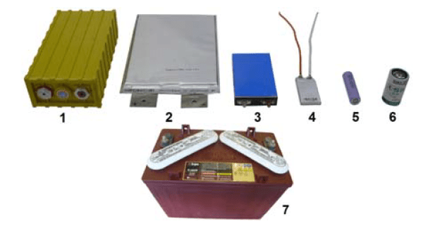
LiFePO4 160Ah and 60Ah (1), LiFePO4 20Ah (2), LiFePO4 8Ah (3), Li-PO 1000mAh (4), Li-Ion 2200 mAh (5), Li-SOCl2 13 Ah (6),
Due to the environmental conditions in which the batteries are normally used and their operation mode (charge – discharge), four tests were performed: chilled battery, heated battery, overcharged battery and short-circuit.
Table 1 contains the basic parameters of the batteries used in electric vehicles.
Table 1. EV traction battery parameters [6,7]
| Type | Energy density [Wh/kg] | No of cycles [SOH 80%] | Charge / Discharge current [C] | Working Temp. [°C] | Nominal Voltage [V] |
|---|---|---|---|---|---|
| Lead-Acid | 35÷50 | 600 | 0,1 / 2 | -20÷40 | 2,1 |
| Ni-Cd | 50÷80 | 500 | 1 / 15 | -20÷50 | 1,2 |
| Ni-MH | 50÷100 | 800 | 1 / 5 | -20÷50 | 1,2 |
| Na-NiCl2 | 90÷110 | 1 500 | 1 / 2 | 245÷350 | 2,6 |
| LiFePO4 | 90÷120 | 3 000 | 5 / 30 | -20÷60 | 3,2 |
| Li-PO | 130÷220 | 500 | 2 / 25 | -20÷60 | 3,7 |
| Li-ION | 160÷200 | 1 000 | 5 / 30 | -20÷50 | 3,6 |
| LTO | 70÷80 | 20 000 | 5 / 20 | -25÷55 | 2,4 |
| Graphene polymer | 1000 | 8000 | 100 / 100 | -20÷60 | 2,3 |
The battery working temperature refers mostly to the operational mode in which the energy is taken from the battery. Most of the batteries including Li-Ion cannot be charged when their temperature is lower than 0°C (32°F). The stated number of cycles coincides with battery State of Health (SOH) reaching the level of 80%. Most battery manufacturers recommend replacing the battery when SOH drops below that value, it does not mean, however, that the battery will cease to work afterwards. Everything depends on conditions in which the particular vehicle were operated. For instance, if a newly manufactured vehicle could achieve a range of 150km on one charge, that vehicle will have a range of 120km at SOH of 80% (≥3000 charge-discharge cycles), 105km at SOH of 70% (≥5000 charge-discharge cycles), 90km at SOH of 60% (≥7000 cycles). Assuming 250 working days per one year, the SOH level of 80% corresponds to 12 years of battery operation, SOH 70% – 20 years, SOH 60% – 28 years, SOH 50% – 36 years. The situation is different in case of Li – Ion batteries, when SOH of 80% is reached after 4 years of operation, SOH 70% – 6 years, SOH 60% – 8 years, SOH 50% – 10 years. During the research, the batteries were tested when exposed to low temperatures and short-circuit conditions. No tests of battery heating and overcharge were performed.
External Cooling
One of the important properties of any electric vehicle battery is its capacity to supply energy in low temperature conditions. Many thermal models of batteries are available [8-18], but the described behavior does not exactly correspond to real battery parameters, especially for temperatures below 0°C (32°F). These parameters are the cause of most electric vehicles poor performance, especially reduction in range, when the ambient temperature drops below 0°C (32°F). This phenomena is caused by internal battery electrochemical reactions performance being highly dependent on the temperature. The drop in effective battery capacity can span, depending on the battery type, from 8 to 25% each time the temperature drops by 10°C (18°F) in relation to reference temperature of 20°C (68°F). When discharged at too low temperature, the battery can be irreversibly damaged by permanent changes in its internal structure, resulting in large drop of SOH value or even a total failure of a battery.
There are measures available, which can prevent these problems from arising, in the form of battery heating systems. Unfortunately, only a small group of manufacturers is installing these conditioning systems in their products, and then, only for vehicles destined for operation in northern parts of Europe and North America. There are several possible methods to employ in the battery conditioning systems, in order to maintain the temperature in the preset operating area. One of the methods is to power individual battery cells with an alternating current at high frequency [19], which increases the internal cell temperature.
The other solution is a liquid conditioning system which, depending on the ambient temperature, can either cool down or heat up the battery. Another way is to harness the air conditioning system of the vehicle in which the battery is installed. This design uses a part of the air conditioning unit to cool or heat the battery (heating is accomplished by a parking heating system e.g. a Webasto) [20].
Finally, there are battery conditioning systems using specially crafted battery boxes, containing heating mats placed at sides and bottom of the box [21]. The heating system is powered either by energy stored in the battery itself, or from mains supply, when the vehicle is connected for the duration of charging and standby. It can be argued, that using extra energy for raising the battery temperature increases the vehicle operation costs, but keeping in mind, that the maintaining higher (proper) battery temperature increases its life, as well as the vehicle range, these steps seem well justified. An exception from this rule, are the vehicles using the molten salt batteries, which to operate, require a high temperature of 245÷350°C (473÷662°F), at power consumption on the average level of 70÷90W, supplied at all times.
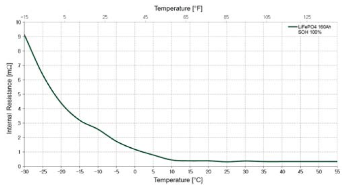

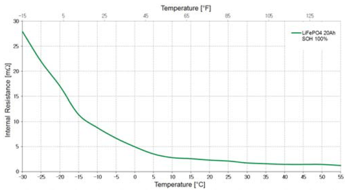


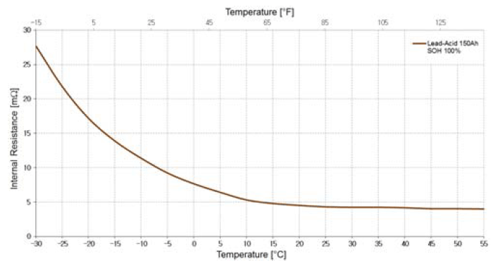
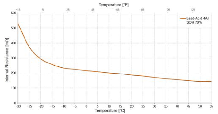
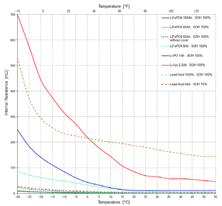
During testing, the batteries under test were placed in the climate chamber, which could hold a preset temperature in the range of -30°C÷55°C (-22°F÷131°F). Preceding the testing, the batteries were held in the climate chamber for a period of at least 8 hours. The measurement of battery internal resistance were conducted by the Electric Vehicle Battery Tester [22]. Measurements were taken from the minimal temperature of -30°C (-22°F), every 5°C (9°F), up to the maximum temperature of °C (131°F). The results of tests for most popular battery types is presented on Fig. 2 ÷ Fig. 9.
A set of internal resistance versus temperature plots for tested batteries is presented in Fig. 10.
External Heating
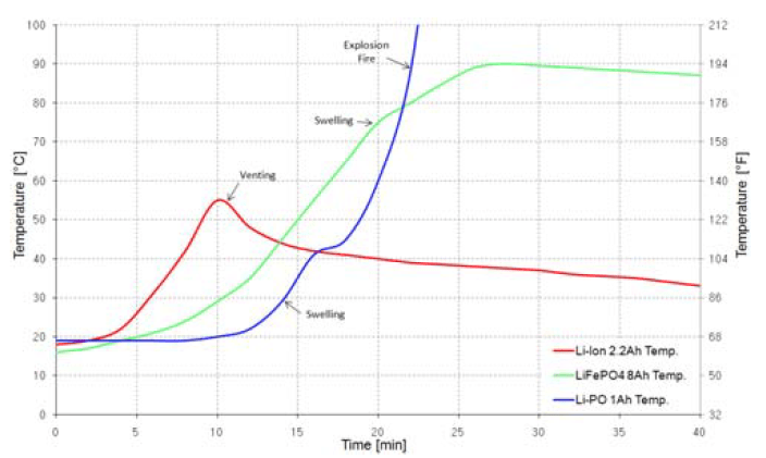
During operation of electric vehicle, it is possible, it will happen in an extremely high ambient temperature (40°÷50°C (104÷122°F)). Taking into consideration additional heat input from internal heating due to high battery circuit current (from e.g. fast charging, high vehicle acceleration), the battery can overheat and become damaged – its internal structure will be destroyed. Another possible mode of failure is thermal runaway, caused by temperature rise on the level of 10°C/minute or higher (Fig.11). It is caused by an exothermic reaction occurring from high temperature which releases large amount of energy in a very short time. The runaway reaction usually results in total loss of the battery, as well as swelling of the battery enclosure from high internal pressure, or even violent rupture of the enclosure associated with expulsion of boiling electrolyte. To prevent the thermal runaway, cooling systems based on liquid or air cooling (using air conditioning system) are applied [20]. During the testing, the batteries were heated at the rate of 10°C(18°F)/15 minutes [23,24].

Overcharge
The process of charging an electric vehicle’s battery is an essential matter considered during engineering an electric powertrain. Engineers working on the powertrain should choose the correct battery type guaranteeing proper vehicle reliability. Choice of the battery type results in requirement of providing the battery with proper operating conditions, such as: limiting the maximal level of shocks and vibration, ensuring water-tightness by designing proper battery enclosure and proper working temperature range by applying a temperature conditioning system. Apart from proper climatic conditions, the battery requires proper charging and discharging parameters, compatible with its requirements (Table 1). It is the purpose of supervisory systems for charging and discharging usually called BMS (Battery Management System), which operate together with onboard and off-vehicle chargers (regular chargers, fast chargers, contactless (induction) chargers, etc.) BMS systems can be constructed as passive or active, active systems have the capacity for controlling (balancing) the voltage levels on individual battery cells. There exists however, a possibility of malfunction of various system components, of e.g. a charger, or a BMS, or a disruption of data exchange between BMS and charger. Another possible risk exists, which can be overlooked by vehicle designers. When the vehicle is operating with fully charged battery, and the regenerative braking is used, it could result in damage to the battery from overcharging, by supplying a large current to an already fully charged battery.
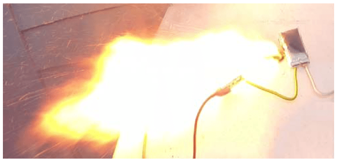
Overcharging a battery reveals in a rise in battery temperature, its swelling due to vaporizing electrolyte or even loss of containment and release of gases to outside atmosphere (Fig. 12.). If the battery is not fitted with adequate safeguards disconnecting circuit (PTC – Positive Temperature Coefficient (temperature over 90°C (194°F)); CID – Current Interrupt Device (internal pressure over 1MPa (145psi)); mechanical safety vent (pressure over 3MPa (450psi))), which would sever the circuit in such case, there is a possibility of battery fire or even explosion [23, 24] (Fig. 13).
Short Circuit
A very serious matter, from the point of safety of vehicle occupants and other traffic users, is the behavior of the vehicle’s battery when subjected to various possible short circuit scenarios: short circuit in the main traction circuit, short circuit from mechanical damage of the battery (puncture, violent shock, crushing, vibration, etc.) and external battery heating. Short circuits or general overcurrent conditions in the main traction current can cause rapid heating of the battery interior which would lead to permanent damage to internal battery structure or to spontaneous battery combustion. In case of battery being heated, after reaching certain temperature there is a possibility of creating a thermal runaway condition which would lead to even quicker temperature rise and create a fire and explosion risk. In everyday life, there are reports of electronic devices (laptop computers, mobile phones, tablets, electric cars, etc.) catching fire due to stressed battery. In many of these cases, the battery itself was not the direct reason of fire, rather the too thin wires connecting the battery to energy consumers tend to overheat, and ignite flames. In order to mitigate the cases when the batteries become fire hazard from overloading or short circuit, various protective devices are being applied in form of protective thermal fuses, which interrupt flow of current when they detect too high temperature.

Another danger of the safety of vehicle and its passengers is the condition of electrical contacts (wire, battery, inverter, motor, fuse and contactor terminals). Loose or corroded terminals can lead to increased resistance, localized heating and even a fire. There are described cases of authorized vehicle service station recommending replacement of whole battery unit, based on computer diagnostic run which reported a failed battery. Meanwhile a simple terminal cleaning job would suffice to return that battery to operational status [25].
A yet different case exists when battery becomes physically damaged as a result of vehicle collision. Then, any thermal fuse fitted outside the battery would become useless, and in case the battery enclosure is designed from poor materials, the battery fire and/or explosion is likely.
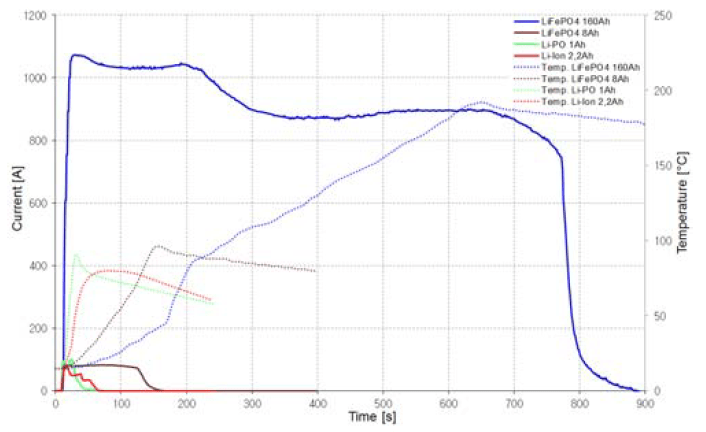
The same type of batteries, as in internal resistance test, were tested. The test was conducted by short circuiting the battery terminals while recording the results of such short circuit. The temperature and current levels were registered, the results are presented on Fig. 14 ÷ Fig. 24.

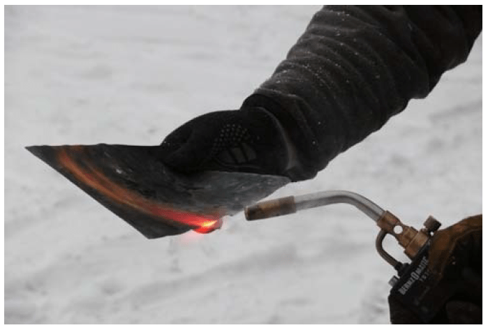
The tested lithium iron phosphate batteries were judged as very safe for operators. During the short circuit test the LiFePO4 160Ah and 8Ah batteries have neither exploded nor ignited, despite reaching high temperature and high current values. The battery with 160Ah capacity has endured the short circuit for 730 seconds with average current value of 942A. A LiFePO4 160Ah battery should supply a current of 3C in 900 seconds, while during the test the recorded value indicated over 6C in almost 800 seconds. After 650 second mark, the battery safety vent activated and released an intense stream of white colored gas cloud from inside the battery (Fig. 14). It has to be stated that vented gasses from a LiFePO4 battery are vary noxious (they are literally boiling and decomposing electrolyte). Apart from normally expected gasses created during combustion of organic materials, such as CO2, CO, H2, CH4, C2H4, C2H6, C3H6, C2H5F1 and others, other toxic compounds like HF (hydrogen fluoride) and POF3 (phosphorous oxyfluoride) are present, derived from fluorine used as lithium battery electrolyte [26].

The short circuit test of 8Ah battery went similar, with one notable difference, when after 20 second mark a rapid rise of case temperature was recorded, after 60 seconds the enclosure began to swell and after 120 seconds the vent opened (Fig. 15). Whole process of short circuit took about 2 minutes with average current of 80A. During the test, the battery achieved the maximal current value of 10.3C (while manufacturer allows 3C max.). The tested LiFePO4 batteries demonstrated very good parameters regarding the safety of operation. The neither exploded, nor ignited and thus did not created a danger for human life and health (Fig. 16). The plates of 160Ah LiFePO4 battery did not ignite even when exposed to open flames (Fig. 17). When operated in proper conditions, this type of battery can be successfully used in electric vehicles for more than 10 years, while retaining their properties (Table 1).
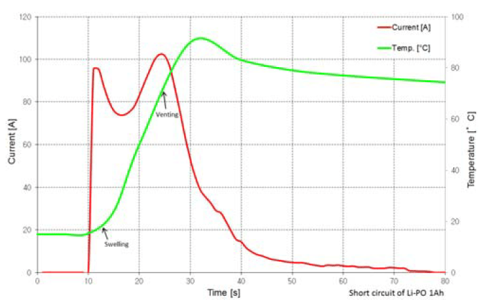
During test run of Li-PO battery, a rise in temperature with an almost simultaneous swelling of battery case (Fig.19) was observed after about 6s from the beginning of terminal short. After about 14s the case seal was broken, releasing vapors into surrounding atmosphere. Any further activity ceased after 30s mark (Fig. 18). It is worth noticing, that the Li-PO battery has shown a capability to supply an enormous current of 102C (with manufacturer stated max. of 25C) with only 1Ah total capacity. The battery did not ignite or explode during this test.

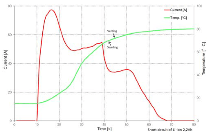

During test run of Li-Ion battery, which is at the moment the most common chemistry employed in electric vehicles, a rise in temperature was noticed after 10 seconds from the onset of short. After 32s mark the case swelling begun, and 4 seconds after that, a safety valve has opened along with a slight emission of gasses and a squirt of electrolyte. The duration of emission was very short (Fig. 20). During the test, the average current achieved was 21C (4.5C max as stated in the datasheet) for about 50 seconds, with nominal battery capacity of 2.2 Ah. The battery did not ignite or explode during this test (Fig. 21).
To compare the operational properties, a primary battery using Li-SOCl2 chemistry and 13Ah capacity was also tested. After 30 seconds from shorting of terminals, the battery temperature began to rise. In the next 3 seconds the case begun to swell, and after 52s from the start of the test, the battery exploded and begun to violently emit fire (Fig. 22, Fig. 23).


Despite igniting and loosing containment, the battery continued to supply current for next 15 seconds. During the test, the batter was able to source current on the order of 3.9C, while the max. allowable discharge current is stated as 0.14C. This test confirmed, that this battery type is unsuitable for electric vehicles, due to real possibility of explosion and fire emission during extreme stress.
Results
The conducted tests have proven, that:
• with dropping temperature, the battery internal resistance rises, which limits the capacity to supply energy. Because of this fact, the application of thermal conditioning systems (heating and cooling) in electric vehicles is recommended, both when the vehicle is moving and when it is stationary. The battery temperature is crucial parameter, it is important that the battery temperature should be 5°C or higher before beginning of the vehicle operation,
• battery overheating can result in exothermic reaction and possibly destroy the battery completely,
• battery overcharge can destroy its internal structure. Assurance of proper BMS operation (balancing and equalization) is of utmost importance,
• short circuit testing resulted in battery venting and release of hot electrolyte. It has to be emphasized, that all tested rechargeable batteries performed adequately, meaning that none of them have ignited nor exploded. It proves that currently produced batteries are high quality. Unfortunately, a lot of data in the Internet contain reports of traction batteries which exploded or ignited,
• state of charge (SOC) of the battery has impact on the amount of heat emitted during the test. The more fully charged a battery was, the more heat it emitted,
• in order to increase safety level for all battery types, a new type of electrolyte could be designed, which during conditions of overheat, overcharge or short circuit would not emit any toxic compounds,
• correctly designed, batteries for electric vehicles should have capacity to withstand: low and high ambient temperature; overheating; short circuit conditions; high pressure inside the casing; excessive charge and discharge currents; low voltage due to greater than nominal depth of discharge (DOD); over voltage resulting from overcharge; shocks and impacts during collisions,
• following the proper operation procedures (maintaining recommended temperature and voltage ranges) should protect the user from nasty surprises while simultaneously provide long and stress free battery life.
REFERENCES
[1] Graphenano and Grabat launch graphene-based batteries, Graphene-info, http://www.graphene-info.com, 08.04.2016.
[2] Noya C., Másdetallestécnicos de las baterías de Graphenano. Certificados TÜV y Dreka., ForoCochesElectricos, http://www.forococheselectricos.com (02.2016)
[3] Lee S.K., Oh S.M., Eunjun Park E., Scrosati B., Hassoun J., Park M.S., Kim Y.J., Kim H., Belharouak I., Sun Y.K., Highly Cyclable Lithium–Sulfur Batteries with a Dual-Type Sulfur Cathode and a Lithiated Si/SiOx Nanosphere Anode, Nano Letters, 15 (5)2015, p. 2863–2868.
[4] Dockrill P., The Netherlands is making moves to ban all nonelectric vehicles by 2025, Science alert, http://www.sciencealert.com, 13.04.2016.
[5] Lambert F., All new cars mandated to be electric in Germany by 2030, electrekt, http://www.electrek.co, 14.06.2016.
[6] Battery University, http://www.batteryuniversity.com, (07.2016).
[7] Battery and Energy Technologies, http://www.mpoweruk.com, (07.2016).
[8] Gu W.B., Wang C.Y., Thermal–Electrochemical Modeling of Battery Systems, Journal of the Electrochemical Society, Volume 147, Issue 8, (2000) p.2910-2922.
[9] Doughty D.H., Butler P.C., Jungst R.G., Roth E.P., Lithium battery thermal models, Journal of Power Sources, Volume 110, Issue 2, (2002) p.357-363.
[10] Biechl H., Rahmoun A., Modelling of Li-ion batteries using equivalent circuit diagrams, Przegląd Elektrotechniczny, 88 (7b/2012), p.152-156.
[11] Malinowski M., Iwan A., Paściak G., Electrical properties of polymer fuel cells based on modified electrolytes, Przegląd Elektrotechniczny, 90 (9/2014), p.73-76.
[12] Liu S., Jiang J., Shi W., Ma Z., Wang L.Y., Guo H., Butler– Volmer-Equation-Based Electrical Model for High-Power Lithium Titanate Batteries Used in Electric Vehicles., IEEE Transactions on Industrial Electronics, Volume 62, Issue 12, (2015) p.7557-7568.
[13] Kasprzyk L., Bednarek K., The Selection of Hybrid Energy Storage for Electrical Vehicle, Przegląd Elektrotechniczny, 91 (12/2015), p.129-132.
[14] Damay N., Forgez Ch., Bichat M.P., Friedrich G., Thermal modeling of large prismatic LiFePO4/graphite battery. Coupled thermal and heat generation models for characterization and simulation, Journal of Power Sources, 283 (2015), p.37-45.
[15] Panchal S., Dincer I., Agelin-Chaab M., Fraser R., Fowler M., Thermal modeling and validation of temperature distributions in a prismatic lithium-ion battery at different discharge rates and varying boundary conditions, Applied Thermal Engineering, 96 (2016), p.190-199.
[16] Li J., Wang L., Lyu Ch., Wang H., Liu X., New method for parameter estimation of an electrochemical-thermal coupling model for LiCoO2 battery, Journal of Power Sources, 307 (2016), p.220-230.
[17] Yan Y., Li Y., Skyllas-Kazacos M., Bao J., Modelling and simulation of thermal behaviour of vanadium redox flow battery, Journal of Power Sources, 322 (2016), p.116-128.
[18] Jiang J., Ruan H., Sun B., Zhang W., Gao W., Wang L.Y., Zhang L., A reduced low-temperature electro-thermal coupled model for lithium-ion batteries, Applied Energy, 177 (2016), p.804-816.
[19] Pesaran A.A., Vlahinos A., Stuart T., Cooling and Preheating of Batteries in Hybrid Electric Vehicles, 6th ASMEASME–JSME Thermal Engineering Conference, Hawaii Island, (03.2003).
[20] Ji Y., Wang Ch.Y., Heating Strategies for Li-Ion Batteries Operated From Subzero Temperatures, Electrochimica Acta, 107 (2013) p.664-674.
[21] Łebkowski A., System for Monitoring of Battery Pack Parameters in an Electric Vehicle Using GSM/GPS Technology, Przegląd Telekomunikacyjny – Wiadomości Telekomunikacyjne, 11 (2014), p.1396-1399.
[22] Łebkowski A., Electric Vehicle Battery Tester, Przegląd Elektrotechniczny, 12 (2016).
[23] Larsson F., Mellander B.E., Abuse by External Heating, Overcharge and Short Circuiting of Commercial Lithium-Ion Battery Cells, Journal of The Electrochemical Society, 161 (2014), p.1611-1617.
[24] Feng X., Weng C., Ouyang M., Sun J., Online internal short circuit detection for a large format lithium ion battery, Applied Energy, 161 (2016), p.168-180.
[25] Toyota Hybrid cheap fix, http://www.imgur.com/gallery/j8Bcp, (08.2015).
[26] Larsson F., Andersson P., Mellander B.E., Lithium-Ion Battery Aspects on Fires in Electrified Vehicles on the Basis of Experimental Abuse Tests, Batteries no. 2: 9, 2016.
Author: dr inż. Andrzej Łebkowski, Akademia Morska w Gdyni, Katedra Automatyki Okrętowej, ul. Morska 83, 81-225 Gdynia, E-mail: andrzejl@am.gdynia.pl.
Source & Publisher Item Identifier: PRZEGLĄD ELEKTROTECHNICZNY, ISSN 0033-2097, R. 93 NR 5/2017. doi:10.15199/48.2017.05.13
