Published by Shoucheng DING1,2, Limei XIAO1,2, Rui HUANG1, Jie LIU1, Shizhou YANG1, Xiao CHAI1,
College of Electrical and Information Engineering, Lanzhou University of Technology (1), Key Laboratory of Gansu Advanced Control for Industrial Processes (2)
Abstract. This paper designed a small terminal of a 35kV substation; it can meet the substation area electricity and the future development of the needs of the vision of growth in electricity demand. The article presents the design of transformers, substation main connection, and lightning protection. The practice shows that it applies to the township (town) of agricultural load and small-scale processing enterprises in electricity.
Streszczenie. W artykule przedstawiono projekt przyłącza podstacji elektroenergetycznej 35kV. W opisie uwzględniono projekt transformatorów, głównego przyłączenia podstacji oraz ochronę odgromową. W praktycznym ujęciu, projekt może mieć zastosowanie w rejonach agroturystycznych i niewielkich zakładach. (Podstacja elektroenergetyczna niskiej mocy na potrzeby małego skupiska odbiorców).
Keywords: miniaturization; transformer; substation main connection; integrated automation.
Słowa kluczowe: miniaturyzacja, transformator, główne przyłącze podstacji, automatyka.
Introduction
In order to meet the electricity needs of the agricultural load and small processing enterprises of the township (town), we designed a 35kV terminal substation. When the substation is put into operation, it can improve the grid structure, reduce the power supply radius, reduce losses and improve the power supply capacity and quality of power supply, and there is a lot of adjustment of the layout of the entire grid. Area altitude 1750, the annual average temperature is 6℃ -9℃, the highest temperature is 35℃, over the years the minimum temperature is -22 ℃ and average annual rainfall is 450mm, the annual average wind speed is 1.6m / s. The instantaneous maximum wind speed and wind: 40m / s dominant wind northwest wind, over the years the maximum depth of frozen soil is 0.8m; underground 16 m depths is no groundwater [1-5].
The main transformer
In order to ensure reliable power supply and maintenance, running facilitate the design of the two main transformers. Taking into account the maximum capacity of a line transmission, the maximum load is 2400kVA. When a main transformer is outage, the remaining capacity of the transformer should be able to meet 70% -80% of the total load. Therefore, a single main transformer capacity shall be: S=2800×70%≈1680kVA. Taking into account the quality of power supply voltage, choose S9-1800/35 three-phase three-winding naturally air-cooled power transformers with OLTC voltage ratio: k =35 ± 8×2.5% / 10kV. Parameters Uk = 6.5%, the main transformer to use low-noise, low loss, oil spills, totally enclosed free hanging core main transformer, installed over-voltage, over temperature, light and heavy gas protection and on-line monitoring device.
Substation transformer
35kV line back to design a transformer connected to the incoming line isolation switch on the outside line, so to ensure the normal power supply are within the power outage, maintenance, emergency lighting, floating power supply. The design capacity is calculated at 0.5% of the main transformer capacity, so it can choose a 30kVA transformer as the transformer model S9-30/35, 35 ± 5% / 0.4, Uk = 6.5%, Y-yn0.
Substation main connection
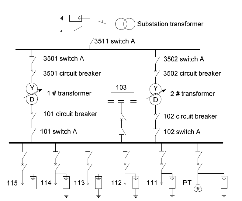
According to the demand for electricity, this system 35kV line is a loop, qualifying four loops 112,113,114,115; its main wiring scheme is shown in Fig. 1. The 35kV voltage circuit into line, substation 35kV into line with isolation switch. The 10kV-side used the single bus connection mode. 35kV into line with isolation switch (GW5-35D), high and low pressure side of the main transformer installed 35kV, 10kV switch, 35kV, 10kV side single busbar connection. 111 interval as a backup interval, the capacitors are mounted on the the the 10kV bus side 103 intervals. The two main transformers are run in parallel
Short-circuit current calculation
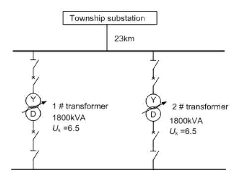
Short-circuit current calculation of the connection is shown in Fig. 2.
Known system power from the new substation 23km select a baseline capacity Sj=100MVA, the reference voltage Uj = Uav. XL=0.4×23×100/372 = 0.6720;
Xc= (0.1+ XL ) /2= (0.1 +0.6720) /2= 0.3860;
UK1=U1- 2/2= 6.5/2 = 3.25;
XT1= (UK1/100) × (Sj / Se) = (3.25/100) × (100/3.6)= 0.9028.
35KV side of the current reference: Ie1=Se / (√3×37) = 1.56 kA. The 10KV lateral current reference: Ie2=Se / (√3×10.5) = 5.5 kA. 35KV side of the maximum operating current: Imax=1.05× (3600 /√3×37) = 59kA. 10KV side of the maximum operating current: Imax =1.05× (20000 / √3 × 10.5) = 208kA. Short-circuit points are shown in Fig. 3. Substation 35kV system, 35kV bus short circuit, short circuit current for 35kV outgoing switch, when the export of short-circuit, the distance from 35kV bus of more recent, can be seen on the bus short circuit, so as to chose d1-point as the selection and validation of 35kV switch, disconnecting switch, current transformer and voltage transformer short-circuit current calculation points.
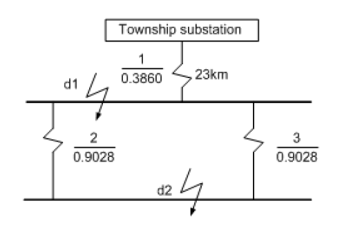
Substation 10kV system, 10kV bus short-circuit, short circuit current for 10kV outgoing switch, when the export of short-circuit, the distance from 10kV bus of more recent, can be seen on the bus short circuit, so as to chose d2- point as the selection and validation of 10KV switch, disconnecting switch, current transformer and voltage transformer short- circuit current calculation points.
The d1-point short-circuits: Impedance: X * =0.3860, I * = 1 / X * = 2.59;
Short-circuit current: Id1 = Ie1×I * = 1.56 × 2.59 = 4.04 kA;
Full Current: ICH = 1.5×Id1 = 1.5×4.04 = 6.06 kA;
Short Circuit Current: ICH = 2.55×Id1 = 2.55×4.04 = 10.30 kA;
Short-circuit capacity: S = √3 Id1Ue = 1.732×4.04 × 37 = 258.9 MVA;
The d2-point short-circuits: Impedance: X * = X1* + X2*/ 2 = 0.3860 +0.9028 / 2 = 0.8374, I * = 1 / X * = 1.194.
Short-circuit current: Id2 = Ie2×I * = 5.5×1.194 = 6.567 kA,
Full Current: ICH = 1.5×Id2 = 1.5×6.567 = 9.851 the KA.
Short Circuit Current: ICH = 2.55×Id2 = 2.55×6.567 = 16.75 kA.
Short-circuit capacity: S = √3 Id2Ue = 1.732×6.567×37= 119.43 MVA.
Main transformer protection
35kV main supply power substation, 35kV side of the three-stage phase current protection as the line of the main protection and back-up protection, protection Selection is PLP66-01 type the microcomputer line direction of the current voltage protection cabinet side. Back-up protection: complex voltage start-up over current protection; overload protection; light gas alarm; over temperature alarm. 10 kV shunt capacitor bank protection: the installation of trip current protection; definite time over current protection; over voltage protection; low-voltage protection; zero sequence over-voltage protection. 35kV, 10kV power distribution unit area and the main transformer area, each has a 600*600 cable trench, outdoor 600*600 summaries of the main ditch backward master control room and carrier machine room.
Substation lightning protection design
The substation suffered lightning damage from two aspects: Ray watch at the substation, lightning lines along the road to the substation invasion. Line lightning, lightning wave intrusion along the road is the main reason for substation mine-stricken, the line insulation level is relatively higher than the insulation level of the substation, the voltage level of incoming and outgoing in substation import and export the installation of zinc oxide surge arresters, which can be used to limit the invasion of the amplitude of the lightning, over-voltage on the device does not exceed the impulse with stand voltage value. The main transformer 35kV side of the commonly used 8.5m door frame, is the protection of a high degree of the hx = 8.5m. The use of a single lightning rod is clearly not meeting the requirements. The use of a lightning rod for two 30m distance of 119m, the axial height of 8.5m equipment to meet the requirements can also be protected.
Integrated substation automation
Scheduling system management principles and the specific circumstances of the 35kV substation remote information and communication using POLLING way, the communication protocol should be coordinated with the county dispatch automation system.
Integrated automation system is a typical distributed architecture, centralized assembly system configuration. Action protected with alarm, the prompt box to display the content. The remote control functions: switch can be remotely operated and print and save records the name of the operator, operating time, the nature of the operation and other information; should have anti-disoperation locking function. Remote functions: remote operation can be carried out on the switch and print and save records the name of the operator, the perk time, the nature of the operation and other information; and should be anti-disoperation. The integrated automation system features include measurement of accumulation, from time to time, at any time print, online maintenance functions, various types of data processing and computing. Substation lighting and maintenance of power by the AC and DC powered control panel. The main control room ceiling and embedded fluorescent lighting, and other room lighting is simple fluorescent lighting. 35kV, 10kV outdoor distribution equipment lighting spotlights lighting set to. Spotlights mounted on independent lightning rod, and the roof of the main control building.
Conclusions
Based hierarchy substation structure is compact, substation automation systems and equipment technology is advanced, and its running is reliable. It can meet the unattended requirements, and covers an area of less practical. It can effectively improve the grid structure, reduce losses, and increase the power supply capacity and quality of power supply, so that it can meet the demand of the area of electricity and the future growth in electricity demand.
REFERENCES
[1] J.Q. Pang. New Developing Trend of Substation Integrated Automation Technology, Automation Application, 4(2010), 49- 50.
[2] Rajakanthan Thurairajah, Meyer Alan S. and Dwolatzky Barry. Computer generated transformer zones as part of township electrification design software, IEEE Transactions on Power Delivery, 15(2000), No. 3, 1067-1072.
[3] Z.J. Liu, H.Y. Chen, K. Chen and M. Ye. The Analysis of Substation Earthing, Friend of Science Amateurs, 11(2012), 36-36.
[4] S.C. Ding, J.H. Li, L.M. Xiao, R. Huang and S.Z. Yang, Intelligent Digital Multi-purpose Vehicle Instrument, Przeglad Elektrotechniczny, 88(2012), nr5b, 64-67.
[5] J.F. Li and C.X. Zhang. A 2D-Role Based Universal Dynamic Configuration Management Infrastructure, Journal of Convergence Information Technology, 7(2012), No. 1, 188-196.
Authors: Shoucheng Ding, associate professor, College of Electrical and Information Engineering, Lanzhou University of Technology, Lanzhou 730050, Gansu, P.R. China, E-mail: dingsc@lut.cn
Source & Publisher Item Identifier: PRZEGLĄD ELEKTROTECHNICZNY, ISSN 0033-2097, R. 89 NR 3b/2013
