Published by Mark KLETSEL1, Nariman KABDUALIYEV2, Bauyrzhan MASHRAPOV2, Alexander NEFTISSOV2,
National Research Tomsk Polytechnic University (1), Pavlodar State University (2)
doi:10.12915/pe.2014.01.21
Abstract. A phase comparison scheme of protection of busbar on the reed switches fixed connections near conductors extending from these busbars which does not require current transformers has been studied. The article provides an analysis of its sensitivity and behavior in different modes
Streszczenie. Porównano metody zabezpieczeń przewodów szynowych przełączników kontaktronowych. Uwzględniono przypadki gdy nie jest stosowany przekładnik prądowy. (Zabezpieczenia szynowych przełączników kontaktronowych)
Keywords: busbar, protection, reed switch, phase comparison, current transformer.
Słowa kluczowe: szyna, zabezpieczenie, kontaktron.
Introduction
It is known that damages on busbars have serious consequences. Most dangerous of them are short circuits through an arc (both – uniphase and interphase), especially in cells of switchgears (distributing devices) [1, 2, 3]. There is rather large number of methods and the devices revealing uniphase short circuits on earth, for example [4]. There is much less sensing protections that reveal two-phase short-circuits. It is possible to include to them logical [5] and differential [6] protections of busbars. And all of them receive information from current transformers which have a number of well-known shortcomings [7, 8]. In this regard works in the direction of creation of the protection which are not using current transformers, for example [9,10] are already conducted. As it was noted at the last international CIGRE conferences [8, 11] because of an incompleteness of these works they are actual and now. Offered protection of busbar (Fig. 1) is one of results of continuation of works in the direction of creation of protection on magnetooperated contacts – reed switches which have explicitly explained in [8, 12, 13, 14] advantages over other magnetooperated elements.
Model of protection
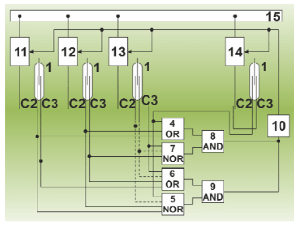
In the flowchart (Fig. 1) Protection 1 – polarized with a reed contact (С) 2 and 3 are installed in a magnetic field of different phase conductors of similar connections are connected to the busbars 15 so that one of the current halfwaves, e.g. positive, closed С 2, and the other- to 3. Contacts 2 are connected to the inputs of the OR gate 4 and the NOR 5 and С 3 – to the inputs of OR element 6 and a NOR 7, the outputs of elements 4 and 7 are connected to AND gate 8, the outputs of elements 5 and 6 – and to 9, the outputs of the elements 8 and 9 – to the executive body of the 10 applicable at the circuit breakers 11-14 connections.
Operation principle
The apparatus operates as follows. In the load mode, and an external short circuit current polarity, at least one of the connections in any half-cycle does not match the polarity of the remaining currents. When the reed switch is closed to 2 this connection, 3 reed switches are closed to other bays, and when the second current half-closed C 3, on the other accessions are closed to 2. As a result, any time the reed switch is closed and the reed switch C 2 C 3 closed. Therefore, the outputs of the elements 5 and 7 and there is no signal as a result, no signals at the outputs of the elements 8 and 9. Executive body of the 10 does not work. If a short circuit on the tire 15 in a single half-closed only to 2 on all connections (connections of all the currents are in phase), the other – to 3. With the closure of C 2 and the lack of contact closure outputs for 3 items 4 and 7, there are signals that the body 10 is triggered. When the closure to the insulation 3 and C 2 signals appear at the outputs of the elements 5 and 6. Thus, whatever the current half cycle is not a short circuit, the device comes into effect at that moment. Due to the high speed, it may qualify for use as a busbar 500 and 750 kV.
Provision of reed switches operation polarity
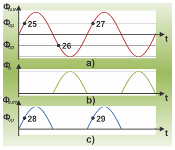
Polarized reed switches in the circuit can be used only if N ≤ 3, where N is the multiplicity of the short-circuit current with respect to the tire, where the reed switch is activated. The fact is that when N > 3 demagnetized permanent magnet, which is an integral part of the reed switch. Therefore, if N > 3 should go on complication – one reed used instead of two with normally open contacts 16 and 17 with two windings 18 and 19, but instead of С 2 and 3 – to 20 and reed switches 16 and 21, 17 respectively. In this case, the winding 18 is a source of EMF, and 19 to compensate for the actions of one of the half-wave voltage. Output windings 19 are connected to the inputs of amplifier 22, amplifier outputs – to the input phase comparison circuit 23 outputs circuits 23 – via a diode 24 to the control winding 19. The polarity switching reed contact [12] is provided as follows. The magnetic flux Φbus (Fig. 3a), created by = alternating current Ibus in bus, for example, phase A connection 12, is the EMF E=-dΦbus/dt output winding 18, which is fed to an amplifier 22. Image EMF must be such that the magnetic flux Φw created by current Iw in the winding 19 is equal to the amplitude of Φbus. EMF in the circuit 23 is shifted in phase by 90 degrees so that the winding 19 Iw coincided in phase with the current Ibus. The polarity of the winding connections 19 to the output circuit 23 should be such that the magnetic flux Φw was directed opposite tensions flow Φbus. Diode 24 passes only one of the half-wave voltage in the winding 19. Consequently, the current in the winding Iw appears only in this half-wave. Figure 3 shows the flow of the Φbus and the Φw and the amount of magnetic flux Φsum acting on the reed switch, and Φop – magnetic flux at which the reed switch is activated. If you do not use the coil 19, the reed switch 16 operates in both half-wave alternating current at Φbus = Φop corresponding to points 25, 26, 27 (Fig. 3a). When a current Iw in the winding 19 on the reed switch 16 acts Φsum = Φbus + Φw that allows it to fire only one half-wave of the alternating current in phase A connection 12.
Sensitivity
For comparison, the currents in the corresponding phases of the connections should be located close to their international conductors so as to eliminate the influence of the currents of neighboring phases. To ensure the safety, distance should not be less than the permissible value. For the closing of the reed switch without replacement within 10 years, it is necessary to their operation occurred at currents exceeding the maximum load currents [11]. Besides Reed them selves have limited sensitivity of m.m.f. response. All this in significantly extent limits the sensitivity of the busbar protection for reed switches [11], and to improve it requires the use of reed switches with a large resource of operation P ≥ 1010 and a small m.m.f.

Application of protection
For application of this protection devices are necessary that allow to mount (fix) the reed such way, that it makes possible to change distance from reed to phase current conductors (busbars) and angle of inclination towards to them (such constructions are known, for example [15, 16]). At the same time to avoid the influence of adjacent (nearby) phases it’s necessary to choose parameters of reeds’ arrangement in accordance with the calculation in [14].
Conclusion
The proposed busbar protection does not require current transformers and has high speed, but its sensitivity is dependent on the lifetime of the reed switch and m.m.f.
REFERENCES
[1] Stanisław Maziarz, Jerzy Szynol, Examining the conditions of eliminating hazard due to arc faults inside switchgears and transformer stations, Przeglad Elektrotechniczny, 2001, nr. 3, pg.62-65.
[2] Roman Partyka, Daniel Kowalak, The effects of fault-arc in medium voltage gas isolated switchboards installed on ships, Przeglad Elektrotechniczny, 2013, nr. 8, 290-293.
[3] Małgorzata Bielówka, Experimental measurements of the fault arc parameters, Przeglad Elektrotechniczny, 2008, nr. 4, 98-101.
[4] Lubomir Marciniak, Application of signal wavelet decomposition for identification of arc earth faults, Przeglad Elektrotechniczny, 2011, nr. 2, 101-104.
[5] G. Bolgartsev, Mark Kletsel, Konstantin Nikitin, V. Matokhin, The device for the centralized current protection of a network, USSR Author Certificate #1644287, 1991, nr. 15.
[6] Kang Y.C., Lim U.J., Kang S.H., Crossley P.A., A busbar differential protection relay suitable for use with measurement type current transformers, Ieee Transactions on Power Delivery, 2005, nr. 20/2, 1291-1298.
[7] Xuesong Zhou, Zhihao Zhou, Youjie Ma, Dongfang Wu, Analysis of Excitation Current in DC-Biased Transformer by Wavelet Transform, Przeglad Elektrotechniczny, 2012, nr 5b, 108-112.
[8] Mark Kletsel, Bases of creation of relay protection on reed switches, Collection of reports of the International scientific and technical conference (Ekaterinburg), 2013,posters sector 10.
[9] Marcin Habrych , Bogdan Miedziński , Hassan Nouri , Witold Dzierżanowski, Performance of ground fault protection using Hall sensor under real conditions of operation, Przeglad Elektrotechniczny, 2010, nr. 7, 181-183.
[10] Krzysztof Ludwinek, Measurement of momentary currents by Hall linear sensor, Przeglad Elektrotechniczny, 2009, nr. 10, 182-187.
[11] L. Kozhovich, M. Bishop, The modern relay protection with current sensors on the basis of the coil Rogovsky. The modern directions of development of systems of relay protection and automatic equipment of power supply systems, Collection of reports of the International scientific and technical conference (Moscow), 2009, 49-59.
[12] Mark Kletsel, The principles of construction and model of differential protection on reed switches, Russian Electrical Engineering, 1991, nr. 10, 47-50.
[13] Mark Kletsel, J. Alishev, A. Manukovsky, Properties of reed switches applied in relay protection, Electrical Technology Russia, 1993, nr. 9, 18-21.
[14] Mark Kletsel, Pavel Maishev, Features of construction on reed switches of differential and phase protection of transformers, Russian Electrical Engineering, 2007, nr. 12, 2-7.
[15] Innovative patent Republic of Kazakhstan No. 19636 Measuring body for relay protection of three-phase symmetric current distributors of 6-35 KV / Mark Kletsel, Assemgul Zhantlesova, Bibigul Zhantlesova : the applicant and the patent holder – the Pavlodar state university named after S.Toraighyrov (KZ). — No. 2006/0882.1; declared 31.07.2006; published 16.06.2008, Bulletin No. 6. — 6 pages
[16] Innovative patent Republic of Kazakhstan No. 20265 Measuring body for relay protection of three-phase symmetric current distributors of 6-10 KV / Mark Kletsel, Assemgul Zhantlesova, Bibigul Zhantlesova, Nurlan Erzhanov : the applicant and the patent holder – the Pavlodar state university named after S.Toraighyrov (KZ). — No. 2006/1351.1; declared 01.12.2006; published 17.11.2008, Bulletin No. 11. — 5 pages
Authors: prof. doctor of technical sciences mr. Mark Kletsel, National Research Tomsk Polytechnic University, Tomsk, Russian Federation, E-mail: Mark2002@mail.ru; mr. Nariman Kabdualiyev, Pavlodar State University, Electroenergetics Faculty, Pavlodar, Lomov str., 64, Republic of Kazakhstan, E-mail: kaznar@mail.ru; mr. Bauyrzhan Mashrapov, Pavlodar State University, Electroenergetics Faculty, Pavlodar, Lomov str., 64, Republic of Kazakhstan, E-mail: bokamashrapov@mail.ru; mr. Alexander Neftissov, Pavlodar State University, Electroenergetics Faculty, Pavlodar, Lomov str., 64, Republic of Kazakhstan, E-mail: shurikneftisov@mail.ru.
Source & Publisher Item Identifier: PRZEGLĄD ELEKTROTECHNICZNY, ISSN 0033-2097, R. 90 NR 1/2014
