Published by Electrotek Concepts, Inc., PQSoft Case Study: Arc Furnace Harmonic Evaluation, Document ID: PQS1004, Date: March 15, 2010.
Abstract: Utility power system harmonic problems can often be solved using a comprehensive approach including site surveys, harmonic measurements, and computer simulations.
This case study presents the results for an arc furnace harmonic evaluation. The case study was completed using the SuperHarm program. The simulation results show harmonic resonances that increase voltage distortion levels when the utility substation capacitor bank was in service.
INTRODUCTION
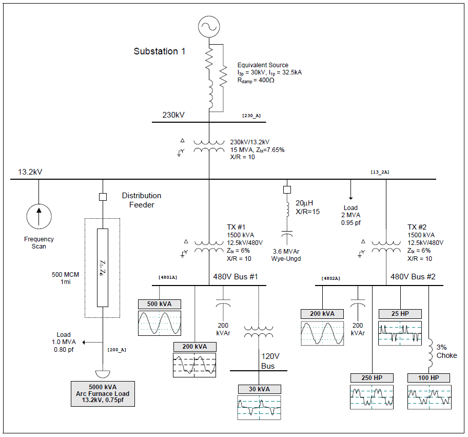
An arc furnace harmonic evaluation study was completed for the system shown in Figure 1. The case study was completed using the SuperHarm program. The accuracy of the simulation model was verified using three-phase and single-line-to-ground fault currents and other steady-state quantities.
The circuit modeled for the case involved a 230kV/13.2kV utility substation supplying two 1,500 kVA customer step-down transformers and one 5,000 kVA arc furnace load. Each customer has a switchable 200 kVAr, 480-volt capacitor bank and a variety of nonlinear loads.
SIMULATION RESULTS
Relevant utility system and customer data for the case included:
Substation capacitor bank rating: 3.6 MVAr
Substation load: 2.0 MVA, 0.95 pf
Feeder load: 1.0 MVA, 0.80 pf
Customer capacitor bank ratings: 200 kVAr
Miscellaneous linear load: 700 kVA
Fluorescent lighting (ITHD = 21.7%): 200 kVA
DC drive (ITHD = 35.3%): 250 hp
PWM ASD (no choke – ITHD = 130.8%): 25 hp
PWM ASD (with 3% choke – ITHD = 45.1%): 100 hp
Switch mode power supplies (ITHD = 77.2%): 30 kVA
Figure 2 shows the simulated current waveform (single phase shown) for the 5,000 kVA, 13.2kV arc furnace operating at a 75% power factor. The current has a fundamental frequency value of 209 amps, an rms value of 224 amps, and a THD value of 35.2%. The simulated arc furnace characteristic represents a measured 18-cycle snapshot of one operating point for the arc furnace. The waveform shown in Figure 2 was created using an inverse DFT with 256 points per cycle.

Figure 3 shows the results for the three frequency scan simulations. Case #1 was the base case with no utility capacitor banks included in the model. Case #2 was the case with the 3.6 MVAr on the 13.2kV substation bus in service. Case #3 was the case with the 3.6 MVAr capacitor bank reconfigured as 2nd harmonic filter. The parallel resonances for Case #2 were about 407 Hz (6.8th) and 660 Hz (11th).
The tuning of the harmonic filter near the 2nd harmonic was required due to the lower frequency components included in the arc furnace current. Arc furnace applications may require less common types of harmonic filters, such as series passive, low-pass broadband, and c-type. A c-type filter may be used for complex loads such as cycloconverters and electric arc furnaces.
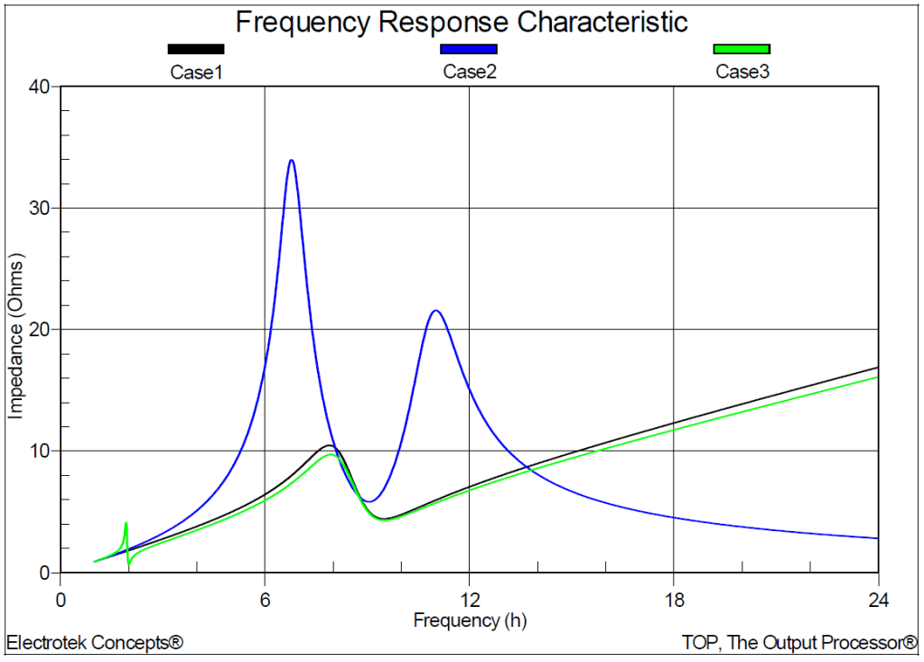
Table 1 summarizes the results for the three distortion simulations. The table includes the simulated voltage distortion (THD) at the five buses for the three different operating conditions. A number of locations exceed the voltage limitation of 5% THD. Adding the 13.2kV, 3.6 MVAr substation capacitor bank in Case 2 caused the two customer 480-volt buses to exceed 5% THD. Reconfiguring the capacitor bank as a 2nd harmonic filter in Case 3 reduced the voltage distortion on the customer buses to below 5% THD.
Table 1 – Summary of the Simulated Voltage Distortion Results
| Case Number | 13.2kV Bus | 13.2kV Feeder | 480V Bus #1 | 480V Bus #2 | 120V Bus #1 |
|---|---|---|---|---|---|
| 1 | 2.288% | 5.902% | 2.478% | 4.828% | 3.808% |
| 2 | 3.439% | 6.478% | 5.780% | 7.151% | 5.286% |
| 3 | 2.191% | 5.790% | 2.353% | 4.713% | 3.766% |
Figure 4 shows the simulated 3.6 MVAr capacitor bank current for the Case 2 operating condition. The current has a fundamental frequency value of 130 amps, an rms value of 132 amps, and a THD value of 18.5%.

SUMMARY
This case study summarizes the results for an arc furnace harmonic evaluation. The simulation results show harmonic resonances that increase voltage distortion levels when the utility substation capacitor bank was in service. The initial solution might seem to be to install a 5th harmonic filter; however, filters should be tuned below the lowest significant harmonic being generated. In this case, that was the 2nd harmonic.
REFERENCES
- Power System Harmonics, IEEE Tutorial Course, 84 EH0221-2-PWR, 1984.
- IEEE Recommended Practice for Monitoring Electric Power Quality,” IEEE Std. 1159-1995, IEEE, October 1995, ISBN: 1-55937-549-3.
- IEEE Recommended Practices and Requirements for Harmonic Control in Electrical Power Systems, IEEE Std. 519-1992, IEEE, ISBN: 1-5593-7239-7.
RELATED STANDARDS
IEEE Std. 519-1992
IEEE Std. 1159-1995
GLOSSARY AND ACRONYMS
ASD: Adjustable-Speed Drive
CF: Crest Factor
DFT: Discreet Fourier Transform
DPF: Displacement Power Factor
PCC: Point of Common Coupling
PF: Power Factor
PWM: Pulse Width Modulation
TDD: Total Demand Distortion
THD: Total Harmonic Distortion
TPF: True Power Factor
