Published by Electrotek Concepts, Inc., PQSoft Case Study: Temporary Overvoltage and Grounding Transformer Analysis, Document ID: PQS1203, Date: January 25, 2012.
Abstract: This case study presents the results for a wind plant temporary overvoltage (TOV) and grounding transformer transient analysis. The case study investigated the potential for excessive temporary overvoltages during single-phase faults on a 34.5 kV wind plant collector circuit. The results show that the application of properly rated grounding transformers can reduce the resulting temporary overvoltage levels on the collector circuit below the surge arresters capability.
INTRODUCTION
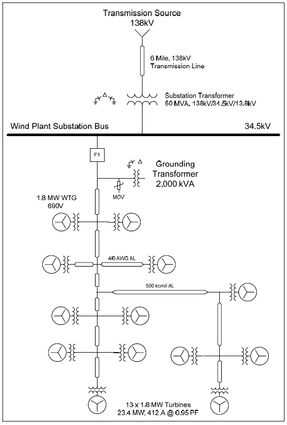
A wind plant temporary overvoltage (TOV) and grounding transformer transient analysis case study was completed for the system shown in Figure 1. The case study investigated the potential for excessive temporary overvoltages during single-phase faults on a collector circuit. The power conditioning mitigation alternative of grounding transformers was also evaluated. The simulations were completed using the PSCAD® transient program. A transient model was created to simulate a wind plant collector circuit and the resulting temporary overvoltages during single-phase faults.
SIMULATION ANALYSIS
The simulation model included a 138 kV wind plant substation and a 6-mile transmission line supplying a 50 MVA, 138/34.5/13.8 kV substation transformer. One 34.5 kV collector circuit with thirteen 1.8 MW Type 4 full conversion wind turbine generators was included in the model. This resulted in a wind production of 23.4 MW (412 A @ 0.95 power factor) for the collector circuit. The model was designed so resulting temporary and transient overvoltages on the collector circuit during fault conditions could be determined. The accuracy of the simulation model at 60 Hz was determined using simulated fault current magnitudes and other steady-state quantities, such as cable line charging (MVAr) and feeder load flow values (MW & MVAr). The representation of the system short-circuit equivalent at the 138 kV source substation, under assumed normal system conditions, included:
Three-phase (I3φ) fault current: 17,500 A @ -85.0° (4183 MVA)
Single-line-to-ground (IφG) fault current: 20,000 A @ -85.0° (4780 MVA)
These values were converted to ohms for the PSCAD representation, which included a three-phase voltage source with positive and zero sequence impedances. The 6.0 mile, 138 kV transmission line was modeled using the following data:
Length: 6.0 mi
Positive sequence impedance (Z1): 0.11660 +j0.68140 Ω/mi
Zero sequence impedance (Z0): 0.40245 +j2.72030 Ω/mi
Positive sequence line charging (XC1): 0.168142 MΩ-mi
Zero sequence line charging (XC0): 0.296228 MΩ-mi
The coupled π-section model in PSCAD was used to model the transmission line. That assured accurate representation of both the series impedances, as well as the line charging characteristics of the transmission line.
The substation transformer was modeled in PSCAD using the classical three-phase, three winding transformer model. The nameplate impedance data for the substation transformer included:
| %Z1 @ 50 MVA, 138/34.5/13.8 kV | % R | % X |
|---|---|---|
| Primary – Secondary (H-X) | 0.320 | 8.50 |
| Primary – Tertiary (H-Y) | 0.400 | 10.00 |
| Secondary – Tertiary (X-Y) | 0.020 | 4.00 |
| %Z0 @ 50 MVA, 138/34.5/13.8 kV | % R | % X |
|---|---|---|
| Primary – Secondary (H-X) | 0.320 | 8.00 |
| Primary – Tertiary (H-Y) | 0.400 | 9.00 |
| Secondary – Tertiary (X-Y) | 0.020 | 3.50 |
The 34.5 kV collector circuit cable sections were included in the transient model using the following impedance data:
Conductor: 500 kcmil AL
Length: 2,000 feet
Positive sequence impedance (Z1): 0.0499 +j0.0553 Ω/1000’
Zero sequence impedance (Z0): 0.1508 +j0.0599 Ω/1000’
Line charging (B/2): 11.5 μmhos/1000’
It was assumed that positive and zero sequence line charging values were the same. The coupled π-section model was used to model each cable section. That assured accurate representation of both the series impedances, as well as the line charging of the collector system cables.
The wind turbine generators were doubly-fed induction machines, which for the purposes of this case study, were modeled using a three-phase voltage source with 0.20 per-unit subtransient impedance with an X/R ratio of 25. This assumption resulted in a fault current to rated current ratio (IF/IFL) of 5.0 per-unit. The turbine generator data included:
Active Power Rating: 1.8 MW
Power Factor: 0.95 per-unit
Rated Voltage: 690 V
Subtransient Reactance (X”): 0.2 per-unit
X/R Ratio: 25
The PSCAD representation included the respective three-phase voltage source (e.g., 690 V) and positive sequence impedance. The phase angle of the voltage source was adjusted to achieve the desired load flow for each turbine (1.8 MW) and collector circuit (e.g., ~23.4 MW). The turbine transformers were modeled using the three-phase, two-winding transformer model. The turbine pad-mounted step-up transformer data included:
Three Phase Rating: 1,900 kVA
Secondary Voltage: 690 V (grounded-wye)
Primary Voltage: 34.5 kV (grounded-wye)
Nameplate Impedance: 9.0% (X/R Ratio = 12)
The collector circuit grounding transformer was modeled using the three-phase, two winding transformer model. The transformer data included:
Three Phase Rating: 1,500 – 2,000 kVA
Secondary Voltage: 480 V (delta)
Primary Voltage: 34.5 kV (grounded-wye)
Nameplate Impedance: 5.75% (X/R Ratio = 7.5)
The equivalent voltage source magnitude at the 138 kV substation source bus was increased somewhat so the resulting 34.5 kV bus voltage would be approximately 1.0 per unit for the basecase operating condition of having all 13 turbines in service.
Case 1 included the collector circuit and all 13 wind turbine generators. The phase angle for the equivalent turbine models was adjusted to achieve the desired load flow for each turbine (~1.8 MW) and collector circuit (e.g., ~23.4 MW). Case 1 did not include any surge arresters, faults, or circuit breaker operations. It was completed to assure that the desired steady-state voltages and power flow quantities were achieved before the fault cases were completed.
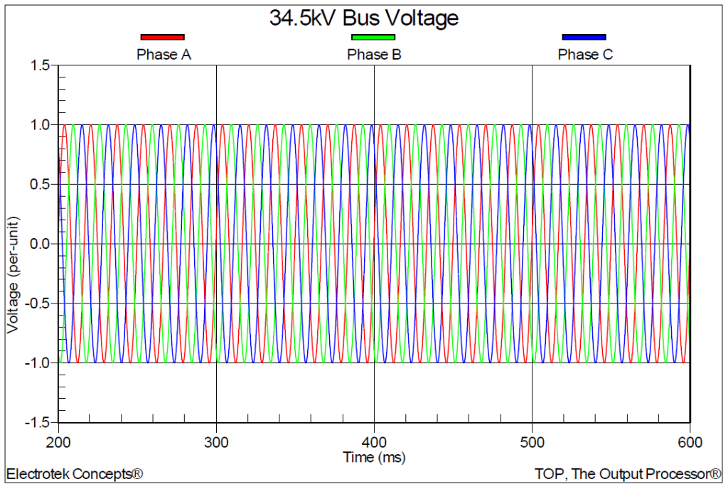
The steady-state 34.5 kV bus voltage (in per-unit) is shown in Figure 2. The simulation results for Case 1 included:
138 kV RMS Primary Bus Voltage: 139.4 kV (1.01 per-unit)
34.5 kV RMS Secondary Bus Voltage: 34.6 kV (1.00 per-unit)
Transformer Secondary RMS Current: 399.4 A (564.8 amps peak)
Transformer Secondary Active Power: 23.4 MW
Transformer Secondary Reactive Power: -4.8 MVAr
Transformer Secondary Apparent Power: 23.9 MVA
Transformer Secondary Power Factor: 0.98
Collector Circuit #1 Active Power: 23.4 MW
Case 2 included a single-line-to-ground fault on the collector circuit with 13 wind turbines in service. The case included the following sequence of events:
1) 0.00 Seconds – Begin case with all circuit breakers closed (no MOVs or grounding transformers)
2) 0.20 Seconds – Initiate single-phase-to-ground (Phase A) fault on collector circuit near bus
3) 0.30 Seconds – Open 34.5 kV collector circuit breaker (6 cycles – fault remains on circuit)
4) 0.60 Seconds – End case
The case basically simulates the isolation of the collector circuit by opening the circuit breaker with a single-phase fault still on the ungrounded collector circuit. This produces six cycles of fault current from the 138 kV source and 13×1.8 MW turbines supplying the fault after the circuit breaker opens. The corresponding three-phase rms (I3φ) fault current for Case 2 was 1,399 amps with 13 turbines.
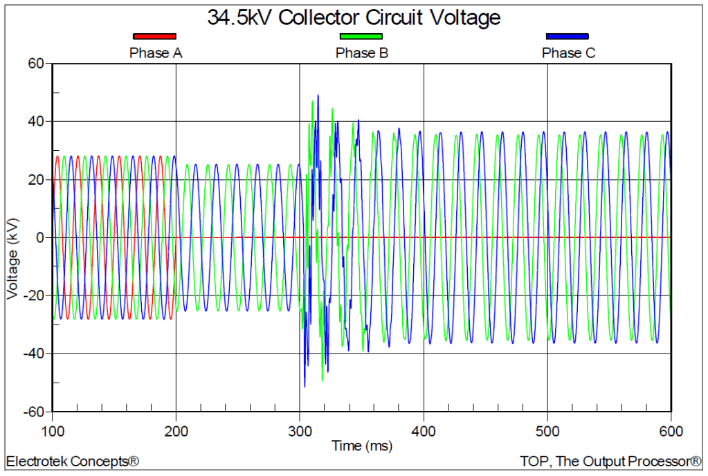
The 34.5 kV collector circuit voltages for Case 2 are shown in Figure 3. The waveform shows the effect of the single-phase-to-ground (Phase A) fault at 0.2 seconds and the circuit breaker opening at 0.3 seconds. After the initial oscillatory transients have dissipated, the peak fundamental frequency temporary overvoltage on the healthy phase (Phase C) is 49.518 kV, which is 1.76 per-unit (49.518 / (34.5*sqrt(2)/sqrt(3)). This value is somewhat higher than the theoretical value of 1.73 per-unit, which is primarily due to the capacitance of the collector circuit.
The single-line-to-ground fault current supplied from the turbines is approximately 23 amps, with no additional grounding source on the system after the collector circuit breaker opens. This means that the ratio of single-line-to-ground current to three-phase current (IφG/I3φ) is approximately 0.02 for Case 2, which means that the system is not effectively grounded. Effectively grounded systems require an IφG/I3φ ratio greater than 60%.

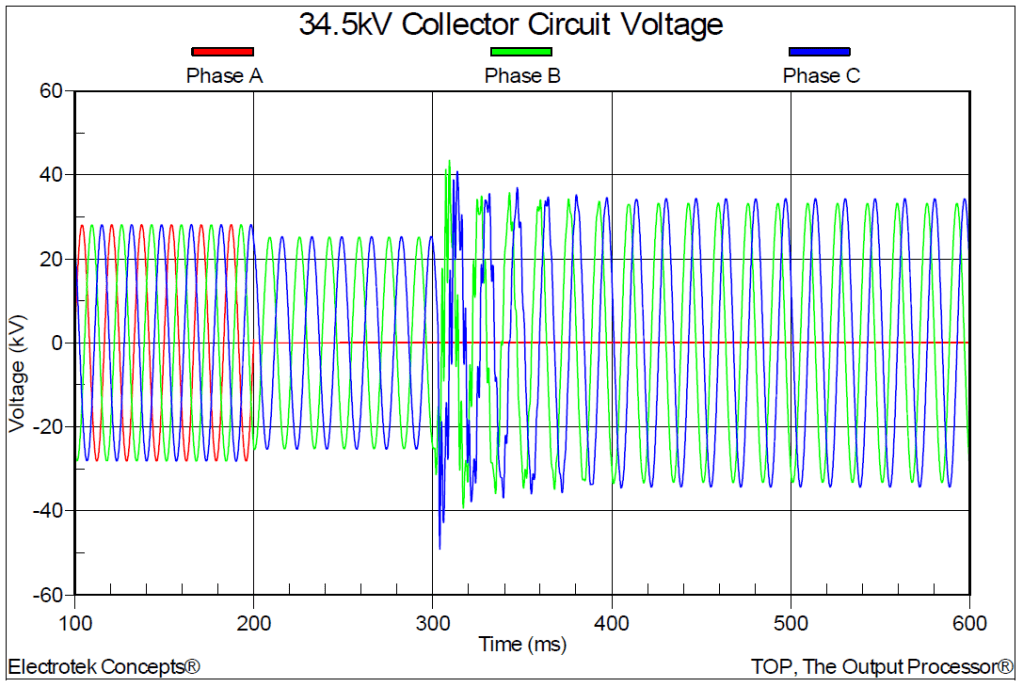
Case 3 included a 1,500 kVA grounding transformer connected to the collector circuit. The 34.5 kV collector circuit voltages for Case 3 are shown in Figure 4. The peak temporary overvoltage on the healthy phase was 36.525 kV (1.30 per-unit) for Case 3. That compares with a value of 1.76 per-unit for Case 2.
The simulated single-line-to-ground fault current supplied from the turbines for Case 3 was 798 amps with the 1,500 kVA grounding transformer in-service after the collector circuit breaker opens. This means that the ratio of single-line-to-ground current to three phase current (IφG/I3φ) is approximately 0.57 (798 / 1399). A ratio of 0.6 is required for a system to be considered to be effectively grounded.
Case 4 included a 2,000 kVA grounding transformer connected to the collector circuit near the substation bus. The 34.5 kV collector circuit voltages for Case 4 are shown in Figure 5. The peak temporary overvoltage on the healthy phase was 34.435 kV (1.22 per-unit) for Case 4.
The simulated single-line-to-ground fault current supplied from the turbines for Case 3 was 946 amps with the 2,000 kVA grounding transformer in-service after the collector circuit breaker opens. This means that the ratio of single-line-to-ground current to three phase current (IφG/I3φ) is approximately 0.68 (946 / 1399). A ratio of 0.6 is required for a system to be considered to be effectively grounded.
The simulation results summarizing the effectiveness of the various grounding transformer ratings for the collector circuit are shown in Table 1. The simulation results show that the temporary overvoltages are greater than 1.73 per-unit without any grounding transformers and that a 2,000 kVA grounding transformer is required to achieve an effectively grounded system.
Table 1 – Temporary Overvoltage Results and Grounding Transformer Ratings
| Case Number | Fault Location and Type | TOV Vpk (kV) (per-unit) | Gnd Tx Rating (kVA) | IφG/I3φ Ratio |
|---|---|---|---|---|
| 2 | 1φ @ Circuit #1 | 49.518 (1.76) | 0 | 0.02 |
| 3 | 1φ @ Circuit #1 | 36.525 (1.30) | 1,500 | 0.57 |
| 4 | 1φ @ Circuit #1 | 34.435 (1.22) | 2,000 | 0.68 |
The simulation results showed that even with a grounded-wye/grounded-wye turbine transformer connection, excessive temporary overvoltages were still present during the single-phase faults on the isolated collector circuit. This is due to the fact that the turbine generators are ungrounded and therefore do not provide zero sequence fault currents. There is a common misconception that the grounded-wye/grounded-wye turbine transformer connection provides a ground source for collector circuits that become isolated from the substation bus.
SUMMARY
This case study presented a wind plant temporary overvoltage and grounding transformer transient analysis case study. The case study investigated the potential for excessive temporary overvoltages during single-phase faults on a 34.5 kV wind plant collector circuit. The results show that the application of properly rated grounding transformers can reduce the resulting temporary overvoltage levels on the collector circuit below the surge arresters capability.
Mitigation of temporary overvoltages in wind plants allows surge arresters to be applied that provide adequate surge protection margins for equipment while reducing the risk of arrester failure. Surge arresters are applied to a power system based on the line-to-ground voltages under normal and abnormal operating conditions. During ground-fault conditions, the line-to-ground voltages can increase to 1.73 per-unit or higher on isolated collector circuits. Therefore, the successful application of surge arresters is quite dependent on the effectiveness of the system grounding.
The application of grounding transformers will reduce the zero sequence impedance of the system and the resulting temporary overvoltages. In other words, an effectively grounded system allows the use of lower rated surge arresters that provide better transient surge protection. In general, effectively grounded systems limit the resulting temporary overvoltages to less than 1.25 per-unit.
An MOV surge arrester should not be considered as a means for reducing temporary overvoltages, but rather the arrester must be able to survive the temporary overvoltage level during the single-phase fault on the isolated collector system. The temporary overvoltage capability that is provided by the arrester manufacturer defines the magnitude and duration of the sinusoidal fundamental frequency voltage that can be applied to the arrester without causing failure.
REFERENCES
- IEEE Recommended Practice for Grounding of Industrial and Commercial Power Systems, IEEE
Std. 142 (IEEE Green Book), IEEE, November 2007, ISBN: 0738156392. - IEEE Recommended Practice for Monitoring Electric Power Quality,” IEEE Std. 1159-1995, IEEE,
October 1995, ISBN: 1-55937-549-3. - IEEE Recommended Practices and Requirements for Harmonic Control in Electrical Power
Systems, IEEE Std. 519-1992, IEEE, ISBN: 1-5593-7239-7.
RELATED STANDARDS
IEEE Std. 142
GLOSSARY AND ACRONYMS
DFT Discreet Fourier Transform
PCC Point of Common Coupling
TDD Total Demand Distortion
TOV Temporary Overvoltage
