Published by Jarosław WIATER, Politechnika Białostocka, Wydział Elektryczny, Katedra Telekomunikacji i Aparatury Elektronicznej
Abstract. This paper presents a ground potential rise (GPR) and voltage difference measurement results. Measurements were made for a model of a pole installed in homogeneous ground. The test stand was built in high voltage lab. It allows safe high voltage testing of different types of ground systems. During measurements current and voltage surges were produced by the UCS 500M impulse generator. The prepared physical model makes it possible in the future to investigate different methods of reducing the value of touch and step voltages in the vicinity of earth systems.
Streszczenie. W artykule przestawiono wyniki pomiarów wzrostu potencjału ziemi i różnicy napięć dla modelu słupa zainstalowanego w jednorodnej ziemi. Specjalnie zbudowane stanowisko badawcze umieszczono w laboratorium wysokich napięć. Konstrukcja i lokalizacji umożliwiła prowadzenie badań różnych typów systemów uziomowych w sposób bezpieczny z wykorzystaniem generatorów prądów udarowych wysokiego napięcia. Podczas badań udary prądowo-napięciowej wytwarzał generator udarowy UCS 500M. Zbudowane stanowisko badawcze umożliwi w przyszłości badanie różnych metod ograniczania poziomów napięć krokowych i dotykowych w pobliżu elementów systemu uziomowego. Wyniki pomiarów wzrostu potencjału ziemi i różnicy napięć dla modelu słupa zainstalowanego w jednorodnej ziemi
Słowa kluczowe: wyładowanie piorunowe, napięcie krokowe, wzrost potencjału ziemi, wysokonapięciowe badania.
Keywords: lightning, step voltage, Ground Potential Rise (GPR), high voltage tests.
Introduction
The basic requirements and features of an earthing system can be summarized as follows:
• Provides personnel safety and reduces fire hazard during fault conditions by maintaining low or zero potential difference between all conductive elements of a structure.
• Provides low impedance path for lightning current to earth and improves system tolerance to electrostatic energy discharge;
• Minimizes service interruptions and equipment damage under fault conditions;
• Facilitates equipment operation i.e. signaling with earth return by ensuring low impedance ground reference;
• Reduces radiated and conducted electromagnetic emissions and susceptibility of equipment.
Personnel safety in various objects under power fault conditions has been studied extensively [1] and is well defined in international standards [2]. A lot of technical publications related to transient lightning behavior of various ground grids are also available [3, 4, 5, 6]. However, they usually consider only an overall scalar potential distribution or Ground Potential Rise (GPR). Still not much information concerning the actual values of step and touch voltages that people can be exposed to during lightning strokes is provided [7]. Moreover, the analyses often relate to a single frequency (usually a low frequency), which does not give complete in-formation because of strong dependence of the behavior of ground grids on frequency. Furthermore, aboveground structures are also often neglected. These structures however, are very important be-cause on the one hand, a current distribution in aboveground structure is determined by the location and specific behavior of earth electrodes and on the other hand, a current distribution in buried electrodes depends on the geometry of the aerial part of the structure.
The main purpose of the article is to present the results of potential measurements in the closest vicinity of the pole to the earth system. Conducting measurements using high voltage generators is very risky in real conditions. Hence, the physical model of the pole in homogeneous soil was built in the laboratory. Such a test stand will allow for safe conduct of measurements using high-voltage surge generators.
Ground Potential Rise, Step And Touch Voltages
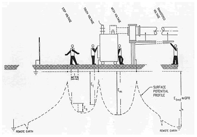
Dissipation of the lightning current into the earth means that a good electrical connection to earth at zero potential reference i.e. remote ground should be provided. The impedance of this connection is not ideal due to the soil resistivity within which the grounding system is buried. Hence, the lightning current that flows through the earthing network to earth results in the local ground potential rise (GPR) with respect to remote ground. The GPR is a source of potential gradients within and around the earthing network area, which determine the values of step and touch voltages. An illustration of GPR, step and touch voltages is presented in figure 1.
The step voltage is defined as the potential difference between one’s outstretched feet, usually 1 m apart. The touch voltage is the potential difference between one’s outstretched hand touching an earthed structure and one’s feet. The maximum hand-reached distance of 1 m is usually assumed.
The figure presents also some special cases of touch voltages. The worst case of the touch voltage called a mesh voltage is defined as a potential difference between the centre of a given mesh and an earthed structure. The potential transferred for some distance via reference metallic conductor produces the transferred voltage.
Research Stand And Measurement Results
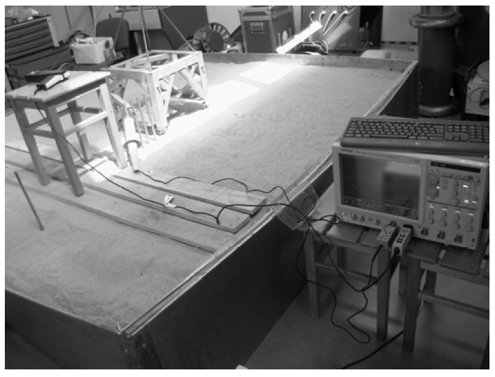
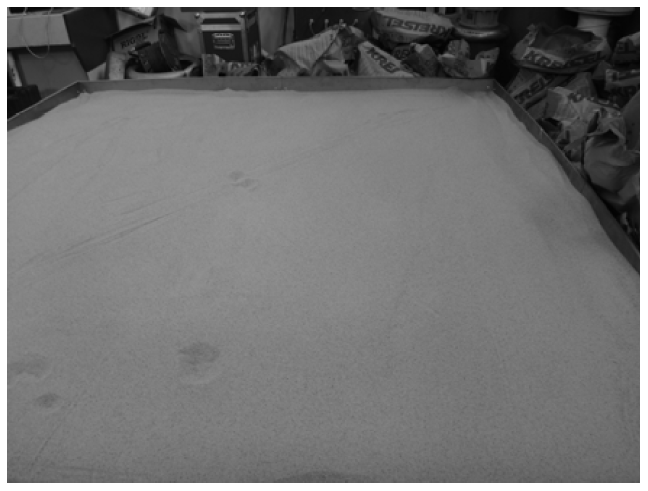
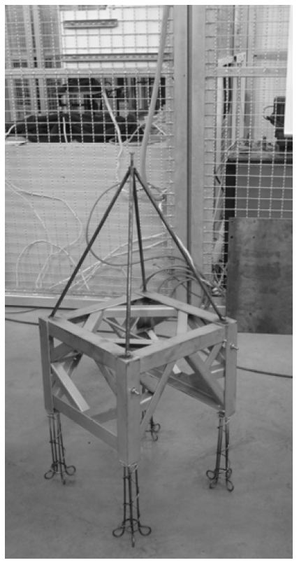
Determining the level of shocks is essential for the safety of people near structures that can be struck by lightning. In order to be able to carry out safe measurements in the conditions closest to reality, a metal bathtub of 2.5 m wide, 2.5 m long and 0.5 m high was built (fig. 2). The metal bath was filled with a quartz decorative sand with a resistivity of 1500 Ωm (fig. 3). The sand was sifted and the grains were no larger than 1 mm. The voltage-current surge was brought to the top of the column structure. The column itself is made of metal truss 40x40x30 cm (width, depth, height). To the corners of the metal truss, a metal structure imitating the base earth was connected (fig. 4). The built-in structure is symmetrical.
Voltage-current surges were produced by the high-voltage impulse generator – UCS 500M6B. The UCS 500M6B cover transient and power fail requirement according to international standards with voltage capability of up to 6,6kV.
• voltage (open circuit) 250-6600V,
• pulse front time 1,2μs +/- 30%,
• pulse time to half value 50μs +/- 20%,
• current (short circuit) 125-3300A,
• direct output Via HV-coaxial connector, Zi=2Ω.
To measure output current of the generator TCP0150 Tektronix AC/DC current probe was used (DC to 20 MHz bandwidth, 500 A peak pulse current). Voltage and current waveforms were registered by Tektronix DPO 7254 digital oscilloscope.
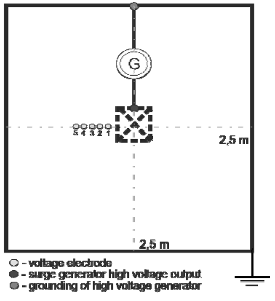
Arrangements during step voltage measurements presents figure 4 and 5. The generator output terminal was connected to the column support structure. The generator ground terminal was connected to a metal tub. Additional electrodes for measuring the voltage distribution near the pole are pushed every 5 cm. The column is centrally located in a metal tub.
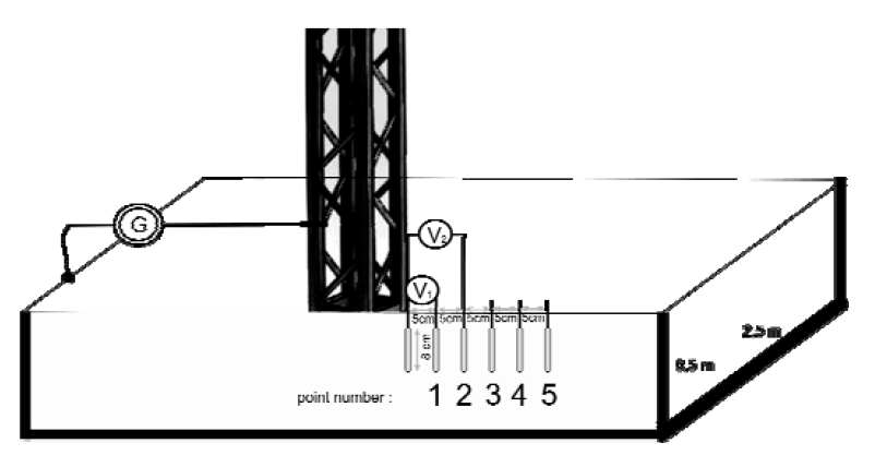
The depth of foundation of the additional voltage electrodes was set at 8 cm. For the purpose of analysis, the human foot is usually represented as a conducting metallic disc and the contact resistance of shoes, socks, etc., is neglected [4]. Traditionally, the metallic disc representing the foot is taken as a circular plate with a radius of 0,08 m. A value of 1000Ω were used as a resistance of a human body from one foot to the other foot [10]. During the measurements voltage electrodes dug on 0,08 m depth represents human foot.
Measurement results are shown in figures 7-10. Figure 7 shows generator output current for different capacitor charging voltages. Figure 8 and 9 shows the step and touch voltage waveforms depending on the capacitor charging voltage for point 1. The step voltage changes according to the distance from the pole are shown in figure 10. The results of the measurements are summarized in table 1 and 2.
Table 1. Step and touch voltage results
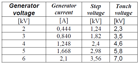
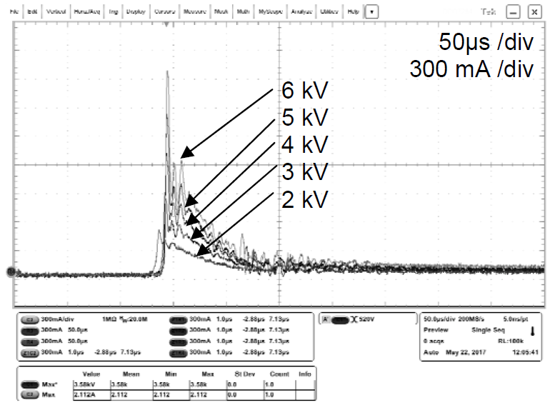
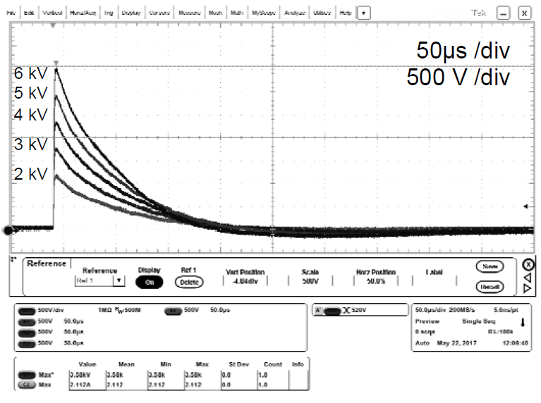
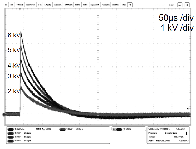
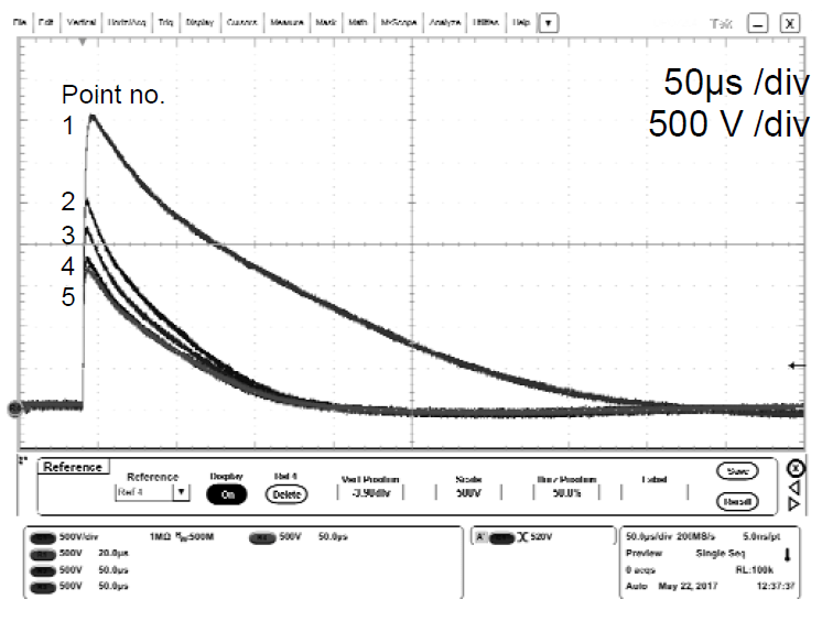
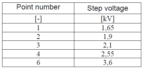
Table 2. Step voltage results depending on the distance
Discussion
The measurements performed show a linear relationship between the generator’s charge voltage and the value of the step and touch voltages. Debatable issue from the point of view of the threat of living beings is the value of the spacing between the legs when measuring step and touch voltage. From the anatomical point of view, the distance of 1 meter between the legs is only possible during a quick walk. It is difficult to imagine a situation when someone is going quickly and simultaneously touching an element that may potentially be energized during an earth lightning strike. The author’s experience and press reports clearly indicate that an electric shock caused by a lightning strike occurs when the victim is standing under an object such as a tree. According to the author, in case of electric shock caused by lightning discharge, a new stand voltage definition should be introduced. Stand voltage it is potential difference on the ground surface at anatomical distance between the legs equal 5 cm.
Conclusions
Generally lightning strikes have got a sudden and unexpected nature. In present time when mass-media delivers information about electric shock caused by lightning strike without any delay de-tail knowledge about lighting safety is necessary. This also creates life fear in society. Unfortunately very often happens that those information’s are not true, not complete and not compliant with science knowledge. Medical aspects of news are simple. Victim survived or not. Unreliable information’s causes periodically and rapid increase attraction about lightning electric shock hazard. Most of questions concentrates on one subject. How to correctly behave during thunderstorm. This problem is not so easy as it seems to be. In our climate conditions there are up to several current strokes during cloud-to-earth lightning discharge [1,2,3]. It is difficult to estimate the actual number of consecutive components of lightning discharge. It is, however, possible to establish in safe way possible values of step, touch, stand voltages during lightning surge current excitation.
Electrical accidents caused by electric shocks occur during work, leisure and day-to-day operations. They always involve certain economic, human and social losses as well as the appearance of fear.
In order to reduce losses, it is necessary to use appropriate technical solutions supported by appropriate normative acts, which will reduce the number of catastrophic events and, in most cases, limit their effects.
Preventive measures should be based on the development and implementation of such technical solutions, which, in extreme situations, protect people from the effects of lightning strikes, irrespective of where they are located. One cannot forget about indirect prevention, which should include, first of all, various information measures promoting the use of lightning-resistant technical solutions. The carelessness and misbehavior of man largely leads to accidental injuries, so it is appropriate to educate young people from an early age. Another important but also important aspect is the minimization of the effects of electric shocks by spreading the rules of first aid at the scene of an accident. There is also a clear progress in the lightning protection of building constructions, resulting in changes in the approach to many safety issues during lightning discharges. It is therefore important to consider the introduction of legal regulations recommending participation in periodic lightning protection training for designers and lightning protection workers on new buildings: both public utilities, residential homes and industrial facilities.
The presented results of the measurements clearly indicate a high level of danger of step voltages caused by lightning discharges. The number of traumas causing injuries in people is growing, so it is important to continue research in this area.
Acknowledgment: The research was conducted within the project S/WE/1/2015, financially supported by Polish Ministry of Science and Higher Education.
REFERENCES
[1] J. B. M. van Waes, A. P. J. van Deuersen, M. J. M. van Riet, F. Provoost; Safety Aspects of GSM Systems on High-Voltage Towers: An Experimental Analysis; IEEE Transactions on Power Delivery, vol. 17, no. 2, April 2002; pp. 550–554.
[2] IEEE Std 80-2000: IEEE Guide for Safety in AC Substation Grounding.
[3] Grcev L. D.; Computer Analysis of Transient Voltages in Large Grounding Systems; IEEE Transactions on Power Delivery, vol. 11, no. 2, pp. 815–823, April 1996.
[4] Geri A.; Practical Design Criteria of Grounding Systems under Surge Conditions; 25th International Conference on Lightning Protection; Rhodes, Greece, 2000; Proc. 5.18.
[5] Lorenzou M. I., Hatziargyriou N. D.; Effective Dimensioning of Extended Grounding Systems for Lightning Protection; 25th International Conference on Lightning Protection; Rhodes, Greece, 2000; Proc. 5.9.
[6] Ma J., Dawalibi F. P.; Analysis of Grounding Systems in Soils with Cylindrical Soil Volumes; IEEE Transactions on Power Delivery, vol. 15, no. 3, July 2000; pp. 913–918.
[7] Ala G., Di Silvestre M. L.; A Simulation Model for Electromagnetic Transients in Lightning Protection Systems; IEEE Transactions on Electromagnetic Compatibility, vol. 44, no. 4, November 2002.
[8] Markowska R.; Rozkłady napięć na terenie stacji elektroenergetycznych przy przepływie prądów piorunowych w systemach uziomów; Urządzenia piorunochronne w projektowaniu i budowie; Kraków 26–27 October 2000, pp. 115–122.
[9] AC substation earthing tutorial–ERA Technology Ltd. [10] Electricity Association Technical Specification 41-24: Guidelines for the Design, Installation, Testing and Maintenance of Main Earthing Systems in Substations.
Auhtor: dr inż. Jarosław Wiater, Białystok Technical University, Department of Telecommunications and Electronic Equipment, ul. Wiejska 45d, 15-351 Białystok, Poland E-mail: jaroslawwiater@we.pb.edu.pl
Source & Publisher Item Identifier: PRZEGLĄD ELEKTROTECHNICZNY, ISSN 0033-2097, R. 93 NR 12/2017
