Published by Electrotek Concepts, Inc., PQSoft Case Study: Utility Capacitor Switching Trips Electronic Voltage Regulator, Document ID: PQS0301, Date: January 10, 2003.
Abstract: The application of utility capacitor banks has long been accepted as a necessary step in the efficient design of utility power systems. Also, capacitor switching is generally considered a normal operation for a utility system and the transients associated with these operations are generally not a problem for utility equipment. These low frequency transients, however, can cause problems for low voltage power electronic-based loads.
This case presents the results of measurements associated with capacitor switching on the utility system and the resulting problems for an industrial process facility. An electronic tap switching voltage regulator was affected by the transient voltages caused by capacitor switching on the utility system.
PROBLEM STATEMENT
A semiconductor chip manufacturer was having problems with an electronic tap switching voltage regulator. The voltage regulator was used to supply “conditioned power” to sensitive electronic chip testers. Periodically, the regulator would trip, dropping the tester loads.
The monetary losses per event were calculated as follows:
5.7 production units lost x $3,228 per unit = $18,319 per event
The manufacturer replaced the internal boards of the power conditioner only to have the regulator trip again. The facility engineer stated during the initial site survey that most of the regulator trips occurred early in the morning.
DEVELOPING A MONITORING PLAN
Figure 1 – shows a one-line of the plant and the monitoring locations. The plant is supplied by a 12kV distribution feeder directly across the street from the substation. The utility has a 2100 kVAr capacitor bank at the substation.

The 480 volt bus supplying the sensitive equipment was monitored to determine if any events were originating on the utility system. The input and output of the voltage regulator were also monitored to characterize its performance.
Monitoring Results
Monitoring results revealed that a capacitor switching transient occurred every day at 6:00 am. The 2100 kVAr bank at the substation was time-switched every morning to provide voltage support on the feeder. Figure 2 show an example of a capacitor switching transient voltage (phase-to-phase) measured at the service entrance.
CAPACITOR BANK SWITCHING TRIPS REGULATOR
The early morning capacitor switching transient passed through the voltage regulator input filters and arresters and caused the microprocessor control to trip itself, thereby dropping the load. Figure 3 shows the transient waveforms that were recorded on the input and output of the voltage regulator. Notice how, ½ cycle after the transient occurs, the output voltage collapses to zero, but voltage remains at the regulator input.

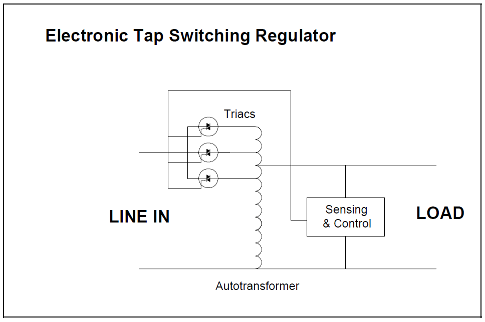
ELECTRONIC VOLTAGE REGULATOR
The voltage regulator was an electronic tap switching type (SCR gate driven) with a microprocessor control (shown in Figure 4). Tap switching regulators have very fast response time of approximately ½ cycle and are designed to filter input voltage variations. However, the regulators can trip when the output voltage exceeds 110% of nominal. This is generally done to protect the load from excessive overvoltage conditions.
This regulator was adversely affected by the transient caused by capacitor switching on the utility system.
SOLUTION
Power conditioning devices should never be more sensitive than the load that they are protecting. In this case, the transient was not severe enough to cause any damage to the chip testers. The regulator was the weak link.
One solution would be to replace the voltage regulator with a regulator with better filtering or to take it out completely. Regulation of this type may not be warranted.
Another solution would be to contact the manufacturer to see if the output overvoltage trip setting could be increased.
REFERENCES
G. Hensley, T. Singh, M. Samotyj, M. McGranaghan, and T. Grebe, Impact of Utility Switched Capacitors on Customer Systems Part II – Adjustable Speed Drive Concerns, IEEE Transactions PWRD, pp. 1623-1628, October, 1991.
G. Hensley, T. Singh, M. Samotyj, M. McGranaghan, and R. Zavadil, Impact of Utility Switched Capacitors on Customer Systems – Magnification at Low Voltage Capacitors, IEEE Transactions PWRD, pp. 862-868, April, 1992.
Electrotek Concepts, Inc., Evaluation of Distribution Capacitor Switching Concerns, Final Report, EPRI TR-107332, October 1997.
RELATED STANDARDS
IEEE Standard 1036
IEEE Standard 1159
GLOSSARY AND ACRONYMS
ASD: Adjustable-Speed Drive
PWM: Pulse Width Modulation
MOV: Metal Oxide Varistor
SCR: Silicon Controlled Rectifier
TVSS: Transient Voltage Surge Suppressors
