Published by Andrzej SOWA, Bialystok University of Technology, Faculty of Electrical Engineering
Abstract: Correctness estimation of lightning protection solutions require definition of lightning current distribution in conductive installations entering the structure during direct strike to lightning protection system of this structure. It concerns particularly this part of lightning current, which flows in electric installation. Information about this current gives the possibility to estimate the levels of overvoltages on the equipment’s ports and appropriate choose of surge protective devices. The calculations of this current in low-voltage power systems connected to different types of structures calculations were performed based on the circuit theory approach.
Streszczenie. Poprawny dobór rozwiązań ochrony odgromowej wymaga posiadania informacji o podziale prądu piorunowego w przewodzących instalacjach dochodzących do obiektu podczas bezpośredniego wyładowania w urządzenie piorunochronne. Szczególnie istotne jest określenie prądów udarowych występujących w instalacji elektrycznej. Wykorzystując metody obwodowe wyznaczono prądy wpływające do przewodów instalacji elektrycznych kilku różnych typów obiektów budowlanych (Prądy piorunowe w instalacji elektrycznej).
Keywords: surge protective device, lightning current, lightning protection, low-voltage power system
Słowa kluczowe: urządzenia ograniczające przepięcia, ochrona odgromowa, instalacja elektryczna
Introduction
During direct lightning strike to external lightning protection system (LPS) of structure the surge current flows on air-termination and down conductors into the earth and generate high potential which might lead to dangerous sparking between installations inside the structures.
To avoid such sparks all metal installations, low-voltage power system and date links at the entrance of the structure must be integrated into the equipotential bounding. In case of low-voltage power system LVPS, the protection against potential differences requires the surge protective devices SPD type 1. The arrangement of SPD should be places and montage in such manner, that their limited overvoltages to the levels which are required for low-voltage installation and for supply ports of devices. From the application point of view, it is interesting to evaluate the maximal values and shapes of surge currents in individual SPD during direct lightning strike to the LPS of structures.
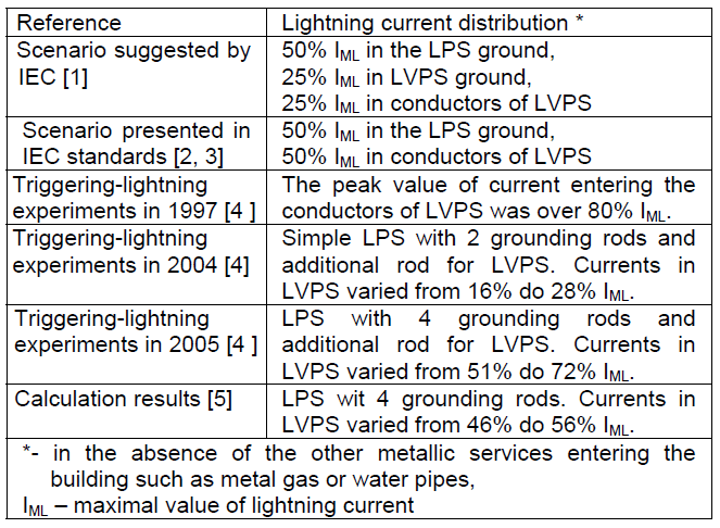
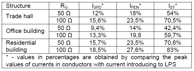
It was characteristic of the different analyses and measurements that these currents were a large part of total lightning current (Table 1).
Table 1. Lightning currents distribution during direct strike to LPS
In this paper, the great attention has been paid to develop suitable models for evaluating the lightning current distribution within the conductors of LVPS and especially the stress of individual SPD.
Models description
In paper only the low-voltage side of distribution system has been considered. Analyses were done for the LVPS with one stage protection systems – the arrangements with voltage-switching SPDs type 1 inside the structure. In theoretical consideration the model of SPD was realized on the base of switch with additional resistor, when the switch is closed. The spark-over voltages of SPDs were 1500 V and 2500 V.
Furthermore the impedances, such as inductances and resistances of the SPDs connections also are included. The LVPS was connected to the distribution transformer located outside the structure. The earthing impedance of the transformer is represented by L3 I R3 [6]. The basic of LVPS has been converted into equivalent circuit diagram presented in Fig.1.

In analysis the surge currents 100 kA and 150 kA (peak values) and shape 10/350μs were used for simulation the first lightning strokes.
This lightning current was described by typical equation [7]:
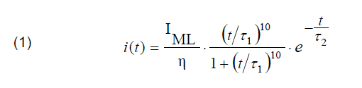
where: IML = peak values of current (100 kA or 150 kA), η = 0,930, 𝜏1 = 19 μs, 𝜏2 = 485 μs, t -time
Calculations were realized for LPS model of the trade hall with dimensions 48 m x 12 m x 12 m (case A). Down conductors were connected to simple earth electrodes type A with resistance RG = 6,4 Ω (Fig. 2).

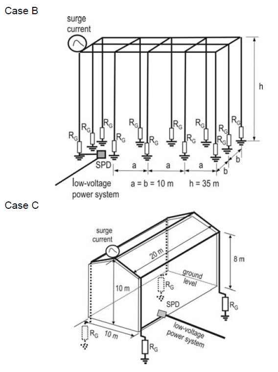
Additionally, the calculations were realized for LPS of 2 types of structures and the following conditions were considered:
Case B – office building (Fig. 3)
• lightning protection level II,
• base equal 20 m x 40 m and height h = 20 m,
• the mesh side of the air-termination system on the roof was 10 m x 10 m, and the distance between down conductors 10 m,
• conductors of LPS with radius 4 mm,
• surge currents were injected to the corners of LPS,
• earth termination system type A with earth electrode resistance RG = 10 Ω.
Case C – residential building (Fig. 3)
• lightning protection level IV,
• base 10 m x 20 m and maximal high 10 m,
• four down conductors at each edge of the structure,
• conductors of LPS with radius 4 mm,
• earth termination system type A with earth electrode resistance RG = 21 Ω.
Calculation results
Theoretical calculations of lightning current distribution are based on the simple circuit theory approach. In models, the conductive elements of LPS have been represented with an equivalent π model taking into account resistance and self-inductance, the inductance coupling with another segments and capacitance to the ground.
In the proposed models the influence of current in lightning channel between striking point and cloud were not considered. In calculation The Electromagnetic Transient Program EMTP [8] was used.
Examples of computed currents (case A) that flow to the earthing system of transformer through the PEN and phases conductors are shown in figure 4.
The overall division of lightning current is influenced by many factors. In calculations the following were considered:
• resistance R3 in range from 1 Ω to 20 Ω (Fig. 5 and 7).
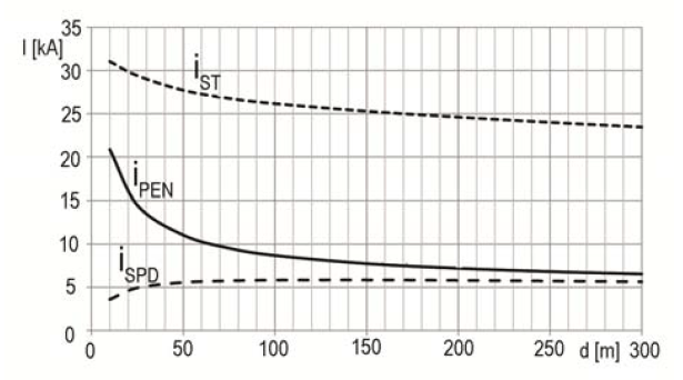
• distance d between transformer and SPDs from 10 m to 300 m (Fig. 6),
A reduction of the partials lightning currents in SPDs and PEN conductor can be achieved if the LVPS bounding bar is connected to additional grounding rod RAG. In calculations the values of RAG were the same like RG in LPS.
Changes in surge current distribution caused by additional grounding rods are presented in Fig. 5.
In order to comparison the effect of LPS on current distributions in conductors of LVPS calculations were realized with the same conditions in analyzed structures (values of RG, R3 = 5 Ω, distances d = 100 m and w = 5 m). Some results are presented in table 2.
Table 2. Maximal values of currents in conductors of LVPS
Conclusions
In this paper the results of numerical calculations of lightning currents in low-voltage power systems supplying different types of buildings during direct strikes to LPS were presented.
The knowledge of these currents may be great importance for an accurate determination of adequate SPD system in low-voltage installations inside the structures, more accurately than it can be done using the procedures suggested by international standards.
Further studies will be performed to correct models of SPD, low-voltage installations and load inside the structures.
REFERENCES
[1] Rakov V. A., Uman M. M., Mata C. T., Rambo k. J., Stapleton M.V., Sutil R.R., Direct Lightning Strike to the Lightning Protective System of a Residential Building: Triggered- Lightning Experiments. Trans. on Power Delivery, vol. 17, No. 2, 2002, p.575-586
[2] IEC 62305-3, Protection against lightning – Part 3: Physical damage to structure and life hazard.
[3] EN 61643-11, Surge protective devices connected to low-voltage systems.
[4] DeCarlo A., Rakov V. A., Jerauld J.E., Schnetzer G. H., Uman M., Schoene J.: Distribution of Currents in the Lightning Protective System of a Residential Building – Part I : Triggered Lightning Experiments. Trans. on Power Delivery, vol. 23, No. 4, 2008, p.2439-2446.
[5] Celli G., Ghiani E., Pilo F. A simulation tool for overvoltages brought inside a building through its grounding system. 26th International Conference on Lightning Protection, Cracow, Poland, 2002, 7b.2
[6] Birkl J., Zahlmann P.: Lightning currents in low-voltage power installation, 29th International Conference on Lightning Protection, Uppsala, Sweden, 2008, p. 10-1-1 – 10-1-25.
[7] IEC 62305-1, Protection against lightning – Part 1: General principles.
[8] ElectroMagnetic Transients Program (EMTP) Rule Book, http://www.eeug.org
Autor: dr hab. inż. Andrzej W. Sowa, prof. P.B., Politechnika Białostocka, Wydział Elektryczny, 15-351 Białystok, ul. Wiejska 45D, E-mail: Andrzej.sowa@ochrona.net.pl
Source & Publisher Item Identifier: PRZEGLĄD ELEKTROTECHNICZNY (Electrical Review), ISSN 0033-2097, R. 88 NR 9b/2012
