Published by Electrotek Concepts, Inc., PQSoft Case Study: Transient Voltages at an Industrial Facility Capacitor Switching, Document ID: PQS0505, Date: June 30, 2005.
Abstract: This case study describes concerns for capacitor switching transients within customer facilities. Magnification of transients initiated at higher voltage capacitors and tripping of sensitive variable frequency drive (VFD) loads are evaluated in particular.
The results of measurements and simulations associated with capacitor switching on the utility system and the resulting impacts at an industrial process plant are presented.
These results illustrate the important effect of customer load characteristics on the transients experienced within the facilities.
INTRODUCTION
Capacitor switching is considered a normal system event on the utility system and the transients associated with these switching operations are generally not a problem for utility system equipment. However, the transients can be magnified within customer facilities or can cause misoperation of sensitive electronic equipment, such as variable frequency drives (VFDs).
These concerns were evaluated in detail for a manufacturing facility. The transient overvoltages were simulated using the Electromagnetic Transients Program (EMTP) and field tests were performed to verify the modeling and evaluate the impact on actual plant loads.
Magnification of capacitor switching transients is perhaps the most important concern because the transient voltages can be very high and the energy levels associated with these transients can cause failure of electronic equipment and protective devices. Even without magnification, normal capacitor switching transients can cause problems with sensitive electronic loads. VFDs, in particular, can experience nuisance tripping for transient voltage magnitudes as low as 1.2 per unit.
This case focuses on field tests and simulations performed to evaluate the impact of switching capacitor banks on the transmission system supplying a facility and switching new capacitor banks installed at the distribution substation for the facility.
SYSTEM DESCRIPTION
The facility is supplied from a 115kV transmission system as shown in the representative online diagram provided in Figure 1. The main station that supplies the industrial customer includes two switched 48 MVAr shunt capacitor banks.
The service to the facility is through two 22.4 MVA, 115/12.47 kV substation transformers located on the site. The plant loads are then supplied from service entrance stations that step down to 480 Volts. The electrical loads at the facility consist primarily of motors (pumps and fans) and electronic loads. Most of the manufacturing equipment requires 120/208 V power which is provided through local step-down transformers serving individual loads or combinations of loads through a distribution panel. The most sensitive production equipment is supplied from large scale centralized Uninterruptible Power Supply (UPS) systems. These systems are connected in an on-line full capacity, parallel redundant configuration.
Power factor correction capacitors are not used within the facility. Therefore, magnification at low voltage capacitors is not a problem. In order to maximize capacity of the substation, the utility installed power factor correction capacitors at the 12.47 kV buses. The proposed configuration consisted of 7200 kVAr (6×1200 kVAr) at bus #2 and 3600 kVAr (3×1200 kVAr) at bus # 3. The addition of the substation capacitors prompted the concern for switching transient voltages within the plant. Transients during switching of either the 48 MVAr, 115kV banks or during switching of the individual 1200 kVAr steps were evaluated.
A preliminary model for use with the EMTP was developed to evaluate the concerns for capacitor switching transients. The model was built to accurately represent the system source equivalents at the transmission buses, transformers stepping down to the distribution substations, capacitor banks, and equivalents for loads at the facility and nearby utility buses.

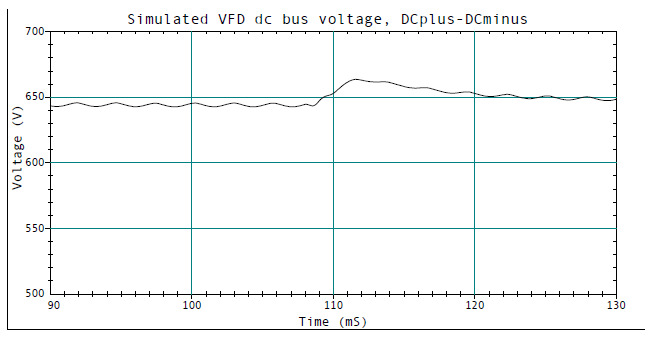
A VFD was modeled in detail (Figure 2) to evaluate the impacts of the capacitor switching transients on a typical VFD load. The main concern for the VFDs is that they will experience nuisance tripping caused by an increase in the dc bus voltage within the drive during a capacitor switching transient. The particular drives being evaluated had relatively high dc overvoltage trip settings of 850 Volts. This setting can be as low as 760 Volts for some drives. Previous publications have shown that the nuisance tripping caused by dc overvoltages can be solved by installing an isolating reactor (choke) in series with the drive. The drives being evaluated at the facility did not have chokes but were separated from the main 480 Volt supply by relatively long cable lengths.
The two 48 MVAr, 115kV capacitor banks have 0.3 mH series reactors to limit back-to-back switching inrush currents. The banks are switched with conventional SF6 breakers.
The new 12.47 kV capacitor consist of individual 1200 kVAr steps and series reactors to limit the inrush current during the back-to-back switching. The individual 1200 kVAr steps are switched with motorized air-break switches.

SIMULATION RESULTS
Simulations were performed using the model described to evaluate the expected transient voltages at the facility loads during capacitor switching at either 115 kV or 12.47 kV locations.
Energizing the 48 MVAr, 115kV Capacitor Banks
Switching of the 115 kV capacitor banks was being performed on a regular basis for some time prior to the addition of the 12.47 kV capacitors. This case results in a transient voltage at the facility that has been recorded by monitoring equipment on a number of occasions. Figure 3 is a typical case showing the transient voltage at a 480 Volt bus. These transients were not causing any problems at the facility.
The waveform in Figure 3 was used to estimate the damping being provided by the 115 kV transmission system and load equivalents. Figure 4 illustrates simulation results for the same case. The damping in the simulation case is somewhat less than the damping in the measured waveform that should result in conservative results from the simulations

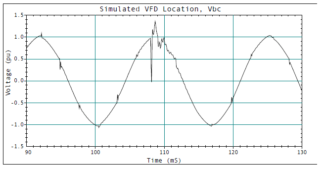
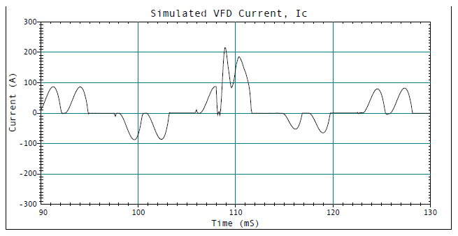
Energizing the 12.47 kV Capacitor Banks
This case involves the addition of power factor correction capacitor banks at the 12.47 kV buses. These capacitor banks are configured in 1200 kVAr steps. The first step to be energized results in the highest transient. The transients associated with energizing of subsequent steps are lower because the transient is shared with the other capacitors already in service. Figure 4-Figure 6 give the simulated transients at the 60 HP VFD load for energizing the first 1200 kVAr step. The transients are illustrated in per unit (pu). This is the actual voltage divided by the normal peak voltage magnitude. In Figure 4, the peak transient is approximately 1.3 pu, or about 880 Volts (L-L). The transient magnitude in the dc bus of the drive should be somewhat less than this due to current limiting impedances in the drive. Therefore, it is not likely that this transient would cause drive tripping.
FIELD TEST RESULTS
It was clear from the initial simulations that the potential for nuisance tripping of VFDs or other electronic loads existed during capacitor switching operations. Field tests were performed to evaluate the actual transient voltages at the facility during switching of the new 1200 kVAr capacitor banks and during switching of the 48 MVAr, 115kV capacitor banks. These tests were scheduled during maintenance shut down at the facility to minimize the impacts if any nuisance tripping was encountered.
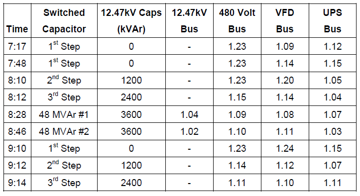
The test cases performed are summarized in Table 1 below. Basically, energizing operations for the three individual 1200 kVAr capacitor steps at the 12.47kV bus were evaluated first and then one of the 48 MVAr, 115kV banks was energized to evaluate the potential for magnification. Finally, the individual 1200 kVAr steps were de-energized and then put back into service.
For each of the test cases, the transient voltages were recorded at a number of locations. Two of the locations were selected to evaluate the impact of the transients at electronic loads. One site was a 60 HP VFD and the other load site was one of the main UPS installations. The 12.47kV bus was supplying these locations.
Table 1 – Summary of Field Measurements
SUMMARY
The simulations and measurements demonstrated the importance of plant loads in reducing capacitor switching transient voltages. Electronic loads and UPS systems can provide significant damping due to the capacitors and batteries that are effectively connected to the 480 volt bus through diodes or SCRs. These loads make up a significant portion of the total load at the facility.
Nuisance tripping of VFDs and other sensitive electronic loads can be a very important concern in industrial plants with continuous processes. Careful evaluation of the capacitor switching transients using digital simulations can indicate potential problems. However, it may be necessary to perform actual field measurements in cases where the expected transients are near the device limits. For the system studied, damping provided by system loads prevents nuisance tripping of the VFDs.
REFERENCES
S. S. Mikhail and M. F. McGranaghan, “Evaluation of Switching Concerns Associated with 345 kV Shunt Capacitor Applications,” IEEE Transactions PAS, Vol. 106, No. 4, pp. 221-230, April 1986.
G. Hensley, T. Singh, M. Samotyj, M. McGranaghan, and R. Zavadil, “Impact of Utility Switched Capacitors on Customer Systems – Magnification at Low Voltage Capacitors,” IEEE Transactions PWRD, pp. 862-868, April, 1992.
G. Hensley, T. Singh, M. Samotyj, M. McGranaghan, and R. Zavadil, “Impact of Utility Switched Capacitors on Customer Systems, Part II – Adjustable Speed Drive Concerns,” IEEE Transactions PWRD, pp. 1623-1628, October 1991.
RELATED STANDARDS
IEEE Std. 1036-1992
GLOSSARY AND ACRONYMS
ASD: Adjustable-Speed Drive
EMTP: Electromagnetic Transients Program
MOV: Metal Oxide Varistor
PWM: Pulse Width Modulation
TVSS: Transient Voltage Surge Suppressor
UPS: Uninterruptible Power Supply
