Published by Electrotek Concepts, Inc., PQSoft Case Study: Phase-to-Phase Transients at Transformer Terminations During Utility Capacitor Switching, Document ID: PQS0603, Date: January 1, 2006.
Abstract: There are a number of important transient related concerns when transmission capacitor banks are applied. These concerns include insulation withstand level, switchgear capabilities, energy duties of protective devices, and system harmonic considerations. The considerations should also be extended to include distribution systems and sensitive customer equipment. This case study presents a summary of the model development and simulations results for a phase-to-phase transients at transformer terminations evaluation.
INTRODUCTION
Energizing a shunt capacitor bank can subject three-phase transformers to excessive phase-to-phase and/or high frequency transients. The basic circuit configuration of concern consists of a three-phase transformer at one terminal of a radial line and a switched capacitor bank at the other terminal. The high phase-to-phase voltages are a result of traveling wave reflections at the transformer termination. It is possible to obtain transients approaching twice the peak system voltage on two phases with opposite polarity, resulting in a phase-to-phase transient of approximately four times the normal peak phase-to-ground voltage. These transients can easily exceed the phase-to-phase withstand capability of three phase transformers.
Figure 1 illustrates the simplified circuit used to investigate phase-to-phase transient voltages. Transient voltage problems at transformer terminations occur primarily with a delta primary winding fed radially from a capacitor location.
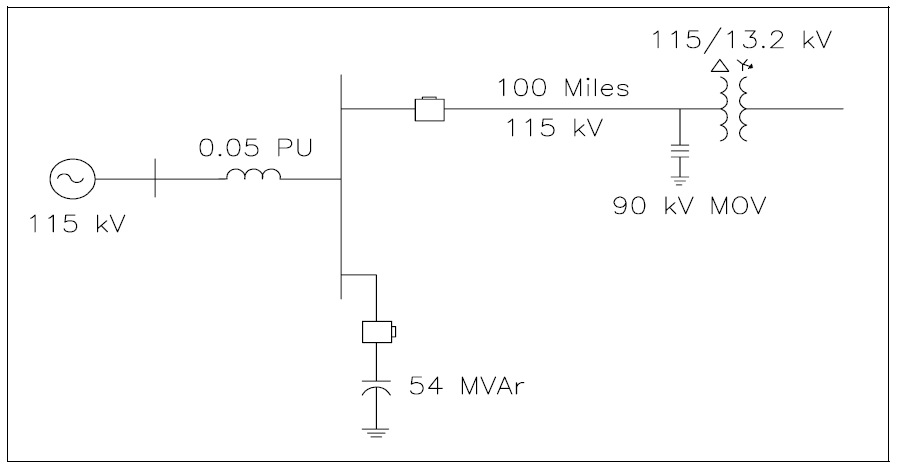
Xs = ( 1152/100 ) ∗ 0.05 = 6.6125Ω, Ls = 17.54mH
Xc = ( 1152/54 ) = 244.907Ω, C = 10.83μF
The transient voltages that can occur must be evaluated with respect to the transformer phase-to-phase insulation withstand capability. The IEEE Trial Use Standard (IEEE Std. 262B) for transformers specifies a phase-to-phase switching surge insulation level for transformers at 345kV and above. For transformers on 345kV systems, the recommended switching surge insulation level is 1050kV or 3.73 per-unit. No guidelines exist for lower voltage transformers. A worst-case assumption would be that the phase-to-phase insulation level is equal to the phase-to-ground insulation level.
MODEL DEVELOPMENT
The study of utility capacitor switching events frequently requires the use of sophisticated digital simulation tools. Simulations provide a convenient means to characterize transient events, determine resulting power quality problems, and evaluate possible mitigation methods. Quite often, they are performed in conjunction with system monitoring for verification of models and identification of important power quality concerns. The complexity of the models required for the simulations depends on the system characteristics and the transient event under investigation.
There are a number of important system variables that influence the phase-to-phase transient voltage magnitude that can occur at a transformer termination during capacitor switching. They include:
− Source characteristic: The source characteristic at the switched capacitor bank includes the short circuit capacity and the number of transmission lines entering the substation.
− Switched capacitor ratings: As with varying the source impedance, varying the switched capacitor ratings changes the frequency of oscillation that occurs when the capacitor is energized.
− Radial line length: The length of the transmission line between the capacitor bank and the transformer is important because it determines the length of time (and frequency) it takes a traveling wave to traverse the line.
− Transformer location along radial line: The highest traveling wave overvoltages during capacitor switching generally occur at radial line terminations. However, there are often a number of transformers tapped off the radial circuit. Usually, transformers along most of the line can be exposed to phase-to-phase transient voltages which may be excessive in terms of the transformer insulation.
− Surge arresters: Surge arresters located at the transformer can help protect the transformer from excessive phase-to-phase transients. The maximum phase-to-phase transient is equal to twice the arrester protective level when arresters are connected line-to-ground.
The phase-to-phase withstand strength of transformers on the system will depend on a number of factors; including transformer type, BIL rating, and construction. A worst-case assumption regarding the phase-to-phase withstand is that it is equal to the transformer phase-to-ground withstand level (which is determined directly by the BIL rating). This assumption is reasonable for delta-wye transformers used to supply distribution substations. It is likely that autotransformers will have greater phase-to-phase insulation strength because there are no windings connected directly across the phases.
The transmission line was represented using the following data (see Figure 2):
Voltage: 115 kV
Length: 100 miles
Tower: Double Circuit Steel
Phase Conductor:
1750 AA/61 (Jessamine)
O.D. = 1.525″
Rdc = 0.0523 Ω/mi
Ground Conductor:
3 #6 Alumoweld
O.D. = 0.349″
Rdc = 3.4468 Ω/mi
Earth resistivity = 55.28 Ω-meters
The transformer was modeled using the following data:
Rating: 12/16/20 MVA
Voltage: 115/13.2 kV
Connection: Delta / Wye-Gnd
Test Report Data:
Load loss watts: 45228 (three-phase)
No load loss watts: 16682 (three-phase)
Exciting current: 0.446% @ 100% voltage
Impedance: 6.83% @ 12 MVA
SIMULATION RESULTS
Figure 3, Figure 4, and Figure 5 illustrate the bus and transformer voltages (phase-to-ground and phase-to-phase) during energization of the 54 MVAr, 115kV capacitor bank with no MOV arresters in service. The energizing frequency for the capacitor bank is:
f = 1/2π√LC = 1/2π√(17.6mH∗10.8μF) = 365Hz
Figure 6 and Figure 7 show the transformer voltages (phase-to-ground and phase-to-phase) with a 90kV MOV in service on the transformer primary (connected phase-to-ground). The maximum phase-to-ground voltage was 1.78 per-unit and the maximum phase-to-phase was 3.57 per-unit

Note: 1pu = 115kV ∗ √2/√3
SUMMARY
Energizing a shunt capacitor bank can cause excessive phase-to-phase transients on transformers. The high phase-to-phase voltages are a result of traveling wave reflections at the transformer termination. It is possible to obtain transients approaching twice the peak system voltage on two phases with opposite polarity, resulting in a phase-to-phase transient of approximately four times the normal peak phase-to-ground voltage. These transients can exceed the phase-to-phase withstand capability of three phase transformers. MOV arresters and other overvoltage control methods (e.g., synchronous closing control, pre-insertion resistors/inductors, etc.) may be applied to reduce the magnitudes of the switching transients.
REFERENCES
- IEEE Standard 1032-1992, Guide for the Application of Shunt Power Capacitors, ISBN 1-55937-257-5.
- S. Mikhail and M. McGranaghan, Evaluation of Switching Concerns Associated with 345 kV Shunt Capacitor Applications, IEEE Transactions PAS, Vol. 106, No. 4, pp. 221-230, April, 1986.
- T.E. Grebe, Technologies for Transient Voltage Control During Switching of Transmission and Distribution Capacitor Banks, 1995 International Conference on Power Systems Transients, September 3-7, 1195, Lisbon, Portugal.
RELATED STANDARDS
IEEE Std. 262B
GLOSSARY AND ACRONYMS
BIL: Basic Impulse Level
BSL: Basic Switching Impulse Insulation Level
MOV: Metal Oxide Varistor
