Published by Electrotek Concepts, Inc., PQSoft Case Study: Feeder Lightning Transients, Document ID: PQS1101, Date: March 15, 2011.
Abstract: Lightning strokes to exposed utility transmission or distribution circuits can inject a significant amount of energy into the power system in a very short time, causing deviations in voltages and currents which persist until the excess energy is absorbed by dissipative elements (e.g., arresters). This case study presents a distribution feeder lightning transient overvoltage evaluation.
FEEDER LIGHTNING TRANSIENT CASE STUDY
A utility distribution system lightning transient analysis case study was completed for the system shown in Figure 1. The case study investigated the potential for severe high frequency transient overvoltages on distribution feeder primary and customer secondary buses during a lightning strike on the feeder primary. The power conditioning mitigation alternative of MOV surge arresters was also evaluated.
The simulations for the case study were completed using the PSCAD® program. A high-frequency transient model was created to simulate the lightning transients and resulting overvoltages and arrester energy duties. A high-frequency model was required to accurately represent the very high lightning transient frequencies. The lightning surge was assumed to be a current source with a very fast rise time (e.g., 8×20μsec).
The modeled circuit consisted of a 138 kV utility substation supplying a 50 MVA, 138kV/34.5kV substation transformer. A high frequency, distributed parameter transmission line model was required to accurately represent the traveling wave (reflections) effects during the lightning transient. Two 34.5 kV distribution feeders were included in the model. The first feeder consisted of 5-mile and 15-mile overhead feeder segments that were modeling using the distributed parameter transmission line model. The second feeder included 3-mile and 9-mile underground cable segments that were modeled using the frequency dependent cable model. Both line and cable constants were determined and the data was used to help validate the system model.
Traditional inductive transformer models generally look like an open circuit to the very high frequency lightning transients. Therefore, the 60 Hz transformer model can be improved by adding capacitances between windings and from the windings to ground. This type of model will act as a capacitive voltage divider to transfer a portion of the surge from the primary to the secondary windings. Bushing and winding capacitance values for the substation and customer step-down transformers were assumed based on typical data. Other substation equipment, such as circuit breakers and instrument transformers, are represented by their stray capacitances to ground. Typical stray capacitance values of substation equipment are provided in Annex B of IEEE Std. C37.011.
Lightning is a weather-related phenomenon that is often thought to be the principal cause of most high frequency transients. Energy from lightning strokes may enter the power system in several ways. A direct stroke to exposed equipment (e.g., overhead distribution feeder) is the most obvious. Because of the high-frequency and high-energy associated with a lightning flash, it is also possible for significant energy to be coupled into the power system from indirect strokes as well. Finally, in situations where more than one ground reference exists, it is possible for the potential difference generated by conduction of stroke current to ground to be conductively coupled into equipment. This can be especially important for computer and communications equipment.
Susceptibility of the power system to lightning is best characterized statistically, since the occurrence rate and stroke current magnitudes of lightning ground flashes is otherwise impossible to predict. Based on years of observations, the incidence of cloud-to-ground lightning flashes has been related to the level of thunderstorm activity, or isokeraunic level, in a general region. Magnitudes of lightning stroke currents range from 2 kA to 200 kA, although the probability of very small or very large magnitude is low. The average lightning surge current is approximately 30 kA.
When lightning strikes a portion of the power system directly, a voltage impulse equal to the product of the stroke current and the equivalent surge impedance of the power system will be created. The surge will propagate in all directions on the power system, dividing amongst all available paths at terminations. Energy may also be coupled into circuits that are not directly connected to the stricken system. The rapid rate-of-rise and high magnitude impulse will result in operation of surge arresters or flashover of line or equipment insulation. The high energy associated with a direct strike to the power system can easily exceed the withstand capability of surge arresters or other protective devices since they are not designed for this severe contingency.
Transient surges coupled into the power system from indirect strokes will propagate in a similar manner. While utility system protective equipment will operate properly and be able to withstand such an occurrence, there are mechanisms by which the effects of the indirect stroke can affect customer utilization equipment. High currents diverted into the grounding system by surge arresters will raise the potential of a local ground grid well above that of “true earth.” This “ground potential rise” (GPR) is of no consequence for equipment referenced only to the affected grid; there are situations however, where connections to remote ground references can result in misoperation or equipment damage under these conditions. Shielded communications and data circuits may be especially susceptible. Circuits connecting nearby buildings may be exposed to GPR should the building ground grids be separated electrically and one of them is struck by lightning. Under these conditions, an “isolated” computer ground can be a source of damaging or even lethal voltages and for this reason should never be used.
When evaluating these disturbances, it is important to remember that the stress on equipment is based on the impulse magnitude and duration plus the magnitude of the fundamental component at the instant of the impulse. The most common cause of impulsive transients is lightning. Due to the high frequencies involved, impulsive transients are generally damped quickly by resistive components in the circuit (e.g., conductor and transformer resistance). These transients are most prevalent very close to the disturbance that causes the transient (e.g., lightning, switching event, etc.) and there can be significant differences in the transient characteristic from one location within a facility to another.
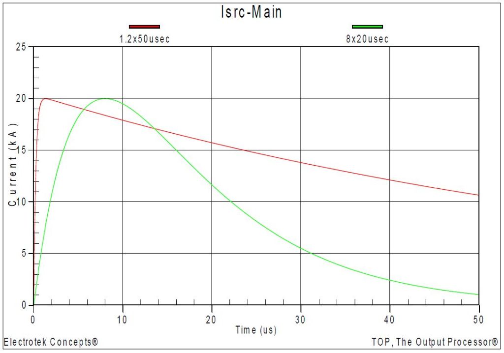
Figure 2 shows two representative lightning current waveforms commonly used in transient simulation studies. The figure shows a 20 kA—1.2×50 μsec and a 20 kA—8×20 μsec lightning stoke current characteristic. The simulation was completed using the PSCAD program.
The first simulation (Case 1) case involved a lightning strike to the 34.5kV feeder #1 at the Customer #1 primary bus (Phase A) with no MOV arresters included in the model. The specifications of the lightning current waveform were a 10 kA magnitude and an 8×20 μsec characteristic. The simulated lightning current waveform is shown in Figure 3.
Figure 4 shows the resulting feeder primary voltage for Case 1. The peak transient voltage with no arresters included in the model was 243.7 kV. The waveform illustrates voltage reflections from the ends of the overhead feeder and underground cable segments. Figure 5 shows the corresponding substation bus voltage, which has a peak voltage magnitude of 192.5 kV and Figure 6 shows the Customer #1 secondary bus voltage, which has a peak voltage of 3212.9 V.
A 27 kV MOV arrester was included on the primary winding of the Customer #1 transformer for Case 2. The assumed ratings for the arrester included:
Rated Voltage (Duty Cycle): 27 kV
Maximum Continuous Operating Voltage (MCOV): 24.4 kV
Maximum Energy Discharge Capability: 2.0 kJ/kVrated MCOV
Maximum Energy Discharge Capability: 48.8 kJ
10kA, 8×20μsec Discharge Voltage: 73.1 kV


Case 2 involved a lightning strike to the 34.5kV feeder #1 at the Customer #1 primary bus with the 27 kV MOV arrester included in the model. Figure 7 shows the resulting feeder primary voltage. The peak transient voltage with the arrester included in the model was 70.1 kV, which was approximately equal to the arrester’s 10 kA discharge voltage.
The simulated arrester energy duty was 8.0 kJ, which was approximately 16% of the assumed energy capability. Figure 8 shows the corresponding Customer #1 secondary bus voltage, which has a peak voltage of 961.5 V.
A low voltage surge arrester was included on the secondary winding of the Customer #1 transformer for Case 3. The assumed ratings for the arrester included:
Rated Voltage (Duty Cycle): 277 V
Maximum Continuous Operating Voltage (MCOV): 305 V
Maximum Energy Discharge Capability: 2,200 J
10kA, 8×20μsec Discharge Voltage: 910 V
Case 3 involved a lightning strike to the 34.5kV feeder #1 at the Customer #1 primary bus with both the primary and secondary arresters included in the model.
Figure 9 shows the resulting feeder primary voltage. The peak transient voltage with the primary arrester included in the model was 70.1 kV. Figure 10 shows the corresponding Customer #1 secondary bus voltage with the secondary arrester included in the model. The peak voltage was reduced from 961.5 V to 672.8 V. The energy duty for the secondary arrester was less than 10 J.


SUMMARY
This case study summarized a distribution feeder lightning transient overvoltage evaluation. A high-frequency transient model was created to simulate the lightning transients and resulting overvoltages and arrester energy duties. A high-frequency model was required to accurately represent the lightning phenomena. Surge arresters were evaluated as the power conditioning alternative.
REFERENCES
- “IEEE Recommended Practice for Monitoring Electric Power Quality,” IEEE Std. 1159-2009, IEEE, June 2009, ISBN: 978-0-7381-5940-9.
- “IEEE Application Guide for Transient Recovery Voltage for AC High Voltage Circuit Breakers Rated on a Symmetrical Current Basis,” IEEE Std. C37.011-1994, IEEE, ISBN: 1 55937-467-5.
- “Electrical Transients in Power Systems,” Allan Greenwood, Wiley-Interscience; Second Edition, April 18, 1991, ISBN: 0471620580.
- R.C. Dugan, M.F. McGranaghan, S. Santoso, H.W. Beaty, “Electrical Power Systems Quality,” McGraw-Hill Companies, Inc., November 2002, ISBN 0-07-138622-X.
RELATED STANDARDS
IEEE Std. 1159, IEEE Std. C37.011
GLOSSARY AND ACRONYMS
ASD: Adjustable-Speed Drive
CF: Crest Factor
DPF: Displacement Power Factor
PF: Power Factor
PWM: Pulse Width Modulation
THD: Total Harmonic Distortion
TPF: True Power Factor
