Published by Electrotek Concepts, Inc., PQSoft Case Study: Transformer Energizing and Dynamic Overvoltages, Document ID: PQS0709, Date: October 15, 2007.
Abstract: Energizing power transformers results in inrush currents that are rich in harmonic components. The inrush current interacts with the system impedance vs. frequency characteristics to create a voltage waveform that can have significant harmonic components for the duration that the inrush current is present.
Dynamic overvoltages are long-term resonant overvoltages lasting many cycles that can cause damage to capacitor units and other adjacent equipment, such as transformers and surge arresters.
This case study presents a transformer energizing and dynamic overvoltage evaluation for a 34.5kV distribution system.
INTRODUCTION
A transformer energizing and dynamic overvoltage evaluation was completed for the system shown in Figure 1.
BACKGROUND
Energizing saturable devices (devices with magnetic cores), such as power transformers, results in inrush currents that are rich in harmonic components. The inrush current interacts with the system impedance vs. frequency characteristics to create a voltage waveform that can have significant harmonic components for the duration that the inrush current is present. Transformer inrush current typically decays over a period on the order of one second.
This phenomenon combines concerns for harmonic current distortion and transient voltages. The harmonics of concern are low order (dominated by the 2nd through the 5th harmonics). If the circuit has a high impedance resonance near one of these frequencies, a dynamic overvoltage condition results that can cause failure of arresters and problems with sensitive equipment.
This problem is typically limited to cases of energizing large transformers with large power factor correction capacitor banks (e.g., arc furnace installations or other large industrial facilities). The solution to problems with dynamic overvoltages is to assure that the conditions causing the system resonance are not present when the transformer is energized. This could mean making sure a capacitor bank is out of service whenever a large transformer is energized.
Figure 2 shows an example measured current waveform on a 12.5kV feeder during a transformer energizing operation.
SIMULATION RESULTS
The accuracy of the system model was verified using three-phase and single-line-to-ground fault currents and other steady-state quantities, such as transformer, load, and capacitor bank rated currents and voltage rise.
The initial case (Case 1a) involved energizing the 18 MVA transformer using the high-side circuit breaker T1 with no secondary load or the 3.6 MVAr capacitor bank in-service on the 34.5kV bus. Figure 3 shows the worst-case simulated primary transformer current (Phase A) during energization of the unloaded transformer. The peak inrush current is nearly 175 amps. For reference, the full-load current for the transformer is approximately 45 amps. Figure 4 shows the corresponding secondary 34.5kV bus voltage waveform, which contains virtually no distortion.
Transformer inrush current is rich in 2nd, 3rd, 4th, and 5th harmonics. The exact characteristics of the inrush current are dependent on transformer parameters (e.g., saturation curve) and the initial condition of the residual transformer flux.
The second case (Case 1b) involved energizing the 18 MVA transformer using the high-side circuit breaker T1 with no secondary load and with the 3.6 MVAr capacitor bank in-service on the 34.5kV bus.
The resonant frequency for the 18 MVA transformer and the 3.6 MVAr capacitor bank may be approximated using the following expression:
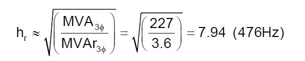
where:
hr = parallel resonant frequency (x fundamental)
MVA3φ = three-phase short circuit capacity (MVA = √3 * 34.5 kV * 3.8 kA ≈ 227 MVA)
MVAr3φ = three-phase capacitor bank rating (MVAr)
Figure 5 shows the worst-case simulated primary transformer current (Phase A) during energization of the unloaded transformer with the 3.6 MVAr capacitor bank in-service on the 34.5kV bus. Figure 6 shows the corresponding worst-case secondary 34.5kV bus voltage (Phase C).
As can be observed from the simulation results, the current waveform is much more distorted than the initial case that did not have the 3.6 MVAr capacitor bank in-service. In addition, the voltage waveform shows a resonance condition and the resulting dynamic overvoltage. Dynamic overvoltages are defined as long-term resonant overvoltages lasting many cycles that can cause damage to capacitor units and other adjacent equipment, such as transformers and surge arresters. Figure 7 shows the results of a Fourier analysis of the voltage waveform. The highest harmonic voltage component is at 480 Hz, which corresponds to the previous resonance calculation.
The final case (Case 1c) shows the effect of adding a secondary load on the 34.5kV bus, while still energizing the 18 MVA transformer using the high-side circuit breaker T1 with the 3.6 MVAr capacitor bank in-service. Figure 8 shows the worst-case simulated primary transformer current (Phase A) during energization of the loaded transformer with the 3.6 MVAr capacitor bank in-service on the 34.5kV bus. Figure 9 shows the corresponding worst-case secondary 34.5kV bus voltage (Phase C). As can be observed from the simulation results, the current and voltage waveforms are much less distorted with 5,000 kVA of resistive load included on the 34.5kV bus.
CONCLUSIONS
Observations and conclusions for this case study include:
− Transformer inrush currents contain harmonic currents that may produce dynamic overvoltages if the transformer is energized with a capacitor bank on the secondary bus.
− Solutions to this problem include energizing the capacitor bank separately from the transformer (this prevents the inrush current from exciting the resonant circuit) and energizing the transformer/capacitor combination with enough secondary load to sufficiently damp the transient overvoltage. The combination of switching an unloaded transformer and capacitor bank is the most susceptible to dynamic overvoltages.
RELATED STANDARDS
IEEE Std. 1036
GLOSSARY AND ACRONYMS
MOV: Metal Oxide Varistor Arrester
MSSPL: Maximum Switching Surge Protective Level
SiC: Silicon Carbide Arrester
