Published by Electrotek Concepts, Inc., PQSoft Case Study: Voltage Sag Study for a Distribution System Customer, Document ID: PQS0308, Date: February 4, 2003.
Abstract: Voltage variations, such as voltage sags and momentary interruptions are two of the most important power quality concerns for customers. Customers understand that interruptions cannot be completely prevented on the power system. However, they are less tolerant when their equipment mis-operates due to momentary disturbances which can be much more frequent than complete outages. Voltage variations and interruptions are inevitable on the power system. The most important of these variations occur during fault conditions on the power system.
This case presents the results of analysis of voltage sags caused by utility faults and their impact on a distribution system customer.
INTRODUCTION
Voltage variations, such as voltage sags and momentary interruptions are two of the most important power quality concerns for customers. Customers understand that interruptions cannot be completely prevented on the power system. However, they are less tolerant when their equipment misoperates due to momentary disturbances that can be much more frequent than complete outages. These conditions are characterized by short duration changes in the rms voltage magnitude supplied to the customer. The impact to the customer depends on the voltage magnitude during the disturbance, the duration of the disturbance, and the sensitivity of the customer equipment.
Voltage variations and interruptions are inevitable on the power system. The most important of these variations occur during fault conditions on the power system. Since it is impossible to completely eliminate the occurrence of faults, there will always by voltage variations to contend with. Power quality complaints occur either when the customer has equipment that is very sensitive to these voltage sags and is critical to the overall process or when the frequency of occurrence of the interruptions or sags is interpreted as being unacceptable.
On the utility system, protective systems are designed to limit damage caused by unusual events like faults or lightning strikes, and to localize the impact of such events to the smallest number of customers. This is accomplished with overcurrent protection devices, such as reclosers, sectionalizers, and fuses.
VOLTAGE SAG EVALUATION PROCEDURE
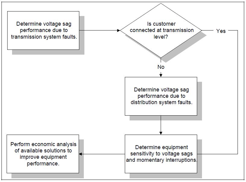
The most general approach to voltage sag analysis (illustrated in Figure 1) would characterize the system voltage sag performance by analyzing the fault performance on both the transmission and distribution systems. Computer calculations, using a short circuit analysis program, can be used to determine voltages around the system for any fault location. These calculations can be used to define an area of vulnerability for a particular customer. The likelihood of a fault can then be calculated from past fault records of the area, or from the fault performance of similar locations.
Voltage sags and momentary interruptions are often the most costly power quality variations affecting industrial and commercial customers. Faults over a wide area of the power system can affect the operation of a facility that has sensitive equipment. Faults can occur on the transmission system or on the distribution system. For most facilities, both cases need to be evaluated to estimate the overall performance expected. For facilities that are supplied directly from the transmission level, only transmission faults usually need to be considered.
Transmission System Performance
A significant number of end users are affected by faults on the transmission system. Therefore, one component of the total voltage sag performance at the end user location can be determined by the fault performance of the supplying transmission system. If the end user is supplied at a distribution level, the distribution system fault performance must also be evaluated. A standardized procedure may be used to determine the expected voltage sag performance at a selected bus on the system:
- Build a transmission line fault performance table: This table includes the historical performance information or expected performance for each line section in terms of number of faults expected per year for both single line-to-ground and three phase faults. Usually, single line-to-ground faults will be the most common.
- Calculate the area of vulnerability: Perform short circuit simulations to determine the voltage sag severity at selected system locations for fault locations throughout the transmission system. This will identify the fault locations that can cause a sag below a specified threshold. The total circuit miles of possible fault locations that can cause a sag severe enough to cause misoperation of end user equipment is known as the area of vulnerability for that equipment.
- Calculate expected number of voltage sags that will cause equipment misoperation: Convert the area of vulnerability data to actual expected events per month at the specified location. This is done using the area of vulnerability and the expected performance for three phase and single line-to-ground faults over that area. Summing up the expected number of faults on each line section within the area of vulnerability will give the total expected number of events that can cause equipment misoperation. This will usually be expressed as events per month or events per year.
- Calculate expected number of momentary interruptions: The momentary interruption performance for a customer due to transmission system faults should be calculated if the customer is supplied as a tap from a switched transmission line. In this case, the expected number of momentary interruptions per year due to transmission events is the expected number of faults on that line. This should be calculated separately from the voltage sag performance.
- Calculate the expected performance for different equipment sensitivity levels: This will give the end user information that can be used to help develop equipment specifications or to select equipment protection. The information can be presented as a histogram, or as a continuous curve of expected number of voltage sags vs. the sag severity. Equipment susceptibility levels may be determined from manufacturer data or testing.
End users that are supplied at distribution voltages will be impacted by faults on the distribution system as well as faults on the transmission system. Usually distribution end users must be concerned about both momentary interruptions and voltage sags caused by distribution faults and protective device operations.
The voltage sag performance data for the transmission and distribution systems will define the expected number of events of a specified severity that can be expected at the end user facility. This information must be evaluated with respect to the actual equipment sensitivity to determine the number of disruptions to the process or operation that can be expected per month or per year.
Voltage Sag Study
Figure 2 illustrates the oneline used the distribution system voltage sag study. The case illustrates the method for determining the three-phase and single-line-to-ground faults on a radial distribution feeder. Table 1 and Table 2 illustrate the data and output files for the system (equivalent @ bus 100).
Fault Current and Sag Magnitude Calculation
The first step in completing the study is to gather the positive and zero sequence impedance information and then convert each of these impedances to a common base (i.e. % @ 100 MVA). Often, this step will not be required since most utilities continuously maintain a datafile that represents their entire system, as well as equivalent impedances representing neighboring systems.
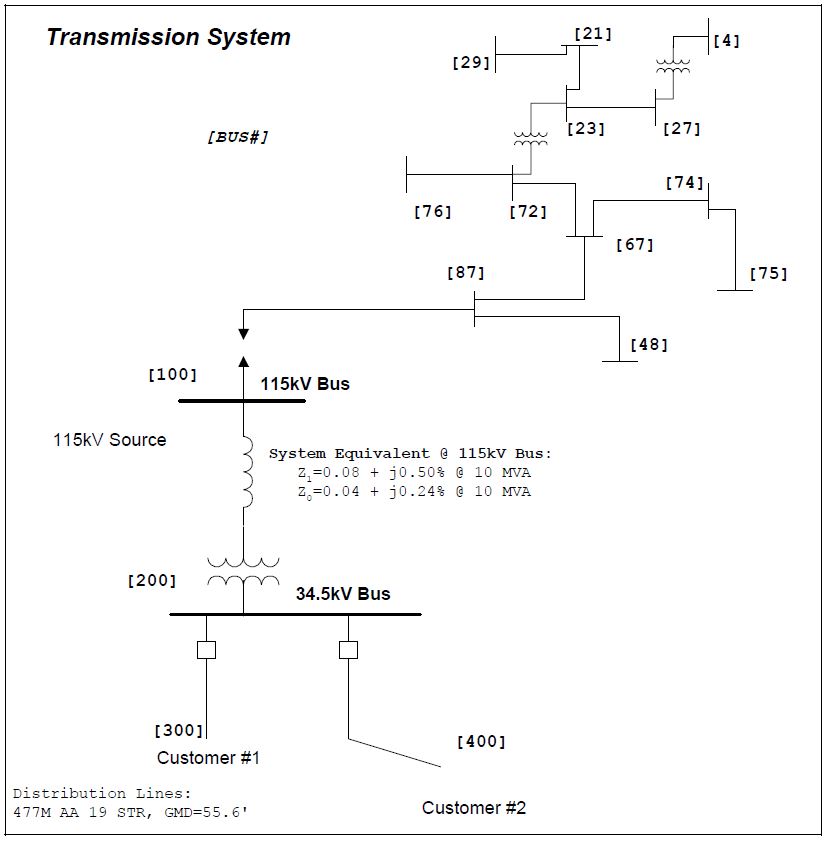
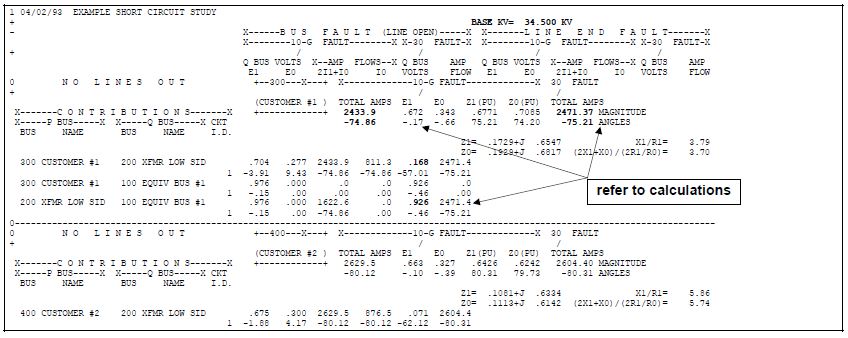
Table 1 – Data File for the Short Circuit Case

Table 2 – Output File for the Short Circuit Case
The impedance at the fault point is represented by the summation of the source, transformer, and distribution line. Table 3 summarizes the calculation.
Table 3 – Data Conversion for the Short Circuit Case
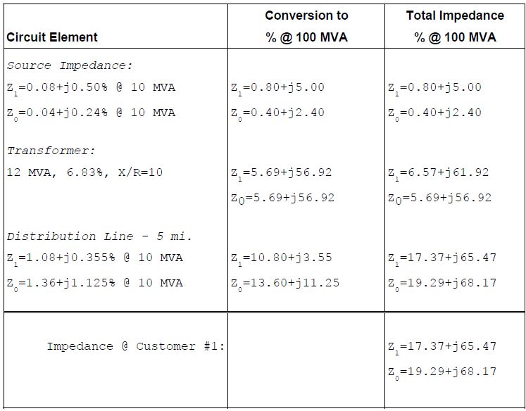
The impedance at the customer location (customer #1) is converted to ohms using the base impedance:
Zb = kV2 / MVA = 34.52 / 100 = 11.90Ω
Z1= 2.07 + j7.79 Ω [11.90 * (0.1737 + j0.6547 per-unit)]
Z0= 2.30 + j8.11 Ω [11.90 * (0.1929 + j0.6817 per-unit)]
The three-phase fault current at customer #1 can be determined using:
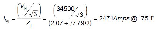
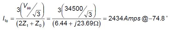
and the single-line-to-ground fault from:
The impedance at 115kV bus (equivalent source) is converted to ohms using the base impedance:
Zb = kV2 / MVA = 1152 / 100 = 132.25Ω
Z1= 1.06 + j6.62 Ω
Z0= 0.53 + j3.17 Ω
The 115kV bus voltage for the three-phase fault is approximated using:
V115 ≈ ( 115kV / √3 ) – [ 2471 (34.5 / 115) * 6.62Ω ] = 61.5kV (or 92.6%)
This corresponds to a 7.4% voltage sag for all other customers connected to the 115kV bus. The 34.5kV bus voltage for the three-phase fault is approximated using:
V34.5 = [ 34.5kV / √3 ] – [( 0.782 + j7.37Ω) • ( 2471< -75.1° A)] = 3.348kV (or 16.8%)
This corresponds to an 83.2% voltage sag for all customers connected to the 34.5kV bus.
Determining Fault Probability
The most frequent cause of voltage sags at a large industrial plant is lightning. Lightning is weather related, and the weather can be extremely variable from one season to another or one year to another. But over longer periods of time, weather will more closely follow certain patterns. Activities such as those by the National Lightning Detection Network are establishing the amount of lightning strokes a given area will receive over longer periods of time. The results of this work report on ground flash density (Ng) for all areas of the country. The ground flash density is a measure of lightning stokes to ground per square km per year. It is more accurate than the previously used isokeraunic level in determining the expected lightning performance of transmission lines. Isokeraunic level is the number of days per year lightning is heard, and must be multiplied by a proportionality factor to convert it to ground flash density. Utilizing geometry of the transmission lines, BIL levels of the insulators, and ground flash density, the expected number of faults per mile of line per year can be calculated. Table 4 provides the fault performance for the distribution customer.
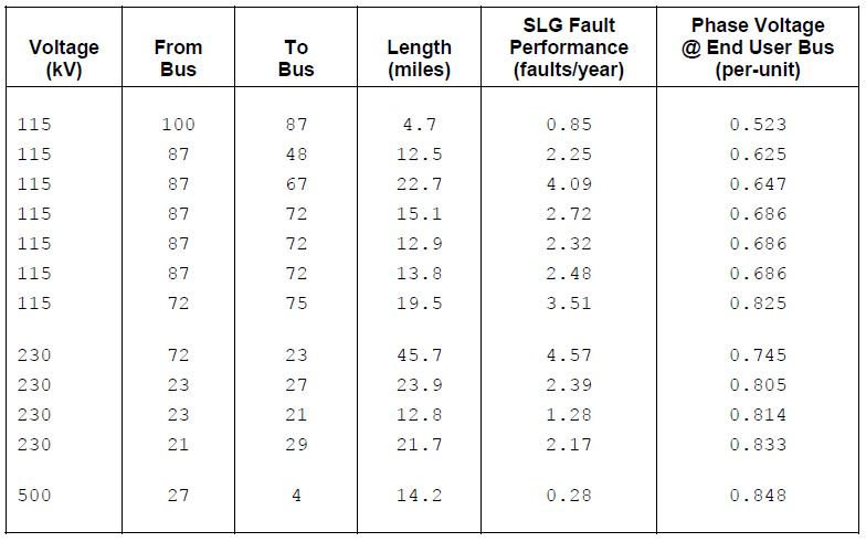
Determining Area of Vulnerability Characteristic
A number of short circuit simulations are performed to determine the voltage sag severity at a selected system location for fault locations throughout the transmission and distribution systems. This will identify the fault locations that can cause a sag below a specified threshold. The total circuit miles of possible fault locations that can cause a sag severe enough to cause misoperation of end user equipment is known as the area of vulnerability for that equipment. These calculations must include the effects of transformer and load connections as illustrated earlier. Table 4 shows the fault locations (single line-to-ground faults) that can cause voltage sags below 85% at the customer’s facility.
Table 4 – Area of Vulnerability Data
Determining Equipment Sensitivity
The customer’s facility is supplied by three-phase 480 volt feeders. The loads, and their respective sensitivities, can be categorized by type and connection to the power system:
− Motors, heating elements, and other three-phase loads can be connected directly to the 480 volt feeders: Sensitivity: 50% voltage > 1 cycle
− Adjustable-speed drives and other power electronic devices that use three-phase power will be connected directly to the 480 volt feeders, or through an isolation transformer.
Sensitivity: 85% voltage > 3 cycles
− Lighting often utilizes single-phase 277 volt connections from phase-to-neutral, or may use 480 volt or 120 volt single-phase connections.
Sensitivity: 70% voltage > 2 cycles
− Control devices such as computers, contactors, and programmable logic controllers utilize 480/120 volt single phase transformers for 120 volt control.
Sensitivity: 80% voltage > 3 cycle
The voltages experienced during a voltage sag condition will depend on the equipment connection. Some single-phase loads will be unaffected and other single-phase loads may drop out, even though their sensitivities to voltage sags may be identical. Different categories of equipment and even different brands of equipment within a category (e.g., two different models of adjustable speed drives) have significantly different sensitivities to voltage sags. In addition, it is important to recognize that the entire process in an industrial plant can depend on the sensitivity of a single piece of equipment. The overall process involves controls, drives, motor contactors, robotics, etc. that are all integral to the plant operation. This can also make it difficult to identify the sensitive piece of equipment after the entire process shuts down.
Determining the Number of Customer Events
The number of actual events that will impact the customer may be determined using the following steps:
- Calculate the area of vulnerability table. Perform short circuit simulations to determine the voltage sag severity at a selected system location for fault locations throughout the transmission system. This will identify the fault locations that can cause a sag below a specified threshold. The total circuit miles of possible fault locations that can cause a sag severe enough to cause misoperation of end user equipment is known as the area of vulnerability for that equipment. These calculations must include the effects of transformer and load connections.
- Calculate the expected number of voltage sags at equipment sensitivity levels. Convert the area of vulnerability data to actual expected events per month at the specified location. This is done using the area of vulnerability and the expected performance for three-phase and single line-to-ground faults over that area. Summing up the expected number of faults on each line section within the area of vulnerability will give the total expected number of events that can cause equipment misoperation. This will usually be expressed as events per month or events per year. illustrates a method for summarizing the results.
- Calculate the expected number of momentary interruptions. The momentary interruption performance for a customer due to transmission system faults should be calculated even if the customer is supplied from a transmission line. In that case, the expected number of momentary interruptions per year due to transmission events is the expected number of faults on that particular line. This should be calculated separately from the voltage sag performance.
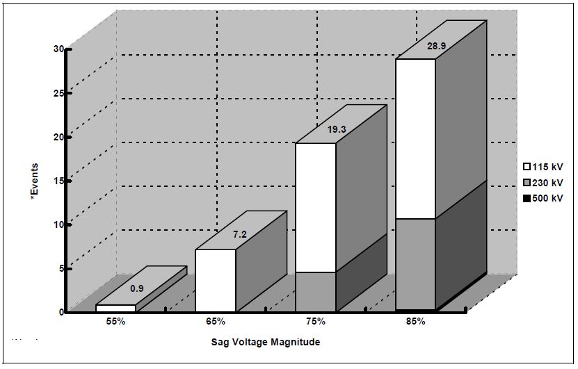
- Calculate the expected performance for various equipment sensitivity levels. This will give the customer information that can be used to help develop equipment specifications. The information can be presented as a histogram, as illustrated in Figure 3.
Table 5 – Expected Sag Performance
Location: Customer #2
Performance Calculation for a Threshold of: 85%
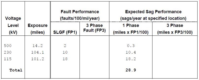
Therefore, if the customer has equipment that is affected by voltage sags of 85% and below, there should be on the average 28.9 events per year caused by single line-to-ground faults on the transmission system. The expected voltage sag performance for different values of voltage sag severity is shown in Figure 3.
Evaluating Solutions
There are three levels of possible solutions to voltage sag and momentary interruption problems:
- Power System Design: Faults on the power system are the ultimate cause of both momentary interruptions and voltage sags. Any measures taken to reduce the likelihood of a fault will help reduce the incidence of sags and interruptions to customers. These measures can include using underground circuits, tree trimming, and increased application of surge arresters for lightning protection on distribution circuits. On transmission circuits where lightning may be the most prevalent cause of faults, reducing tower footing resistances is one of the measures that can improve the lightning performance of lines.
- Equipment Design: It is possible to make the equipment being used in customer facilities less sensitive to voltage sags and momentary interruptions. Clocks and controls with low power requirements can be protected with a small battery or large capacitor to provide ride through capability. Motor control relays and contactors can be selected with less sensitive voltage sag thresholds. Controls can be set less sensitive to voltage sags unless the actual process requires an extremely tight voltage tolerance. This solution requires coordination with equipment manufacturers but the trend seems to be in the direction of increased ride through capability.
- Power Conditioning Equipment: This option involves the addition of power conditioning equipment at the individual loads that are sensitive to voltage sags and/or interruptions. The power conditioning requirements depend on the types of voltage sags that can be expected and the possible durations of interruptions.
SUMMARY
This case presents a general approach for voltage sag analysis by characterizing the system voltage sag performance due to faults on the utility system. Computer calculations, using a short circuit analysis program, can be used to determine voltages around the system for any fault location. These calculations can be used to define an area of vulnerability for a particular customer. This information, used in conjunction with equipment sensitivity, can be used to estimate the number of times a device will trip off-line each year.
REFERENCES
Electrical Distribution-System Protection, Third Edition, Cooper Power Systems, Pittsburgh, PA, 1990.
The Impact of Voltage Sags on Industrial Plant Loads, J. Lamoree, J.C. Smith, P. Vinett, T Duffy, and M.
Klein, Proceedings of the First International Conference on Power Quality (PQA ’91), Paris, France,
October, 1991.
Voltage Sag Analysis – Case Studies, J. Lamoree, D. Mueller, P. Vinett, and W. Jones, Proceedings of 1993 IEEE I&CPS Conference, St. Petersburg, Florida.
Industrial and Commercial Power System Analysis – Brown Book, IEEE Standard 399-1990.
RELATED STANDARDS
IEEE Standard P1531
GLOSSARY AND ACRONYMS
ASD: Adjustable-Speed Drive
