Published by Electrotek Concepts, Inc., PQSoft Case Study: Municipal Elevator Study – Improving Elevator Performance, Document ID: PQS0507, Date: September 30, 2005.
Abstract: In the past, system-wide voltage reductions and other voltage anomalies have caused unreliable elevator operation for some Municipal Utility customers. Municipal Utility’s Customer Service Department received many complaints from customers with elevators despite the fact that the voltage reductions were within standard guidelines and accepted practice. Investigation into these complaints resulted in the need for a more thorough research into the sensitivity of typical elevator systems.
Elevator shutdown due to system design and operation of elevator and drive system controls is the key problem experienced by the customers. It was believed that sustained voltage reduction for system load relief, rms variations because of feeder faults, and utility capacitor switching were among the voltage anomalies that have an effect on reliable elevator operation.
INTRODUCTION
System-wide voltage reductions on May 20-21, 1996 coincided with problems reported by some Municipal Utility customers. The 5% reduction on the 20th and the 8% reduction on the 21st resulted in over 100 complaints recorded by the Customer Service Department. Sixty-four of the customer complaints described erratic or unreliable elevator operation during these system-wide voltage reductions. The most important problem experienced by customers during the system-wide voltage reductions was complete elevator shutdown. As a result, Municipal Utility initiated a project to evaluate elevator operation because the voltage supplied during the system-wide voltage reductions was still above the service voltage recommended by American National Standard C84.1 (Electrical Power Systems and Equipment – Voltage Ratings – 60Hz). Several case studies were performed as part of the project to identify and correct the problems that customers experienced.
The project has identified voltage sags, inadequacy of service, and conversion to local rectification as causes for unreliable elevator operation. The study has also found that modernized elevators may experience erratic operation when supplied by an emergency generator, or the generator itself may experience erratic operation. Finally, the study found hydraulic elevators to be a special case and a potential cause of problems for other elevators and building electrical equipment.
VOLTAGE SAGS
The distribution system in the municipal customer service area is dynamic, yet reliable. In other words, it rarely experiences an interruption of power. Municipal Utility monitors the power quality of the supply network with Dranetz-BMI 8010 PQNodes (PQNodes). During the time of this study, 33 PQNodes were installed throughout the municipal’s system. The PQNodes were installed in 32 different locations.
The PQNodes recorded both steady state and transient data. This information was used in conjunction with input from customers to show correlation between power system events and erratic elevator operation. The PQNodes monitored both 208/120 volt systems and 480/277 volt systems in the municipal’s service area.
Municipal Utility assumed that the nominal voltages measured by the PQNodes were 125 and 277 volts. The PQNodes were setup to capture voltage sags of 0.90 per-unit (90%) and below. Voltages equal to or less than 112.5 volts on a 120 volt system and equal to or less than 249.3 volts on a 277 volt system were recorded as an event – a voltage sag or interruption. The PQNodes were also setup to capture voltage swells and transients of 1.10 per-unit and above. Voltages equal to or greater than 137.5 volts on a 120 volt system and equal to or greater than 304.7 volts on a 277 volt system were recorded as an event.
For the period from 1/1/94 to 1/22/98, 2,737 events were recorded. These events occurred on 718 different days. The events were compiled to show the number of events that were recorded and the magnitude and duration of these events. Figure 1 shows the voltage sags and interruptions that are less than 60 cycles in duration. The voltage sags that are included in Figure 1 account for 96% of all of the events recorded in the municipal customer service area from 1/1/94 to 1/22/98.

Voltage sags are one obvious cause of erratic elevator operation. The effects of voltage sags on industrial customers are well documented. Voltage sags at industrial sites are usually discussed with respect to the processes that the voltage sag interrupts and the product that is damaged or lost. The elevator is similar to an industrial process and the effect that the voltage sag has on the process depends on the installed elevator equipment and the point in the process that the elevator is at when the voltage sag occurs.
Voltage sags affect commercial customers in many ways. Voltage sags can result in downed computers and lost data, failure of broadcast and communication, blinking lights, and erratic elevator operation.
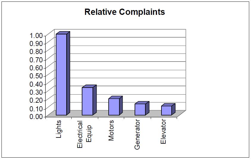
Customer feedback has provided information about how commercial customers are affected by the voltage sags that occur in the municipal customer service area. Figure 2 shows the relative number of customer complaints documented with respect to lighting, computers, air conditioning equipment, elevators, and other electrical equipment during events in the municipal customer service area. The values for the different types of equipment are relative to the 1,864 blinking light complaints.
Figure 2 also shows that abnormal elevator operation is not perceived as a problem nearly as often as the problem of blinking lights or abnormal operation of other electrical equipment. For the period of the study, elevator problems were reported 204 times.
Case studies showed that the elevator controls were more sensitive to voltage sags than the power conversion equipment. Since voltage sags are short duration events (reduction in rms voltage lasting between 0.5 cycles and 1 minute), the impact that voltage sags have on elevator operation is defined best by how the elevator passengers perceived the process of moving between floors. An elevator with good ride-through characteristics may not give the passengers any indication that a voltage sag had occurred. Another elevator may stop if the voltage sag is severe enough or long enough, but it resets itself and resumes operation when system voltage returns to normal. This would be perceived as erratic operation and an annoyance to the passengers because they reached their destination though there was a “glitch” in the process. However, some elevators must be manually reset after a voltage sag interrupts operation. This inability to automatically continue operation may result in the entrapment of passengers (and be perceived as much more than an annoyance).
Elevator controls that are required to be reset after being interrupted by a voltage sag should be replaced or retrofitted to allow the elevator to continue normal operation after the voltage sag. Another option for controls of this type is to protect the controls from the adverse effects of the voltage sag by installing power conditioning equipment.
INADEQUATE SERVICE
Inadequate service refers to the situation where a building has a load (kVA) demand greater than the designed service from the Municipal Utility. This situation results from the growth of the building’s base load without an upgrade in the service. System-Wide Voltage Reductions and Excessive Voltage Drop in Building Electrical System are included as sub-categories under the heading because they all ultimately affect the utilization voltage at the elevators.
System-Wide Voltage Reductions
System-wide voltage reductions on May 20 and 21, 1996, coincided with elevator problems reported by some Municipal Utility customers. The 5% reduction on the 20th and the 8% reduction on the 21st resulted in over 64 elevator complaints recorded by the Customer Service Department. An evaluation of the events, steady-state voltage, and customer reports for these two days showed that reliable elevator operation during a voltage reduction depends on service adequacy and acceptable voltage drop within the building’s electrical distribution system.
Figure 3 shows the steady-state voltage for one network for May 20-21, 1996. The chart also shows the times when elevator problems were reported to the Customer Service Department. The “Xs” shown on the X-axis represent recorded elevator problems.

Figure 3 shows that there were no voltage sags recorded in Network ‘A’ during this period, yet there were seven reports of elevator problems on May 21. The reports coincided with the 8% voltage reduction that was in effect for a short time in the middle of the day.
Figure 4 (see ANSI C84.1) shows the standard nominal system voltages and voltage ranges. Figure 4 shows that the Range A lower value is 114 volts on a 120 volt base, the Range B (Contingency) service voltage is as low as 110 volts. The average voltage supplied by Municipal Utility during the 8% voltage reduction was 114 volts. The recorded network voltage and the customer feedback indicate that voltage reductions contribute to conditions that adversely affect reliable elevator operation.

Case studies were performed to characterize the typical elevator utilization voltage. The case studies often showed that the building service was inadequate for the building load or that the voltage drop from the service entrance to the elevator machine rooms was excessive.
Excessive Voltage Drop in Building Electrical System
Case studies have shown that the voltage drop within some building electrical systems does not allow for reliable elevator operation for all of Municipal Utility’s operating contingencies. Some of the worst cases do not allow for normal service voltage variations. Figure 5 shows one of the worst examples of system voltage drop.
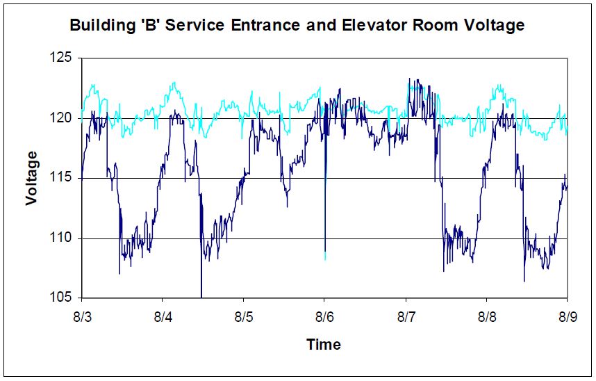
The chart shows the minimum service entrance and elevator room voltages for a 6-day period. Figure 5 shows that the utilization voltage at this site can be almost 10 volts lower than the voltage at the service entrance. These measurements show why this customer experienced erratic elevator operation even during Municipal Utility’s normal operating contingencies. Municipal Utility recommended that this customer upgrade their existing feeders or install additional feeders and divide the elevator load.
The National Fire Protection Association’s National Electrical Code (NFPA 70) provides examples of elevator feeder circuit design in Chapter 9. The procedure that NFPA 70 outlines should be revisited each time feeder or branch load is changed or increased. NFPA 70 recommends that the voltage drop for the feeder and branch circuit does not exceed 5% (6 volts on a 120 volt system). It is also important to take into account the voltage drop associated with other circuit components like transformers and reactors when evaluating the elevator utilization voltage.
CONVERSION TO LOCAL RECTIFICATION
The first step in converting a customer’s dc supply from the dc grid to local rectification is to determine what dc loads the customer actually has. The customer should collect elevator motor nameplate data and record the type of elevators that are being supplied (e.g., basement drum, overhead traction, geared or gearless, hydraulic, etc.). This step is necessary to ensure that the rectifier is large enough to supply the existing load. The starting current of most elevator machines is 1½ to 3 times the nameplate current. Some hydraulic elevator installations utilize dc motors. The starting current of a dc hydraulic elevator can be 7 to 10 times the nameplate current of the motor. The dc hydraulic elevator should not be assumed a trivial portion of the dc load because of the starting current.
Regeneration
Most elevators will regenerate power as a traction machine is operating an overhauling load. Regeneration occurs to some extent when the elevator car is slowed and brought to a stop.
Measurements have shown that a good rule-of-thumb is to assume that a dc elevator will regenerate up to 20% of its nameplate current.
The lack of connected dc load can prevent regenerated power from being absorbed and will result in the buildup of dc voltage. In some cases, this increase in voltage caused an increase in elevator speed and erratic operation of elevator controls. In the worst case, the voltage increased to the point of motor insulation failure and the failure of control components. It is critical that there is always sufficient load connected to the dc system to consume regenerated power.
A regeneration circuit should be installed with the local rectifier. In most cases, the specified regeneration circuit should be capable of absorbing the power regenerated by the largest motor in the supplied group, or it should be equal to 10% of the rectifier rating, whichever is larger. Regeneration circuits are typically load resistors that are always connected to the dc system or they are placed on line when the dc voltage reaches a set value.
Regeneration circuits made up of resistors that are always online are inefficient, costly, and can be physically large. Regeneration circuits that are placed online as required are typically smaller, less expensive to purchase and less costly to operate over the long term than fixed resistor banks.
Controlled Versus Uncontrolled Rectifiers
Customers have options when purchasing and installing local rectifiers. One of these options is to install a controlled rectifier instead of an uncontrolled rectifier. Controlled rectifiers may appear to offer the customer some flexibility that an uncontrolled rectifier does not, but the controlled rectifier supplies dc voltage that is not always as smooth as the voltage supplied by an uncontrolled rectifier.
In one case, a customer experienced erratic elevator operation after a controlled rectifier was installed to supply dc power to the elevators in their building. Investigation of the erratic operation showed that the ripple that was present in the output of the controlled rectifier was causing various dc relays to operate improperly.
Figure 6 shows the output of a traditional uncontrolled rectifier and Figure 7 shows the output of a controlled rectifier.


This customer solved their erratic control problems by filtering and smoothing the supply voltage to the elevator controls.
EMERGENCY GENERATORS
Elevator operation (particularly modernized elevators) on emergency generators presents problems that many customers have not considered. The emergency generator is a much weaker source (lower available short-circuit current) than the normal Municipal Utility supply. The building power system is much more dynamic with emergency generators supplying power. In addition, harmonic voltage distortion is typically higher and voltage regulation is generally poorer with emergency generators supplying power. Most of the problems associated with elevator operation on emergency generators are often related to elevator modernizations and electronic drives and regeneration.
Modernizations and Harmonic Distortion
Modernizing older elevator machines to electronic drives provides the customer with many benefits. Unfortunately, some modernizations introduce new power quality-related concerns. Harmonic distortion can cause erratic operation of generator controls and regulators and can adversely affect the operation of other emergency loads.
There are no fixed rules for supplying electronic elevator loads with generators. Each application needs to be evaluated as a unique case. Measurements, testing, and simulations are useful tools in determining the impact that electronic drive operation can have on emergency generator operation.
Some solutions and recommendations from different case studies include:
- De-sensitize generator controls using isolation transformers or filters.
- Install a harmonic filter at a common emergency bus to lower the total harmonic voltage distortion on the emergency power system.
- Install filters at the harmonic producing loads.
- Configure the elevator controls, when possible, to limit the number of elevators that can operate at any time.
- Remove unnecessary elevators from the emergency power system.
Modernizations and Regeneration
Electronic drives are not only efficient at converting power for use by the elevator motor they are efficient at regenerating power during overhauling conditions. Motor-generators absorb some of the regenerated power and do not present the regeneration problems that an electronic drive can.
The Institute of Electrical and Electronics Engineers Standard 241-1990, “Recommended Practice for Electric Power Systems in Commercial Buildings,” (IEEE Gray Book) provides the following calculations for determining the regenerated power for variable voltage gearless machines:
- Running full-load down = Approximately 40% of running full load up at a 40% negative power factor.
- Stopping full-load down = Approximately 50% of starting full load up at a 50% negative power factor.
There are many different opinions about sizing, or over sizing, generators to reliably handle regenerated power. It is generally not recommended to use regenerated power as a criterion for sizing emergency generators. When an emergency generator is supplying loads capable of regeneration, a regeneration circuit should be sized and installed to absorb the regenerated power. Regeneration circuits should be an integral part of new generator installations and regeneration circuits can be easily installed at existing generator sites.
HYDRAULIC ELEVATORS
Case studies that involve hydraulic elevators tend to be classic cases of voltage sags due to motor starting. The starting characteristics of hydraulic elevator motors are similar to other pump motors. Hydraulic elevators are often used in low rise and freight applications where their simplicity and low maintenance costs more than compensate for their slow speed. The controls are rarely more sophisticated than an across-the-line motor starter with start, stop and jog capability. The starting current of a hydraulic elevator is approximately seven to ten times the nameplate current of the motor.
The high starting current of a hydraulic elevator can aggravate the power quality problems that exist in any commercial building. Hydraulic elevator starting can cause a noticeable disturbance in a commercial building during periods of peak load.
Customers can minimize the adverse affects of hydraulic elevator starting by ensuring that the building service is adequate and that the feeder and branch circuit supplying the elevator(s) is adequate. Sometimes circuits can be reconfigured to isolate sensitive loads from the circuit that supplies the hydraulic elevator. Some customers are able to limit the use of hydraulic elevators to times off peak and outside the working hours of building tenants. In addition, some new products have become available that are well suited to minimizing the voltage sag created by motor starting.
SUMMARY
Several case studies were performed at commercial sites as part of a project to identify and correct the problems experienced with elevator operation. The case studies identified voltage sags, inadequacy of service, and conversion to local rectification as causes for unreliable elevator operation. The case studies also showed that modernized elevators may experience erratic operation when supplied by an emergency generator, or the generator itself may experience erratic operation. Finally, the study has also found hydraulic elevators to be a special case and a potential cause of problems for other elevators and building electrical equipment.
The elevator is similar to an industrial process and the effect that the voltage sag has on the process depends on the installed elevator equipment and the point in the process that the elevator is at when the voltage sag occurs. Case studies showed that elevator controls were more sensitive to voltage sags than the power conversion equipment. Elevators that ride through a voltage sag or can automatically resume normal operation after a voltage sag are preferable to elevators that must be manually reset. Elevator systems that must be manually reset are more likely to entrap passengers.
Reliable elevator operation during a voltage reduction depends on service adequacy and acceptable voltage drop within the building’s electrical distribution system. Case studies have shown that the voltage drop within some building electrical systems does not allow for reliable elevator operation for all of Municipal Utility’s operating contingencies. Some of the worst cases do not allow for normal service voltage variations.
Most elevators will regenerate power as a traction machine is operating an overhauling load. The lack of connected dc load can prevent regenerated power from being absorbed and will result in the buildup of dc voltage. It is critical that there is always sufficient load connected to the dc system to consume regenerated power. A regeneration circuit should be an integral part of any local rectifier installation where regenerated power is a concern. Regeneration circuits should also be an integral part of emergency power systems where emergency generators supply regenerative elevator loads.
Harmonic distortion can cause erratic operation of generator controls and regulators and can adversely affect the operation of other emergency loads. Measurements, testing, and simulations are useful tools in determining the impact that electronic drive operation can have on emergency generator operation.
The high starting current of a hydraulic elevator can aggravate the power quality problems that exist in any commercial building. Customers can minimize the adverse affects of hydraulic elevator starting by ensuring that the building service is adequate and that the feeder and branch circuit supplying the elevator(s) is adequate.
Commercial customers need to consider the impact that additional load has on building power system service and reliability. It can be beneficial to have a third party evaluate the elevator modernization with respect to the power system.
REFERENCES
American Society of Mechanical Engineers Safety Code for Elevators and Escalators. (ASME A17.1-1996).
Institute of Electrical and Electronics Engineers standard 241-1990 –“Recommended Practice for Electric Power Systems in Commercial Buildings.” (IEEE Gray Book).
National Fire Protection Association’s National Electrical Code. (NFPA 70).
National Electrical Manufacturers Association’s standards publication #MG 1-1993. (NEMA MG1).
American National Standard C84.1-1995 – “Electrical Power Systems and Equipment – Voltage Ratings (60Hz).” (ANSI C84.1).
Institute of Electrical and Electronics Engineers Standard 242-1986 –“Protection and Coordination for Industrial and Commercial Power Systems.” (IEEE Buff Book).
P.J. Welch, “Elevator Guidelines for Emergency Generators,” Elevator World, March 1998.
RELATED STANDARDS
ANSI Std. C84.1
NFPA 70 National Electric Code
ANSI/IEEE Std. 141 Industrial Electric Power Systems
ANSI/IEEE Std. 241 Commercial Electric Power Systems
ANSI/IEEE Std. 399 Industrial & Commercial Power System Analysis
ANSI/IEEE Std. 446 Industrial & Commercial Power System Emergency Power
ANSI/IEEE Std.493 Industrial & Commercial Power System Reliability
