Published by K. B. Mohd. Umar Ansari1, Manjeet Singh2, Sandeep Kumar3
B.E (EEE), M.Tech (Electrical Power & Energy Systems), Ex- Engineer – GET, Tata Motors Pvt. Ltd., Sector 11,
Udham Singh Nagar, Pantnagar, UK, India. 1
B.Tech (EN), Ex-Electrical Engineer, Flowmore Limited, Sahibabad, Ghaziabad, U.P., India2
B.Tech (EE), M.Tech (Power Systems*), Lecturer, Department of Electrical Engg, Sri RamSwaroop Memorial
University, Lucknow, U.P., India3
Published in International Journal of Advanced Research in Electrical, Electronics and Instrumentation Engineering (A High Impact Factor , Monthly, Peer Reviewed Journal)
Website: http://www.ijareeie.com
Vol. 7 , Issue 10, October 2018
ABSTRACT: Wind power industry is developing rapidly; more and more wind farms are being connected into power systems. Integration of large scale wind farms into power systems presents some challenges that must be addressed, such as system operation and control, system stability, and power quality. This paper discuss the impact of wind turbine generation systems operation connected to power systems, describes the main power quality parameters and requirements on such generations. Furthermore, it deals with the complexities of modelling wind turbine generation systems connected to the power grid, i.e. modelling of electrical, mechanical and aerodynamic components of the wind turbine system, including the active and reactive power control. In order to analyze power quality phenomena related to wind power generation, digital computer simulation is required to solve the complex differential equations.
KEYWORDS: Wind Turbines, Wind farms, Power quality, Wind power generation, Stability, Grid code, Connection requirements
I.INTRODUCTION
Wind turbine technology has undergone a revolution during the last century. A wind turbine is a machine for converting the kinetic energy in the wind into mechanical energy and mechanical energy is then converted into electricity. The machine which converts mechanical energy into electrical energy is called wind generator or aero generator. If the mechanical energy is used directly by machinery, such as a pump or grinding stones, the machine is called a windmill. A WECS (Wind Energy Conversion System) is a structure that transforms the kinetic energy of the incoming air stream into electrical energy. This conversion takes place in two steps, as follows. The extraction device, named wind turbine rotor turns under the wind stream action, thus harvesting a mechanical power. The rotor drives a rotating electrical machine, the generator, which outputs electrical power.
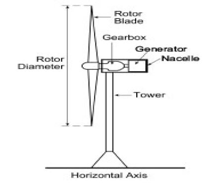

Wind turbines are classified into two general types: horizontal axis and vertical axis. A horizontal axis machine has its blades rotating on an axis parallel to the ground as shown in Fig. 1.1. A vertical axis machine has its blades rotating on an axis perpendicular to the ground as shown in Fig. 1.2. Today, the vast majority of manufactured wind turbines are horizontal axis with two or three blades.
PARTS OF WIND TURBINE

Fig. 1.3 illustrates the major components placement in horizontal axis wind turbine.
A typical wind turbine consists of the following components:
BLADE– An important part of a wind turbine that extracts wind energy.
HUB– Blades are fixed to a hub which is a central solid part of the turbine.
GEAR BOX– Two types of gear box are used in wind turbine- Parallel shaft-It is used in small turbines, design is simple, maintenance is easy, high mass material and offset shaft. Planetary shaft- It is used in large turbines, complex design, low mass material and in line arrangements.
BRAKES-Two independent brake sets are incorporated on the rotor low speed shaft and high speed shaft The low speed shaft brake is Hydraulic operated .The high speed shaft brake is self adjusted and spring loaded.
NACELLE– The nacelle houses the generator, the gearbox, the hydraulic system and yawing mechanism.
GENERATOR– The conversion of mechanical power of wind turbine into the electrical power can be accomplished by one of the following type of the electrical machine- Synchronous machine 2. Induction machine
TOWER– Towers are made from tubular steel, concrete or steel lattice. Because wind speed is getting higher with the height, taller towers enable turbines to capture more energy and this way generates more electricity.
II.A METHODOLOGY FOR COMPATIBILITY EVALUATION OF WIND GENERATION INTEGRATION IN POWER SYSTEMS
At the present time and in the near future, generators for wind turbines will be synchronous generators, permanent magnet synchronous generators, and induction generators, including the squirrel cage type and wound rotor type. For small to medium power wind turbines, permanent magnet generators and squirrel cage induction generators are often used because of their reliability and cost advantages. Induction generators, permanent magnet synchronous generators and wound field synchronous generators are currently used in various high power wind turbines. Interconnection apparatuses are devices to achieve power control, soft start and interconnection functions. Very often, power electronic converters are used as such devices. Most modern turbine inverters are forced commutated PWM inverters to provide a fixed voltage and fixed frequency output with a high power quality. Both voltage source voltage controlled inverters and voltage source current controlled inverters have been applied in wind turbines. For certain high power wind turbines, effective power control can be achieved with double PWM (pulse width modulation) converters which provide a bi-directional power flow between the turbine generator and the utility grid. In order to analyze wind generation compatibility in power systems four factors may be taken into account:
- Electrical power system characteristics (GRID)
- Wind turbine technology (WIND FARM)
- Grid connection requirements
- Simulation tools

POWER GENERATION SYSTEM
The electrical power generation structure contains both electromagnetic and electrical subsystems. Besides the electrical generator and power electronics converter it generally contains an electrical transformer to ensure the grid voltage compatibility.
FIXED-SPEED WECS
Fixed-speed WECS operate at constant speed. That means that, regardless of the wind speed, the wind turbine rotor speed is fixed and determined by the grid frequency. Fixed-speed WECS are typically equipped with squirrel-cage induction generators (SCIG), soft starter and capacitor bank and they are connected directly to the grid, as shown in Fig.1.4.

SCIG were preferred because they are mechanically simple and have low maintenance cost. SCIG-based WECS are designed to achieve maximum power efficiency at a unique wind speed. In order to increase the power efficiency Fixed-speed WECS have the advantage of being simple, robust and reliable, with simple and inexpensive electric systems and well proven operation. On the other hand, due to the fixed-speed operation, the mechanical stress is important and full wind power is not extracted.
An evolution of the fixed-speed SCIG-based WECS are the limited variable speed WECS. They are equipped with a wound-rotor induction generator (WRIG) with variable external rotor resistance as shown in Fig. 1.5. The unique feature of this WECS is that it has a variable additional rotor resistance, controlled by power electronics. Thus, the total (internal plus external) rotor resistance is adjustable, further controlling the slip of the generator and therefore the slope of the mechanical characteristic.

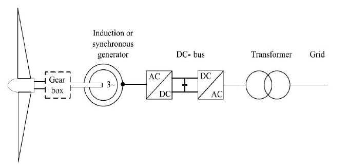
VARIABLE SPEED WECS
Variable-speed wind turbines are currently the most used WECS. The variable speed operation is possible due to the power electronic converters interface, allowing a full (or partial) decoupling from the grid. The doubly-fed-induction-generator (DFIG) based WECS shown in Fig. 1.6, also known as improved variable-speed WECS, is presently the most used by the wind turbine industry.
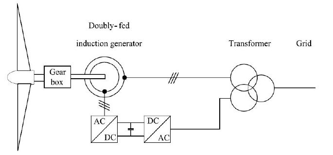
The DFIG is a WRIG with the stator windings connected directly to the three phase, constant-frequency grid and the rotor windings connected to a back-to-back (AC–AC) voltage source converter. Thus, the term “doubly-fed” comes from the fact that the stator voltage is applied from the grid and the rotor voltage is impressed by the power converter. The power electronics converter comprises of two IGBT converters, namely the rotor side and the grid side converter, connected with a direct current (DC) link. The rotor side converter controls the generator in terms of active and reactive power, while the grid side converter controls the DC-link voltage and ensures operation at a large power factor. The stator outputs power into the grid all the time. The rotor, depending on the operation point, is feeding power into the grid when the slip is negative (over synchronous operation) and it absorbs power from the grid when the slip is positive (sub-synchronous operation). In both cases, the power flow in the rotor is approximately proportional to the slip. DFIG-based WECS are highly controllable, allowing maximum power extraction over a large range of wind speeds.
III.GRID CONNECTION REQUIREMENTS
The connection of wind generation to electrical power systems influences the system operation point, the load flow of real and reactive power, nodal voltages and power losses. At the same time wind power generation has various characteristics with a wide spectrum of influence which are listed below [9]:
- Location in the power system
- Voltage variation of amplitude and frequency
- Flicker
- Harmonics
- Short circuit currents and protection systems
- Stability
- Self-excitation of asynchronous generators
- Real power losses
The rising impact of wind power generation in power systems cause system operators to extend grid connection requirements in order to ensure its correct operation. We can divide grid connection requirements into two categories:
- General grid code requirements
- Special requirements for wind generation
The first category represents requirements valid for every generator in the grid. These are general requirements regarding the system operation point. Some of the most important grid code requirements are:
- Steady state voltage variation
- Line capacity
- Short circuit power at the connection point
- Frequency variations
- Protection
- Contingency
Special requirements for wind generation were introduced to insert wind power generation in the power system without an impact on power quality or system stability.
There are two different types of requirements: requirements established by system operators and national or international standards.
The control of reactive power at the generators is used in order to keep the voltage within the required limits and avoid voltage stability problems. Wind generation should also contribute to voltage regulation in the system, the requirements either concern a certain voltage range that should be maintained at the point of connection or certain reactive power compensation that should be provided.
Until now in case of short-circuits or instability of the grid the wind parks disconnected immediately from the power system. Due to the high penetration of wind generation system operators observe a certain risk for the system stability during major disconnections. Therefore in the new regulations require that wind farms stay connected during a line voltage fault and participate in recovery from the fault.
National and international standards are applied to wind power generation regarding power quality issues for the emission of disturbances in the power system by wind generators.
IV. WIND FARMS OPERATION AND CONTROL, STABILITY IMPROVEMENT
In this section some possible methods of control options are discussed.

Mechanical Control of the turbine blade: As the wind speed changes the pitch of the blades or blade tip is adjusted to control the frequency of the turbine rotation.
The drawback of this method is that power in the wind is wasted and control method can be expensive and unreliable.
Load control: As the wind speed changes the electrical load is changed by rapid switching, so the turbine frequency is controlled. This method makes greater use of power in the wind because the blade pitch s kept at the optimum angle.
The advantages and disadvantages of WTIG are shown in table 1 below:
| Generator Concept | Advantages | Disadvantages |
|---|---|---|
| SCIG | Easier to design, construct and control Robust operation Low cost | Low energy yield No active/reactive power controllability High mechanical stress High losses on gear |
| PMSG | Highest energy yield Higher active/reactive power controllability Absence of brush/slip ring Low mechanical stress No copper loss on rotor | High cost of PM material Demagnetization of PM Complex construction process Higher cost on PEC Higher losses on PEC Large size |
| DFIG | High energy yield High active/reactive power controllability Lower cost on PEC Lower losses by PEC Less mechanical stress Compact size | Existence of brush/slip ring High losses on gear |
Stability support
System stability is largely associated with power system faults in a network such as tripping of transmission lines, loss of production capacity (generator unit failure) and short circuits. These failures disrupt the balance of power (active and reactive) and change the power flow. Though the capacity of the operating generators may be adequate, large voltage drops may occur suddenly. The unbalance and re-distribution of real and reactive power in the network may force the voltage to vary beyond the boundary of stability. A period of low voltage (brownout) may occur and possibly be followed by a complete loss of power (blackout).
In order to keep system stability, it is necessary to ensure that the wind turbine restores normal operation in an appropriate way and within appropriate time. This may include supporting the system voltage with reactive power compensation devices, such as interface power electronics, SVC, STATCOM and keeping the generator at appropriate speed by regulating the power etc.
V.WIND TURBINE SYSTEMS MODELLING
The first step is to state the problem and to define a set of parameters to be analyzed giving the grid connection requirements. After that the simulation tool suitable for analyzing the stated problem and to give the requested results must be chosen. After choosing the convenient simulation software modelling of the wind turbine and power grid components should be carried out.
Wind farms consist of many relatively small generation units. Two different models could be applied to the wind farm modelling: Separated modelling of all small generation units or aggregation of these many generators to one representative wind farm model.
Wind turbines use two different models: static models and dynamic models. Static models are needed to analyze all types of steady state analysis. Usually, these models are simple and easy to create. Dynamic models are needed for various types of analysis related to system dynamics, control analysis, optimization etc.
Two different types of dynamic models are used: functional and mathematical physical models. The difference between them is that the latter one includes a detailed power electronics model. Table II compares model and analysis type. To analyze variable speed wind turbines, the following points should be considered:
- Power electronic converters and controls may be aggregated along with the generators electrical part.
- Generator inertia, aerodynamics and pitch controllers should be modelled individually.
As always with modelling and simulation, results should be verified by available data and measurements.
TABLE II. – Model types & analysis types
| Model | Type of analysis |
|---|---|
| Steady state static models | Analysis of voltage variation Analysis of load flow Analysis of short-circuits |
| Transient state dynamic Models functional models | Analysis of transient stability Analysis of small-signal stability Analysis of transient response Analysis of steady-state waveforms Synthesis of control Optimization |
| Transient state dynamic Models mathematical physical models (power electronics) | Analysis of start-up transient effects Analysis of load transient effects Analysis of fault operation Analysis of harmonics and sub harmonics Detailed synthesis of control Detailed optimization |
VI.CONCLUSION
Since the penetration of wind power generation is growing system operators have an increasing interest in analyzing the impact of wind power on the connected power system. For this reason grid connection requirements are established. Integration of large scale wind power into power systems present many new challenges. This paper presents the impacts of wind power on power quality, the gird requirements for integration of wind turbines, and discusses the potential operation and control methods to meet the challenges.
REFERENCES
[1]. Sharpe, L. “Offshore generation looks set to take off”, IEE Review, Volume: 48, Issue: 3, May 2002, Page(s): 24 –25.
[2]. Grainger, B.; Thorogood, T., “Beyond the harbour wall”, IEE Review, Volume: 47, Issue: 2 , March 2001, Page(s): 13 –17.
[3]. English version of Technical Regulations TF 3.2.6, “Wind turbines connected to grids with voltage below 100 kV –Technical regulations for the properties and the control of wind turbines”, Eltra and Ekraft systems, 2004.
[4]. IEC 61400-21: Power quality requirements for wind whines. (2001).
[5]. DEFU Committee reports 111-E (2nd edition): Connection of windturbines to low and medium voltage networks 1998.
[6]. IEC 61400-12: Wind turbine generator systems. Power performance measurement techniques.
[7] http://windpower-monthly.com/windicator
[8] Blaabjerg, F., Wind Power – A Power Source Enabled by Power Electronics; 2004 CPES Power Electronics Seminar and Industry Research Review, April 18-20, Virginia Tech, Blacksburg, VA
[9] Z. Lubosny; Wind Turbine Operation in Electric Power Systems; Springer-Verlag Berlin, ISBN 3- 540 40340-X.
DOI:10.15662/IJAREEIE.2018.0710014
