Published by Shuhei Kato, Miao-miao Cheng, Hideo Sumitani and Ryuichi Shimada,
Integrated Research Institute, Tokyo Institute of Technology, Japan
SUMMARY
Flywheel energy storage systems can be used as an uninterrupted power supply system because they are environmentally friendly and have high durability. The use of a simple voltage sag compensator with a low-speed heavy flywheel and a low-cost squirrel-cage induction motor/generator is proposed. First, the ability of the proposed system to maintain the load voltage at 100% when the grid is experiencing voltage sag is validated experimentally. Next, design guidelines for the flywheel stored energy are dis- cussed. Experimental verification of a 50-kW-class system is carried out, and the results show good agreement with the developed design guidelines. © 2012 Wiley Periodicals, Inc. Electr Eng Jpn, 181(1): 36–44, 2012; Published online in Wiley Online Library (wileyonlinelibrary.com). DOI 10.1002/eej.21252
Key words: flywheel; voltage sag compensator; squirrel-cage induction motor; capacitor self-excitation; design guidelines.
1.Introduction
Voltage sag [1–3] is a phenomenon in which the grid voltage drops briefly (for about 0.1 second [4]), and in seven out of ten cases it is attributed to a lightning strike on a transmission line [5]. The frequency of occurrence of voltage sag is very high, approximately 10 to 50 times [5] that of power failures, and it causes significant losses in the form of autonomous robot failures and malfunctions in industry in general.
At present voltage sag compensators employing a parallel compensation method using an electric double layer capacitor (EDLC) [7], a NAS battery [8], or a super- conducting magnetic energy storage system (SMES) and a series compensation method known as a dynamic voltage restorer (DVR) [10], are gaining attention as voltage sag countermeasures [6]. However, in all of these semiconductor converters, harmonic filters and series transformers are required, and the equipment is complicated.
We have proposed [11, 12] a simple voltage sag compensator that can be linked directly to the grid without a semiconductor converter, that is built around a simple and inexpensive squirrel-cage induction motor with flywheel connected to the axis. It has the significant advantage of not requiring a semiconductor converter to generate a DC volt- age even though the stored energy utilization rate is low, with switching to the induction generator during induction motor sag by using capacitor self-excitation [13] in an induction motor during compensation.
In this paper we describe experiments with a simulated voltage sag (power source voltage drop) in order to confirm the effectiveness of a voltage sag compensator with a flywheel induction motor. We clarified the flywheel stored energy design guidelines for this method and tested a 50-kW-class system based on this design. The results show that the experimental results for the system agree well with the design values, confirming the effectiveness of the design method.
2.Configuration and Operation of the Voltage Sag Compensator without a Semiconductor Converter
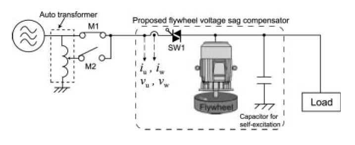
Figure 1 shows the system configuration of the volt- age sag compensator described in this paper. This is a commercial power supply system during normal operation in which the induction motor with a flywheel is connected in series to the load, and power is supplied to the load via a thyristor switch from the grid during normal operation. The actions during operation are as follows.
(1) Flywheel startup and standby operation
The induction motor starting current is suppressed and the induction motor is started up by phase control of the interconnection thyristor switch from the grid without a connection to a capacitor or load. During standby, the thyristor switch is in a conductive state at all angles, and the induction motor is in standby under virtually no load.
(2) Voltage sag occurs
When the grid voltage drops, an OFF signal is sent to SW1. When SW1 is OFF at the first current zero point after the voltage sag occurs, the induction motor automatically becomes an induction generator due to the capacitor self- excitation phenomenon, and power is supplied to the load. Because the frequency of the induction generator is lower than the grid frequency only for the “slip” portion, the load voltage vector rotates spatially at close to the slip frequency with respect to the grid voltage vector.
(3) Power restoration
When the grid voltage is restored and the voltage spatial phases on the grid side and the induction generator side (load side) agree (the voltage phase difference is zero), that is, when the voltage of the induction generator is rotated 360° in space and again matches the grid voltage, an ON signal is output to SW1. Reconnection in the state in which there is a voltage phase difference creates a disturbance in the grid and the interconnection switch faults due to the large current to the induction motor, and as a result, reconnection with the voltage phase difference near zero is always required. The process then returns to the standby state in step (1).
3.Simulated Voltage Sag Experiment (Power Source Voltage Drop Experiment)
In the experiment, we performed a simulated voltage sag test by switching an auto-transformer tap with an electromagnetic switch. Figure 1 shows the configuration of the test system.
3.1 Content of the voltage sag experiment and voltage sag determination
The flywheel system used in the voltage sag experiment was a system in which a 200-kJ flywheel was connected to an 11-kW-class squirrel-cage induction motor. Detection of the voltage drop involved calculating the three-phase instantaneous voltage by spatial vector computations, and monitoring the power flow to SW1 as well. A voltage sag was identified when the voltage shortfall detection threshold was 80% of the rated voltage (effective value: 160 V) and the power flow was reversed. The experimental conditions were set to a resistance load of 7.2 kW, and the self-excitation capacitor was set to 750 mF (reactive power: 9.3 kvar), which was optimal for 7.2 kW. A voltage drop width of 30% (residual current of 70%) was simulated.
3.2 Results of the voltage sag experiment
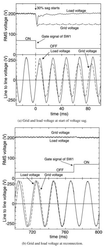
Figure 2(a) shows the results of the experiment. A voltage sag was detected at virtually the same time as the simulated voltage sag started. Because the interconnection switch is a thyristor, there is a period of approximately one-fourth of a cycle in which OFF cannot be set. We confirmed that during this period, the load voltage wave- form is chaotic, but thereafter the induction motor acts as an induction generator due to capacitor self-excitation, and a suitable voltage is generated. We then confirmed that because power is also restored in the same phase during power restoration [Fig. 2(b)], reconnection to the system is accomplished smoothly. The present voltage sag compensator does not use a semiconductor power converter to generate an AC voltage, and thus a sinusoidal voltage greater than 97% of the fundamental is generated without a filter even during compensation.
4.Design Guidelines for the Flywheel Stored Energy Capacity
There are two points to be taken into consideration when the frequency drops and reconnection is performed during compensation in the present voltage sag compensator as described above.
(1) Reconnection to the grid cannot be performed at an arbitrary period. After the start of compensation, standby is essential until the voltage phase difference from the grid side reaches zero again.
(2) In the present method, the induction generator is reconnected directly to the grid without a semiconductor power converter. As a result, even when the instant of zero voltage phase is reached, if the frequency drops too much, excess current due to excess acceleration torque flows during reconnection, and consequently a frequency lower limit (90 to 95%) must be set. The lower limit to the frequency drop during compensation is set while taking the above two points (voltage phase zero and frequency lower limit) into consideration. The flywheel stored energy capacity leading to the same phase when the lower limit of the frequency is reached is the optimal flywheel stored energy capacity for the present voltage sag compensator. Design guidelines are given in detail below.
4.1 Derivation of the phase matching time
When the load power to be protected is Pload, the mechanical power input to the induction machine from the flywheel is Pme. The mechanical energy ΔE that the fly- wheel releases in the compensation time t is
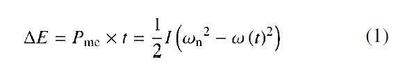
Here ωn, ω(t), and I represent the standby rotational angular velocity of the flywheel, the rotational angular velocity function after the start of compensation, and the inertial moment. The rotational angular velocity function ω(t) can be rewritten as
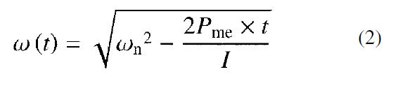
On the other hand, the relation between the frequency F(t) of the induction generator and the rotational angular velocity is represented by
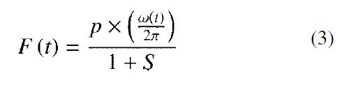
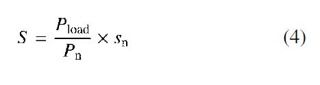
Here p is the number of pole pairs, S is the slip of the induction generator (although a negative value; S is a positive value due to inversion of the immediately preceding sign). With the slip at rated power denoted as sn and the rated power of the induction machine as Pn, we have
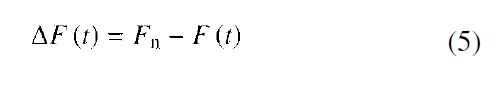
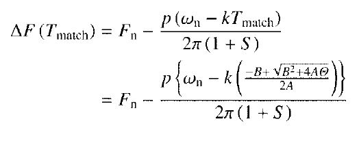
Therefore, if the rated frequency (grid frequency) is Fn, then the frequency difference ΔF(t) is
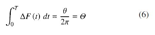
The time integral of this frequency difference is the phase angle θ, and the time t at which θ = 2π is the phase matching time Tmatch:
Here time integral (2), the rotational angular velocity function, is relatively complex. Further, Eq. (6) cannot be solved analytically in the form given. As a result, the rotational angular velocity function ω(t) is approximated linearly as
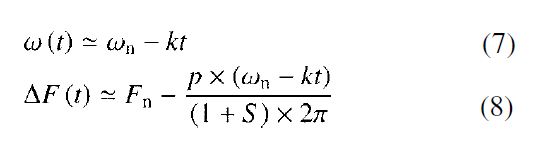
This is because when the compensation time is sufficiently small compared to the acceleration constant H = E/Pn for the rotating body, the drop in the rotational angular velocity is linear. Here k is a proportionality constant,
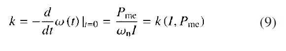
and is defined as the tangent slope of the rotational angular velocity function at t = 0. Hence, if Eq. (6) is rewritten using the voltage phase difference Θ of the grid side and the load side, the second-order constraint equation
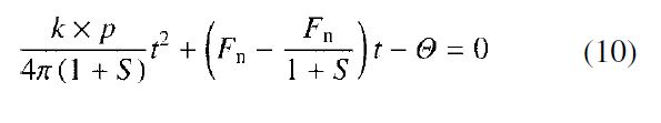
is obtained. Solving this equation, we obtain
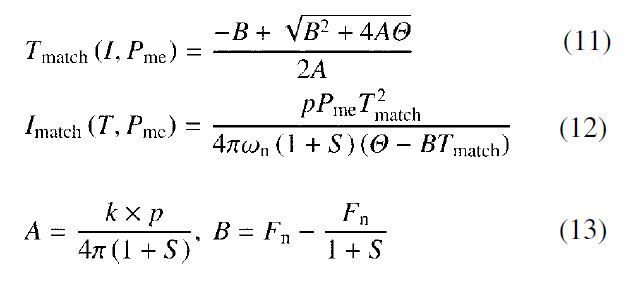
Thus, as shown in Eq. (11), after the start of compensation, the time Tmatch at which the voltage phase reaches zero again is θ = 2π, and is determined by the load power, the inertial moment, and the rated slip. Conversely, if the time Tmatch at which the same phase is reached is specified, then the required moment of inertia Imatch is determined by the time and load power, as shown in Eq. (12).
4.2 Flywheel design using the set frequency lower limit
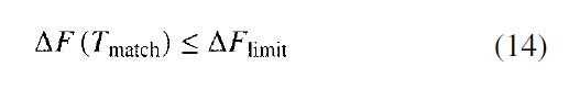
The lower limit of the frequency must be given closer consideration when designing a flywheel using the constraint equation in the previous section. That is, the frequency drop up to the time at which the voltage phase difference again reaches zero must be at least ΔFlimit. Then the constraint equation for the frequency drop is represented by
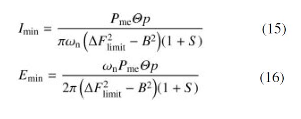
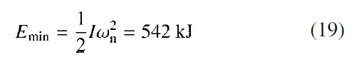
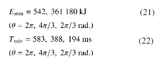
Solving this equation, we can express the necessary mini- mum inertial moment Imin and stored energy Emin by means of the following equations (see Appendix):
The time at which the same phase is reached for the stored energy Emin is
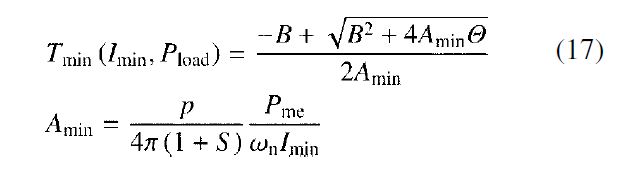
based on Eq. (11), which determines the minimum period of the compensation time.
4.3 Design of a 50-kW-class system for the voltage sag compensator
We designed a 50-kW-class system for the voltage sag compensator based on the calculations in the previous section. Table 1 gives the design conditions. Specifying a lower frequency limit 5% below the grid frequency (ΔF = 0.05), calculations were performed with the rated slip sn = 0.019 (based on a list of results for a prototype 55-kW-class induction motor) for the 55-kW-class induction motor with four poles at ωn = 1500 rpm. The necessary minimum moment of inertia to compensate a load at a load power of Pload = 55 kW (based on 92.5% efficiency of the induction machine, Pme = 59.5 kW) is found from Eqs. (15) and (17):
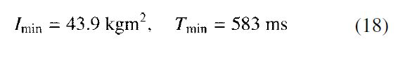
Therefore, based on Eq. (16), the necessary minimum stored energy is
If design is performed as described above, then the compensation time when compensating a constant load at Pload = 55 kW is 583 ms
4.4 Reduction of flywheel capacity due to an improved interconnection switch
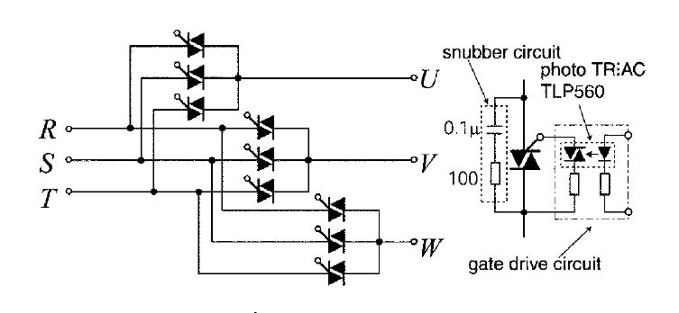
In order to restore power in the same phase when reconnecting to the grid as in the calculations in the preceding section, θ = 2π rad = 360° is assumed in Eq. (6). Thus, as shown in Fig. 3, if the interconnection switch is configured in a 9 TRIAC arrangement such as a matrix converter, then reconnection to the grid is possible in increments of θ = 2π/3 rad = 120°. In this case, the number of semiconductor switches increases, but as shown in Fig. 3, the TRIAC drive circuit has an extremely simple configuration with only a photocoupler and there is no need for an insulated power supply. Furthermore, because only three of the TRIACs have current passing through them at all times, the heat sink size (°C/W) and the constant loss in the switch do not change.
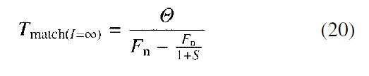
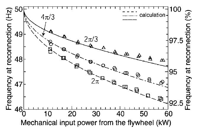
Based on this idea, Fig. 4 shows the relationship between the compensation time and the frequency difference for compensation of the rated power. The horizontal axis represents time, and the vertical axis represents the difference ΔF(t) between the grid frequency Fn and the induction generator frequency. First, if the moment of inertia of the flywheel is infinitely large, then the frequency difference is constant at Fn – Fn/(1 + S). In this case, the time to reach the same phase is I = ∞. As a result, rearranging Eq. (10) and setting k = 0, we obtain
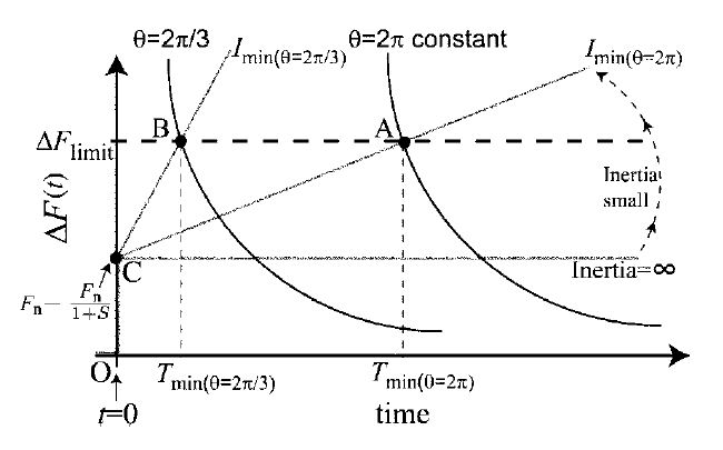
Next, when the moment of inertia is finite, the frequency difference ΔF(t) varies linearly with respect to time. If the frequency difference reaches a limit, then at the same time the moment of inertia at which the voltage phase difference changes to a constant curve with θ = 2π rad is Imin. That is, the area enclosed by the origin, point C, point A (point B when θ = 2π/3 rad), and Tmin is Θ = 1 (1/3 when θ = 2π/3 rad). The voltage phase differences q that can be selected depend on the number of phases: for three phases, there are three, namely, 2π, 4π/3, and 2π/3.
4.5 Flywheel guidelines based on an improved grid interconnection switch
Table 1. Design conditions of a 50-kW-class system
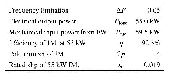
Using the improved grid interconnection switch de- scribed in the previous section, design was performed for the conditions listed in Table 1. The relationship between the compensation time and the stored energy when compensating rated power at 55 kW is shown in Fig. 5. If design is performed using region I (the dotted curve) in Fig. 5, then phase matching is reached at a given stored energy and the desired time, but the region is one in which the frequency drops below 95%. Conversely, if design is performed using region II (the dotted curve), the result is an overdesigned region in which there is still a margin for voltage drop when phase matching is reached in the desired time. Hence, the design point (optimal point) at which the frequency is 95% when phase matching is reached is the point at which the curves in Fig. 5 and the 5% frequency drop line intersect, so that
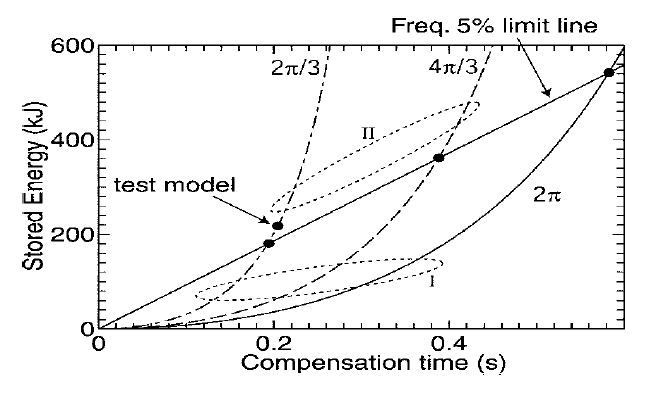
If the stored energy is greater than Emin, then the frequency drop is kept within 5% and reconnection to the grid is possible.
5.Experimental Evaluation of the Design Guidelines for a 50-kW-Class Test System
Based on the design guidelines in the previous section, we prototyped a 50-kW-class test system and con- firmed the validity of the design principles. The results are described below.
5.1 Specifications of the test system for the 50-kW-class voltage sag compensator
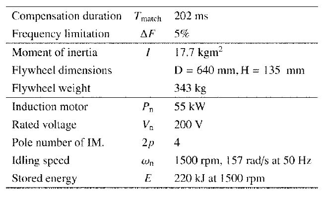
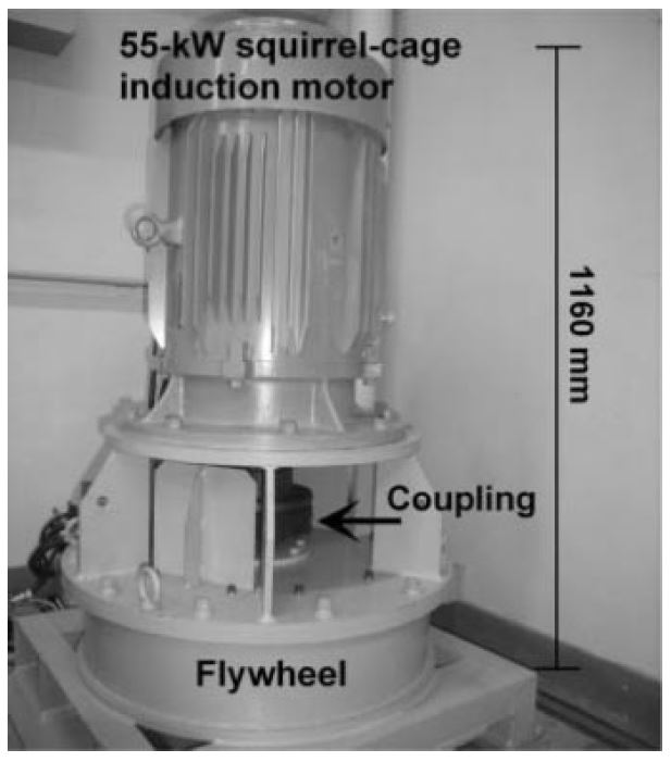
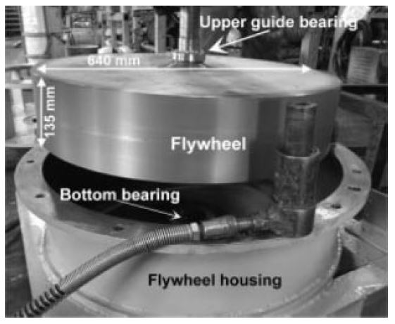
Because the majority of voltage sags are concentrated in the range of 100 to 200 ms [4], we created our test system using the test model point (reconnection to the grid at θ = 2π/3 rad) shown in Fig. 5. Table 2 lists the specifications for a 50-kW-class voltage sag compensator using the prototyped vertical-axis flywheel. Figures 6 and 7 show the external appearance.
Table 2. Test model specifications of the proposed 50-kW voltage sag compensator
5.2 Experiment to confirm the validity of the design guidelines
In order to confirm the validity of the design guide- lines for the proposed voltage sag compensator using the prototyped vertical-axis flywheel, we performed an experiment involving the opening of grid interconnection switch M1 rather than an experiment with a simulated voltage sag using the experimental configuration shown in Fig. 1. The capacitor value used for the self-excitation phenomenon was selected appropriately to the load [14], so that the induction generator produced approximately the rated volt- age Vn over a constant period during compensation. In practice, the load power often fluctuates, and countermeasures to automatically switch the capacitance as appropriate based on the fluctuations are extremely important. We performed our experiment by varying the compensation load from 10 kW to 55 kW. The total standby loss (iron loss, copper loss, wind loss, bearing loss) was approximately 1.77 kW.
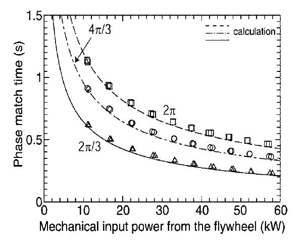
Figure 8 shows the experimentally determined matching time Tmatch for the same phase with respect to the mechanical input power Pme (the measured load power Pload divided by the efficiency of the motor with that load = the value for the mechanical load of the flywheel). For the voltage phase difference, the output q of the phase- locked loop (PLL) where the d axis voltage of the induction generator voltage is zero is calculated, and the times at which the voltage phase difference is 120°, 240°, and 360° are measured. As can be seen in the figure, the experimental results and the values calculated using Eq. (11) agree well. When the calculated value is taken as the true value, the error is positive (approximately +7% at most), and the time until the phase again matches is slightly longer.
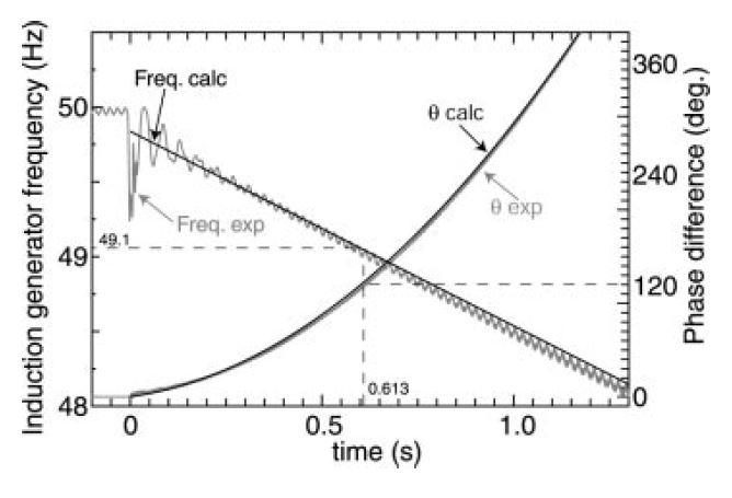
We also evaluated the induction generator frequency at phase match. Figure 9 shows the voltage phase difference and the frequency of the induction generator and the grid when the load power Pload is 10 kW. The frequency on the vertical axis was calculated from dθ/dt for the PLL. The figure confirms that the voltage phase difference expanded steadily from t = 0 s before compensation, and its time variation agreed well with the calculated values. The frequency dropped steadily, and at t = 0.613 s a voltage phase difference of 120° was obtained. The frequency at this time was 49.1 Hz. Figure 10 shows the voltage drop at phase match when varying the load power Pload as above. The experimental values for the voltage drop are more stable than the calculated values and the agreement is good. These results confirm the validity of the design guidelines in Section 4 for a system that compensates a 55-kW load for 0.22 second by reconnecting the test system to the grid at a voltage phase difference of 120°, using the grid interconnection switch in Fig. 3.
6.Conclusions
A flywheel stored energy of approximately 50 kJ is required for compensation of approximately 0.17 second when designing a 10-kW system (electrical output of 11 kW), as was the case in the previous section. If a two-pole system is used, then a voltage sag compensator with a simple horizontal axis can be created merely by having an approximately 65-kg flywheel overhang on the axis of the 11-kW-class squirrel-cage induction motor (horizontal axis). Thus, in this paper we proposed a simple voltage sag compensator using a flywheel to deal with the problem of voltage sag, and clarified the following three points.
(1) A voltage sag experiment simulating a 30% volt- age drop confirmed the effectiveness of the proposed method, which maintained approximately the rated load voltage even during reconnection immediately after the start of a voltage sag.
(2) We clarified flywheel design guidelines for our voltage sag compensator. We showed that a flywheel stored energy capacity of 180 kJ is optimal for a 50-kW system when the frequency drop during reconnection is 5%, and that the compensation time is approximately 0.20 second.
(3) We created a 50-kW-class test system (flywheel stored energy 220 kJ) based on the design guidelines. Experiments showed that the designed values and the experimental values agreed well, and demonstrated the validity of the design guidelines for a load power of 55 kW and an approximately 0.22-second compensation system.
REFERENCES
- Electric Technology Research Association. Countermeasures for instantaneous voltage sag. Electric Technol Res 1990;46(3).
- Niito T, Hayashi T. Current state and countermeasures for instantaneous voltage sag. Trans IEE Japan 2003;132:679–682.
- Sakamoto S, Abe M. Instantaneous voltage sag phenomenon. J IEE Japan 2008;128:598-601.
- Electric Technology Research Association. Current state and countermeasure technology for electric power quality in a distribution system. Electric Technol Res 2005;60(2).
- Committee on Technology for Industrial Power Electricity. Investigation into state of blackouts in factory electric equipment and trends in countermeasures. Tech Rep IEE Japan 2005;999.
- Matsuura T, Yoshino A. Countermeasures for instantaneous voltage sag. J IEE Japan 2008;128:603–605.
- Sakai Y. Device to compensate for instantaneous sag using an electric double layer capacitor. J IEE Japan 2008;128:610–613.
- Konishi Y. Device to compensate for instantaneous sag using a NAS battery. J IEE Japan 2008;128:606–609.
- Nagaya S, Hirano N, Shikimachi K. Device to compensate
for instantaneous sag using SMES. J IEE
Japan 2008;128:598–601. - Nielsen JG, Blaabjerg F. A detailed comparison of system topologies for dynamic voltage restorers. IEEE Trans IA 2005;41:1272–1280.
- Kato S, Cheng M, Sumitani H, Shimada R. Semiconductor power converterless voltage sag compensator and UPS using a flywheel induction motor and an engine generator. PCC-Nagoya 2007, p 1680–1685.
- Kato S, Takaku T, Sumitani H, Shimada R. Development of voltage sag compensator and UPS using a flywheel induction motor and an engine generator. IEE Japan Trans IA 2007;127-D:844–850. (in Japanese)
- Murthy SS, Malik OP, Tandon AK. Analysis of selfexcited induction generators. IEE Proc-C Gener 1982;129:260–265.
- Chan TF. Analysis of self-excited induction generators using an iterative method. IEEE Trans Energy Conversion 1995;10:502–507.
APPENDIX
Derivation of Eq. (15)
On the left side of Eq. (14), the conditional equation for the frequency drop during reconnection can be converted to
by using Eqs. (8) and (11). Because pωn = 2πFn, the same equation can be represented as
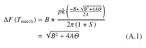
using Eq. (13). Therefore, the inequality in Eq. (14) can be altered to
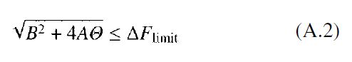
Because both sides of the inequalities are positive, the direction of the inequality sign does not change if both sides are squared. If Eq. (A.2) is rearranged by using Eq. (13) after squaring both sides, we obtain
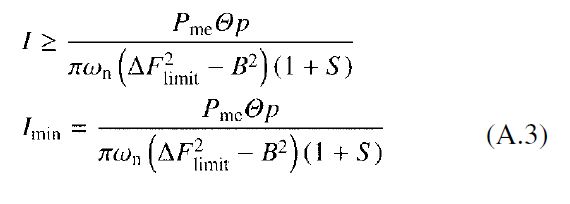
which yields Eq. (15).
AUTHORS (from left to right)
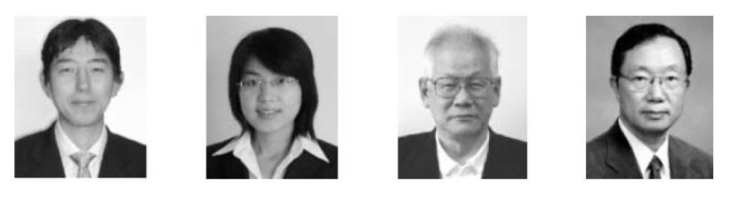
Shuhei Kato (member) completed the doctoral program in innovative energy at the Graduate School of Science and Engineering of Tokyo Institute of Technology in 2009. He is now engaged in research on energy storage using flywheels. He received a 2007 Institute of Electrical Engineers of Japan Excellent Presentation Award. He holds a D.Eng. degree.
Miao-miao Cheng (member) completed the M.E. program at Xi’an Jiaotong University in 2006 and entered the doctoral program in innovative energy at the Graduate School of Science and Engineering of Tokyo Institute of Technology. She is now engaged in research on flywheel energy storage for stabilizing distributed power source transients.
Hideo Sumitani (senior member) received a bachelor’s degree from the Department of Electrical Engineering of Tokyo Institute of Technology in 1959 and joined Toshiba, where he was engaged in the development, design, and production of AC electric motors for industry. In 1991 he joined Toshiba Techno Consulting. In 1998 he joined Tokyo Power Technical Services. In 2001 he joined Toshiba Technical Services International, and became a researcher at the Atomic Reactor Engineering Laboratory of Tokyo Institute of Technology, where he is also a visiting instructor.
Ryuichi Shimada (senior member) completed the doctoral program at the Graduate School of Tokyo Institute of Technology in 1975 and joined the Japan Atomic Energy Research Institute, where he worked on the development of the large-scale Tokamak JT-60 fusion reactor. In 1988 he became an associate professor in the Department of Electrical and Electronic Engineering in the Faculty of Engineering of Tokyo Institute of Technology. He was appointed a professor at the Atomic Reactor Engineering Laboratory there in 1990. In 2005 he became a professor at the Integrated Research Institute. He is primarily engaged in research on large-scale electric power systems, electric power engineering, electric power storage, power electronics, nuclear fusion reactor engineering, and plasma control. He has received the IEEJ Outstanding Paper Prize, Progress Prize, and Authorship Prize. He holds a D.Eng. degree.
Electrical Engineering in Japan, Vol. 181, No. 1, 2012
Translated from Denki Gakkai Ronbunshi, Vol. 129-D, No. 4, April 2011, pp. 446–452
