Published by Electrotek Concepts, Inc., PQSoft Case Study: Power Factor Correction and Harmonic Control for dc Drive Loads, Document ID: PQS0410, Date: December 31, 2004.
Abstract: This case history describes the design of power factor correction and harmonic control equipment for loads at a plastic film manufacturing plant. Measurements were performed to characterize the harmonic generation and power factor requirements of the load. The electric utility supplying the new facility is requiring that the plant meet the harmonic current limits specified in IEEE Std. 519-1992
Harmonic filters that can meet the IEEE Std. 519 guidelines for the specific load characteristics were designed. General filter design guidelines for this type of application are presented.
INTRODUCTION
DC drives can be a significant percentage of plant load in many industrial facilities. They are commonly used in the plastics, rubber, paper, textile, printing, oil, chemical, metal, and mining industries. These drives are still the most common type of motor speed control for applications requiring very fine control over wide speed ranges with high torques.
Power factor correction is particularly important for dc drives because phasing back of the SCRs results in relatively poor power factor, especially when the motor is at reduced speeds. Additional transformer capacity is required to handle the poor power factor conditions (and the harmonics) and more utilities are charging a power factor penalty that can significantly impact the total bill for the facility.

SYSTEM DESCRIPTION
The customer manufactures heavy-duty plastic film. The process uses calenders that are driven by dc motor drives. As a result, there is significant harmonic current generation and the plant power factor without compensation is quite low. Shunt capacitors can be added to partially correct the power factor but this can cause harmonic problems due to resonance conditions and transient problems during capacitor switching by the utility.
The customer is planning to build a new facility that will include two calender lines similar to lines at their existing facility. Measurements performed at the existing facility are used to characterize these dc drive loads and additional analysis is described to determine power factor correction and filtering requirements for the new facility.
The customer would like to correct the power factor to 0.95 with power factor correction equipment (capacitors). However, the power factor correction must take into account the potential for resonance that could magnify the harmonic currents generated by the dc drive loads. This usually means that harmonic filters are required. In addition, the electric utility supplying the new facility has required that the customer meet the limits in IEEE 519-1992. This results in a need for harmonic filters to reduce the harmonic current components injected onto the utility system.
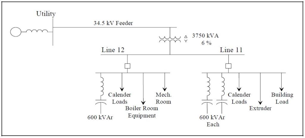
The plant electrical system consists of two sets of 480 volt switchgear fed from a common 480 volt bus. A 3750 kVA transformer steps down from a 34.5 kV distribution line for the entire facility. Figure 2 shows a oneline diagram of the facility.
POWER FACTOR CORRECTION REQUIREMENTS
The calender lines at the new facility will be similar to existing lines at the existing facility. Therefore, measurements at the existing facility are used to estimate the power factor correction that will be needed at the new facility. Since all of the load will essentially be connected to the same 480 volt bus at the new facility, the important consideration is the total power factor for the two switchgear lines.
Measurement Results
Measurements were performed characterizing typical calender line conditions at the existing facility. There were two very important findings from these measurements:
- Displacement power factor for the calender line loads (almost exclusively dc drives) ranged from 0.65-0.70. This displacement power factor determines the capacitor/filter sizes required for the loads.
- There is significant cancellation of harmonic currents resulting from the different dc drives fed from the main bus. Whereas the total harmonic distortion in the current for a single drive is approximately 30% (see Figure 1), the total harmonic distortion for the total current at the bus was usually on the order of 15%, not including the effect of resonances caused by capacitor banks. This is an important consideration when determining the filter rating requirements and the ability to meet IEEE 519 harmonic current limits.
Power Factor Calculations for the New Facility
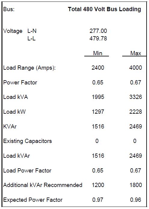
The power factor requirements for the new facility are calculated based on the total expected load. Table 1 shows the calculation of the power factor correction requirements at estimated minimum and maximum load levels. The estimated power factor of the loads is based on the measurement results. Based on these estimates of plant loading, a total compensation of 1800 kVAr should be sufficient to maintain a power factor exceeding 0.95 for all load conditions.
Table 1 – Calculation of Power Factor Correction for Total Plant Loading
ANALYSIS OF HARMONIC DISTORTION CONCERNS
For the purposes of harmonic analysis, the dc drive loads can be represented as sources of harmonic currents. The system looks stiff to these loads and the current waveform illustrated in Figure 1 is relatively independent of the voltage distortion at the drive location. This assumption of a harmonic current source permits the system response characteristics to be evaluated separately from the dc drive characteristics. The representation of the drives as harmonic current sources is shown in Figure 3.
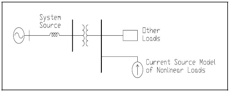
Analysis of the system response is important because the system impedance vs. frequency characteristics determine the voltage distortion that will result from the dc drive harmonic currents. A simplified version of the situation is shown in Figure 4.

If the system is infinitely strong (no impedance), there will never be any voltage distortion. It is the harmonic currents generated by the dc drives passing through the system impedance that causes voltage distortion. Filters are the means used to control the system response.
Harmonic Distortion Levels at the Existing Facility
Initial power factor correction procedures for the existing facility involved installation of capacitor banks for each calender line. One or two 600 kVAr banks were used for each line. This resulted in problems with high voltage distortion levels in the plant and also caused transient voltage magnification when the utility company switched a higher voltage transmission system capacitor bank. To prevent these problems, the 600 kVAr capacitor banks are being configured as harmonic filters rather than just capacitors. The configuration is shown in Figure 5.

The filter is tuned below the fifth harmonic. This limits the additional harmonic current that must be absorbed from the utility system and also allows for tolerances in the filter components.
The addition of a single 600 kVAr filter significantly improved voltage distortion levels at the 480 Volt bus. Figure 6 compares the voltage harmonic spectrum with and without the filter in service.

Filter Design for the New Facility
The switchgear lineups at the new facility are being configured with 1200 Amp switchgear. For this reason, the individual power factor correction steps are being limited to 600 kVAr. Based on the power factor correction estimates, two steps will be installed initially and a third step will be added in the future if it is warranted based on actual plant loading.
Each 600 kVAr step will be configured as a harmonic filter tuned to approximately 4.7 times the fundamental frequency (60 Hz). 600 volt capacitors will be used for these filters to prevent overloading due to voltage rise across the reactor and harmonics from the power system. In order to accomplish this, capacitors with a nominal rating of 900 kVAr at 600 Volts will be required. Figure 7 provides the specifications for the recommended filter configuration. The specifications are based on two filters sharing the maximum load at the new plant.

Evaluation of Current Limits in IEEE 519
The IEEE 519-1992, “Recommended Practice for Harmonic Control in Electric Power Systems”, provides recommended harmonic current limits for individual customers at the point of common coupling with the electric utility. The utility supplying the new facility has specified these harmonic current limits in the contract with the customer. Therefore, it is important to make sure that the specified harmonic filters will adequately limit the harmonic currents injected onto the utility system.
A few assumptions are required to make this evaluation. A short circuit capacity at the transformer high side of 23 MVA is assumed. This is relatively low because the plant is supplied from a long 34.5 kV feeder circuit. Worst case harmonic generation levels are assumed which do not include significant cancellation from the different drives. The IEEE 519 evaluation is based on an “average maximum demand current” defined as the average of the monthly maximum demand values for twelve months. For a new plant this must be estimated. 3000 kVA was used for this evaluation.
Figure 8 evaluates the expected current distortion levels with respect to the IEEE 519 limits for the case without compensation or harmonic filters. The limits are exceeded at almost every individual harmonic frequency and for the total demand distortion (TDD).

Figure 9 illustrates the effect of the proposed 600 kVAr filters on the expected harmonic current levels being injected onto the utility system. These values were obtained from a simulation of the system response. The limits are not exceeded at any individual frequency or for the total demand distortion. There should be no problem with the IEEE 519 limits for the proposed filter configuration.

SUMMARY
DC Drive loads can have a low displacement power factor, resulting in a need for power factor correction. The power factor correction can be sized based on the displacement power factor of the load but all of the compensation should be installed as harmonic filters to avoid harmonic resonance problems and excessive voltage distortion levels. Filters tuned below the fifth harmonic will usually be adequate to keep voltage distortion levels below 5% and current harmonics injected onto the utility system below the levels specified in IEEE 519.
REFERENCES
T.E. Grebe, M.F. McGranaghan, and M. Samotyj, “Solving Harmonic Problems in Industrial Plants and Harmonic Mitigation Techniques for Adjustable Speed Drives,” Electrotech 92 Proceedings, Montreal, June 14-18, 1992.
T. Grebe, “Why Power Factor Correction Capacitors May Upset Adjustable Speed Drives,” Power Quality, May/June, 1991.
M.F. McGranaghan, R.M. Zavadil, G. Hensley, T. Singh, M. Samotyj, “Impact of Utility Switched Capacitors on Customer Systems – Magnification at Low Voltage Capacitors,” Presented at the 1991 IEEE T&D Show, Dallas, TX, September, 1991.
GLOSSARY AND ACRONYMS
PCC: Point of Common Coupling
SCR: Short Circuit Ratio
TDD: Total Demand Distortion
THD: Total Harmonic Distort
