Published By M.L.Sachdeva, Former Chief Engineer, CEA & N.S.Sodha, Former Executive Director, PowerGrid. Conference on ‘Reliable & Quality Power’ on 30-31st May 2019 CBIP Conference Hall, New Delhi.
Synopsis
Reactive power compensation technologies inhibited in the Distribution system as also Power system of the Present (Conventional) and Power System of Future (Up-front Conventional cum Renewable Resources system) and that predominately Renewal Generation system Globally by 2050 (about 64%) and changes in the compensation devices attributed to power electronic controls , HVDC deployment of Voltage source converter using IGBT/IEGT or IGCT needing no reactive power, digital technologies based equipment, digital devices for communication, data storage & transfer, Micro grid & Smart city conceptualization, Smart meters, intelligent controls in distribution network, software internet remote controlled devices, security from cyberattack, etc. are highlighted
International and National Studies made on contribution of reactive power by Solar generators/panels/ Projects as also techno-economic comparison of nos. of operation of transformer tap changer vs solar converter/ inverter operation, etc. are also briefly highlighted.
As fossil fuel synchronous generators are being laid off to control emission of greenhouse gases & their adverse effect on power system stability, the reactive power day time and night time contribution of Utility Solar Voltaic Mega Farms / Roof top Solar Panels & Community Solar Project Smart PV Converters /inverters of standard rating and over load rating need consideration while making estimation of total reactive power requirement as also its management during operation.
In addition to attributes of solar inverters to supply reactive power during day time leading to reduction in its active power output and consumption of power from grid during night time operation, it is opined that its weightage on the tariff fixation for supply of active and reactive power during day time and drawing of grid/ ancillary source power for inverter functioning for supplying reactive power during night also needs be considered.
Key words: Reactive power compensation, HVDC, Voltage Source Converter IGBT/IEGT or IGCT, Solar Mega Solar & Wind Farms, Community & Roof Top solar Voltaic Panels , Wind turbines, Power converter/ inverter capability of reactive power compensation, Day Time and night time solar tariff, DSTATCOM, Digital Data communication, smart meters, digital devices, EV transportation, Batteries.
1. Introduction
Thrust on mitigation of harmful effect of Greenhouse gases attributed primarily to fossil fuel power generation and ensuring compliance to the Global Agreement on Climate Change limiting temperature rise to 2°C (preferably 1 ½°C) on Earth Planet, the Renewables growing through the development of utility scale solar photovoltaic farms and wind farms, as well as Distributed Energy Resources (RES) are a complete change paradigm. These fast changes including EV transportation with battery storage facilities to supply power to grid during peak power requirement(V-t-G), etc. and all these changes have brought out a need of reactive compensation throughout the power system. These aspects are briefly detailed as under:
1.1 Power System of the Present
The conventional power system is one-way power flow system and comprises of remotely located self-regulated power generating stations within their design & operation limits, associated transmission system (HVDC /EHVac) including first stage reactive power compensation followed by distribution system coupled with fixed / switchable shunt reactive compensation to cater to the consumers’ loads (active &reactive) at HV /LV levels. Renewables (Solar Voltaic & Wind Farms) are the recent entrant.
In the transmission system, the additional reactance requirement met by compensation devices (switched / non switched/ variable shunt reactive compensator) as also adoption of HVDC (current commutated thyristor valve & associated system requiring reactive power consumption) & FACT power electronic devices as also series compensation (insulated platform supported) on long TLs for increasing their power carrying capacity.
Distributed system for distribution of power at HV/LV to load centres/ consumers are reactive compensated by providing distribution transformers with off-load / On-load tap changer, shunt reactive compensation (fixed / switched) in the distribution system / at the Load centres and DSTATCOM with industrial Arc furnaces to regulate reactive power requirement to maintain system voltage & power factor and control harmonics generated in the industrial process.
The real time operation in the ‘generation and transmission system’ are achieved thru SCADA/ SAS, EMS, Generation Scheduling & Dispatching, System Load Flow study, System Stability, etc. and in ‘distribution system’ thru SCADA, RMU and auto reclosures in the urban distribution system and pole mounted Sectionalizers with fuses and with / without isolators to roaster Loads and isolate the faulty section.
Post real-time operation, SCADA/SAS routinely records all system data including voltages, active and reactive power flows, generator outputs, demand, frequency and tie-line flows and control operation under normal / abnormal operational conditions. Analysis of abnormal system operational conditions and system disturbances heavily relies on accurate time-tagged ‘System disturbance recorder and Fault recorder’ data collected by such devices. In certain cases where equipment damage has occurred, other data such as climatic data, metallurgical and other forensic data such as oil and gas samples often become necessary.
1.2 Power System of the Future
Over 50-year of equilibrium (60 t0 70% contribution by fossil fuel power generation) is coming to an end as Renewable Energy and Batteries fundamentally are re-making electricity systems around the world. As coal-fired generation units retired, initially substituted mostly by natural gas, but now with renewable additions, especially Utility scale solar & wind and distributed energy resources, are already dominating in most countries. This share of global renewable is expected to grow to about 64% by 2050.
Renewables growing through the development of utility scale solar photovoltaic farms and wind farms, as well as distributed resources in most of developed countries are connected to distribution system / load centres. The distribution system now works two-way power flow. Countries like India with scattered Renewable Mega Farms over regions of high irradiance are connected to main grid over HVDC/ EHV transmission system to bring to the distant load centres. However, roof top and community solar system, subsequent to meeting the individual / community local consumption, are also connected to HV / LV distribution system. System in both the cases experience power flow fluctuation due to variable renewable/ variable loads and as such need to provide reactive compensation thru Variable Shunt Reactors (VSR) not needing very fast and dynamic response and power converter (power switches built up of Power semiconductors) and these power switches control the output power both active and reactive.
A number of new grid users in the form of devices connected to the system is growing exponentially and new digital grid technologies and equipment are available. Distribution and /or Transmission utilities need to be enablers for the connection of new grid users and drive the implementation of this technology. Digital tools that enable seamless integration of grid layers and edge devices take an active role in supporting grid operations as also making a head away in the technology of future system and afford higher degree of interoperability. Digital technology also supports asset performance management and field maintenance players. The next generation of maintenance crews are growing up with Tablets and Smart Phones and Virtual Reality and expect to have these technologies supporting their work.
HVDC system now deploy voltage source converter using IGBT/IEGT or IGCT components needing no reactive power consumption and voltage source converter can operate at unity power factor and even as reactive power generator and examples of such devices are STATCOM, SSSC, UPFC, etc.
The operational facilities provided in the Power System of Present mentioned under Para 1.1 is now inhibited with Power electronics-based devices enabling better utilization to be achieved of all the principal attributes of the electric network.
At a component level, increasing reliability of digital processors has led to almost complete dominance of such devices over the conventional analogue-type control systems. Increasingly, the digital control systems are also being installed for protection, indications, measurements, monitoring and control purposes. Furthermore, these devices are being integrated to perform these functions in a single control unit (SAS)utilizing the same system quantities. While this has the promise of savings in terms of installed equipment, it requires application of special measures (BCU, Ethernet switches, Network controller, Disturbance Recorder, etc.) but it achieves higher reliability, security, safety, operation ability and fast mode of analysis.
Fibre optic-based communication technologies have facilitated increasing use of digital control systems as well as increased functional integration of protection, indications, measurements, monitoring and control. With the rapid development of computing and communication systems, micro grid and smart city initiatives have been developed at a great pace. These initiatives focus on consumer demand control, remote switching and smart metering along with adequately defined objectives as well as protocols and standards including safety standards.
Increasing use of Internet-based communications also exposes transmission and distribution utilities to malicious attacks and hacking activity. These issues are likely to require increasing efforts to ensure robustness of systems to such threats. Inverters getting popularize in the power system with remote operation thru internet are exposing the system to cyberattack. They communicate with the supply grid to perform voltage management function autonomously using internet connected software.
2. Management of Reactive Compensation
Types of sources of Reactive Power (Fig.1) are Dynamic (Synchronous generators, Synchronous condensers & Solid-State Devices (power electronic converter and devices as FACTs – SVC) and Static Reactive Power Sources (Capacitive & inductive compensators, under- ground cables & O/H TL) and PV system (Photo Voltaic inject active power and reactive power component)
Reactive Power Sinks are Induction motors, Transformers, under excited synchronous machines, Heavily loaded transmission lines.

Today’s power system is primarily managed by evaluating the load including EVs and then matching the dispatching generation (Conventional & Renewables) to meet peak demand. Overtime shift in this traditional thinking is tending into a great change to see more aggressive shaping of consumer load to match renewable generation characteristics thru Demand management of industrial consumers as well as smaller consumers. The power utilities have introduced time-of-use tariff for shifting peak loads to non-peak hours by making the customers to be incentivized to use timers that could run their high-power demand implements when there is surplus solar power.
The introduction of Renewables / DER has introduced a new method of reactive compensation thru use of power inverter in addition to use of other reactive compensators viz. distribution FACT devices (D STATCOM), Shunt compensation on feeders/ loads, etc.
2.1 Reactive Contribution Control by Solar Voltaic Panels (Ref 2)
The Solar Voltaic Energy plant comprises of Mano / Poly Crystalline silicon Panel strings connected in series and / or parallel to connect the requisite power(KW/MW) thru dc current and dc voltage( 1000V to 1500V max) combination, combiners for interconnect panels output, power inverters /module-level power electronics (MLPEs) (Solar Edge, En-Phase , SMA, Tigo Energy, ABB) for conversion dc to ac , copper wires for interconnection of cells / panels, step up power transformer of voltage rating upto 33kV for connecting to nearest ac substation
Latest version of Inverters viz Smart inverters are a more sophisticated version of power electronics that can make autonomous decisions to keep the grid stable and reliable as more distributed energy resources come online. Smart inverters capable of having two-way communication and with its advanced software also perform specific grid-supportive functionalities related to voltage, frequency, communications and controls (New IEEE 1547TM-2018 Standard for Distributed Energy Resources)
To avoid harmful voltage fluctuations to the grid due to solar power, smart inverters can ride-through small disturbances (for example, voltage changes), meaning they can switch into standby mode and observe how long the disturbance takes place, then turn off only if the disturbance lasts too long.
2.2 Power Inverters Capability to Supply Reactive Power (Ref 2 &3)
2.2.1 Wind Farms
Fig 3 & 4 describes wind farms using asynchronous generators, the plant requirement of reactive power is met thru Energy storage with power converter (inverter in current mode using current-regulated pulse-width modulation) as also deployment of SVC/ SVC in parallel with fixed capacitor when the wind changes and stabilize the function of Wind Farm.


2.2.2 Solar Voltaic Farms
The details capability ofthe inverter -coupled generators viz. Solar PV Panels to provide reactive power limited to maximum current of power electronic elements is discussed. As long as absolute value of current does not exceed the limit, the phase angle of current vector can be arbitrarily controlled (Fig 4). It is possible to control active and reactive currents independently from each other. (Ref 4)
Characteristic of Power Inverter (Ref 5)
Fig. 5 shows the current domain for a constant reference voltage. It displays the circle of the maximum rated current I (max.R) and the maximum overload current I (max.OL). The overload capabilities of a PV inverter are unequally distributed as the connected DC source viz. PV module does not allow overload flexibility thereby limiting the maximum active current Ipmax. The active current of the PV inverter is determined by the solar irradiation. Within these limitations, the reactive current of the PV inverter can be controlled arbitrarily with response times in the order of milliseconds.
The maximum apparent power capacity S max of a PV inverter consist of active and reactive power components similar to conventional power. The active power generation Ppv can be assumed to be the most valuable so that it is considered to be the second restriction of the maximal possible reactive power supply
Q max (t) = Sq root [ S²max− P²pv(t)]
Depending on the utilization of active power of the PV inverter, the reactive power supply can be made use of.
Study also make comparison of reactive power contributed by power converter of standard rating and over rated inverter and the same is shown in Table 1 of a 110KWp Solar Panel deployed in Kassel, Germany, 2005. Table gives performance data analyzed with mean values of 15minutes of 100KVA PV Inverter which connects a 110KWp PV Panel and oversized 110KVA inverter. It may be observed with 10KVA oversized, addl. 20KVAr is available over 99.9%.
The Table also indicates that it is not possible to guarantee 100% reactive power supply (available more than 99.9%) without oversizing the inverter.

Reactive Power Requirement (Blue)
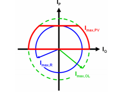
ImaxPV: current domain of PV Inverter (Red)
ImaxR: Rated current domain of bidirectional Inverter (Blue)
ImaxOL: Over load current domain of bidirectional Inverter (green)
Table.1 Available Reactive Power of a 110KWp Solar Panel in Kassel, Germany in 2005

Cost of Reactive Power Supply by PV Inverters (Capital-standard & over rated, Operational) (Ref 5)
Standard PV inverters do not make use of reactive power supply function as the owners of PV generators often do not get incentives for providing reactive power supply. Before analyzing the benefits, the cost of this functionality (investment cost & operational cost) is briefly discussed hereunder:
Additional investment cost
The provision of reactive power might require changes of the inverter’s topology or its dimensioning for an optimized layout using this new functionality. The option of oversizing the inverter is not considered because 100% availability is not a must and significant additional cost on this account is avoidable. The available reactive power potential should be used as a starting point with as low costs as possible. Study carried out in Germany revealed that without reactive power, full load hours of 900 h/a are achieved in average. However, additional reactive power supply may increase the loading of the inverter. This additional loading might reduce negligibly the life time of the DC link capacitors of single or three phase inverters. Considering 20years life, Three-phase inverters have by far smaller DC link capacitors which results in even smaller additional costs than for single phase inverters. For these reasons this study neglects additional investment costs.
Additional investment costs have to be considered if the inverter’s rated capacity is extended for higher capabilities and availabilities of reactive power supply. This will increase the total additional costs for reactive power supply.
Additional operational costs
PV generators have low operational costs as little maintenance is required in normal circumstances and no fuel costs occur except for self-power consumption of inverter as addl. losses. This cost component needs to be analyzed on the assumption that the inverter has no external power supply for self-consumption and is installed at the point of common coupling without additional losses by wiring.
Additional costs during Daytime and Nighttime
These costs are considered separately for estimating the additional costs of reactive power supply:
- During Daytime the inverter feeds active power that is generated by the PV modules into the grid. The additional losses accompanying the reactive power supply reduce this active power injection. Hence, the costs of the additional losses are the opportunity costs due to reduced active power supply.
- During Nighttime the PV modules do not provide any active power. The inverter losses due to reactive power supply are then compensated by the external grid (here: mains) resulting in costs due to the tariff of active power purchase.
This distinction is necessary as long as there are differences of the value of active power supply and purchase.
For further study, Ref at S.No 5 may be perused.
2.3 Adaptive Reactive Power Injection by Solar PV Inverter to Minimize Tap Changes and Line Losses (Ref.6)
Study performed on reactive contribution of Solar PV Inverter as per SLD of Simulated System (Fig.6) for reactive compensation in the associated supply network and its effect on number of the OLTC tap changing operation states as follow:
- There exists a compromise between minimization changes and line losses.
- Table 2 reproduced below from the Study summarizes for various power input due to variation of solar irradiations from a Solar system connected to the network operating at unity power factor and cases making controlled reactive power supported thru PV inverter.

Table.2 Effect of Ks on Number of Tap Change Operation and Reactive Energy
| Simulation Conditions | Value of Ks (W/min) | Nos of Tap Changes | Reactive Energy (MVAr-s) |
|---|---|---|---|
| Without Reactive Power Injection | – | 26 | 0 |
| With Proposed Scheme | -14 | 4 | 1.324 |
| With Proposed Scheme | -70 | 6 | 0.6 |
| With Proposed Scheme | -130 | 12 | 0.46 |
The study recommends to make techno economic comparison of life of tap changer and its cost vs cost of PV inverter for supplying reactive power.
2.4 California ISO: Reactive Power Requirements and Financial Compensation -Issue Paper (Ref 7)
The Issue Paper summarized California ISO initiative on uniform requirement for asynchronous resources (Wind, Solar, Battery, etc.) to provide reactive power capability and voltage regulation as also a mechanism to compensate units for reactive power capability and provision. The study by ISO showed that asynchronous renewable resources has resulted in high ratios of asynchronous to synchronous generation during a portion of the operating day. As nos. of synchronous (Fossil fuel gen stns.) generation is decreasing, ISO are making a precondition for asynchronous renewables resources to provide reactive power capability as a condition of interconnecting.
2.2.4 GETCO in their paper on ‘Challenges in Integration of Renewal Energy to Grid – A Holistic Approach by Improving Technical Requirements as well as Promotion of New Technologies for Grid Stability and Reliability’ ( Ref 8) has discussed making use of reactive compensation during daytime available from Power converter/ rectifier considering reduction in Active power during this processer while making system studies including stability but reactive power contribution of solar plant during night time and operating power consumption from grid and its effect on tariff is also required to be considered.
2.4.5 While planning reactive compensation, it is presumed GOI/ State System Planners also carry out techno-economic study to ascertain the use of capability of Power Inverters (normal rating and over capacity say 20%) to supply reactive power to transmission / distribution network during day & night as the cost of renewable falling down vis-à-vis conventional sources of reactive compensation and offer reasonable incentives to operators of PV generators for providing a benefit for the network operators by using their reactive power control capabilities. The utility specification also needs to specify reactive power contribution of solar plant in addition to active power and seek techno economic evaluation with and without reactive power consideration during bid making
3. Conclusion
i) Power System of the Present and of the Future highlights the new entrants/ modernization of power system -Renewables & Conventional operating in synchronous , improvement in HVDC thru voltage source converters GTO or IGBT/IEGT or IGCT, digitization thru digital tools enabling seamless integration of grid layers and edge devices enabling new technologies and players to take an active role in supporting electric system operations as also making a head away in the technology of future system and afford higher degree of interoperability, next generation of maintenance crews are growing up with Tablets and Smart Phones and Virtual Reality.
ii) Capabilities and availabilities of reactive power supply of PV inverters offer an interesting potential and its economic usability in network management as also reduction of network losses and congestions needs evaluation.
iii) Inverters getting popularizes in the electric system with remote operation thru internet are exposing the system to cyberattack. They communicate with the supply grid to perform voltage management function autonomously using internet connected software. This tends to be more critical involving a large aggregation of smart inverters and moving their voltages simultaneously in the wrong direction, it could cause the supply system to collapse.
iv) With the fast upcoming of Renewable in India, it is presumed GOI/ State System Planners carry out techno-economic studies to ascertain the use of capability of Power Inverters (normal rating and over capacity say 20%) to supply reactive power to transmission / distribution network during day & night as the cost of renewable getting comparatively cheaper vis-à-vis conventional sources of reactive compensation and offer reasonable incentives to operators of PV generators for providing a benefit for the network operators by using their reactive power control capabilities.
References
1. EL-PRO-CUS (Electronic Projects Focus): The Importance of Reactive Power in Power System Network.
2. ABB White Paper:Modernizing the grid to stabilize the integration of renewable energy gtm 26th April 2019)
2(a). E.Muljadi and et-al NREL,Golden Colorado 80401 : ‘Energy Storage and Reactive Power Compensator in a Large Wind Farm’ US Government Contract No DE-AC36-99GO 10337 / 34701 Wind Parks -Reactive Compensation
3. Xu Chen Thesis dated 6th Jan 2012, Worcester Polytechnic Institute —-: Reactive Power Compensation and Energy Storage in Wind Power Plant)
4. Andey Leon: ’Reactive Power Compensation for Solar Power Plants’ , IEEE PES Chicago Chapter , 12th Dec 2018
5. M. Braun Institut fuer Solare Energieversorgungstechnik Germany: ‘REACTIVE POWER SUPPLIED BY PV INVERTERS – COST-BENEFIT-ANALYSIS’, 22nd European Photovoltaic Solar Energy Conference and Exhibition, 3 – 7 September 2007, Milan, Italy)
6. Anubrata Das et-al Deptt of Elect Engg , IIT Kanpur : ‘Adaptive Reactive Power Injection by Solar PV Inverter to Minimize Tap Changes and Line Losses’ partly on behalf of MOP & DST,GOI 978-1-4799-5141-3/14/531.00 @ 2016IEE
7. California ISO: Reactive Power Requirements and Financial Compensation -Issue Paper 22nd May 2015
8. BB Chauhan et-all GETCO: ‘Challenges in Integration of Renewal Energy to Grid – A Holistic Approach by Improving Technical Requirements as well as Promotion of New Technologies for Grid Stability and Reliability’ GRIDTECH March 2019
