Published by Mirus International Inc., [2010-01-08] MIRUS-FAQ001-B2, FAQ’s Harmonic Mitigating Transformers, 31 Sun Pac Blvd., Brampton, Ontario, Canada. L6S 5P6.

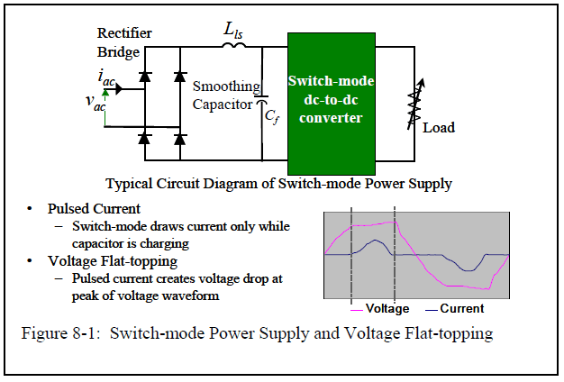
The switch-mode power supply (SMPS), used in most digital electronic equipment, is an excellent example of a non-linear load. Because it draws current in non-sinusoidal pulses, the SMPS is a significant generator of harmonic currents. When found in high densities multiple SMPS can be a major contributor to voltage distortion. Figure 8-1 shows how the pulsed current consumed by a single-phase SMPS will produce voltage distortion in the form of flat-topping. Since current is consumed only at the peak of the voltage waveform (to charge the smoothing capacitor), voltage drop due to system impedance will also occur only at the peak of the voltage waveform. A flattened voltage peak will reduce the DC bus voltage of the SMPS, reduce its power disturbance ride-through capability, and increase both its current draw and I2R losses.
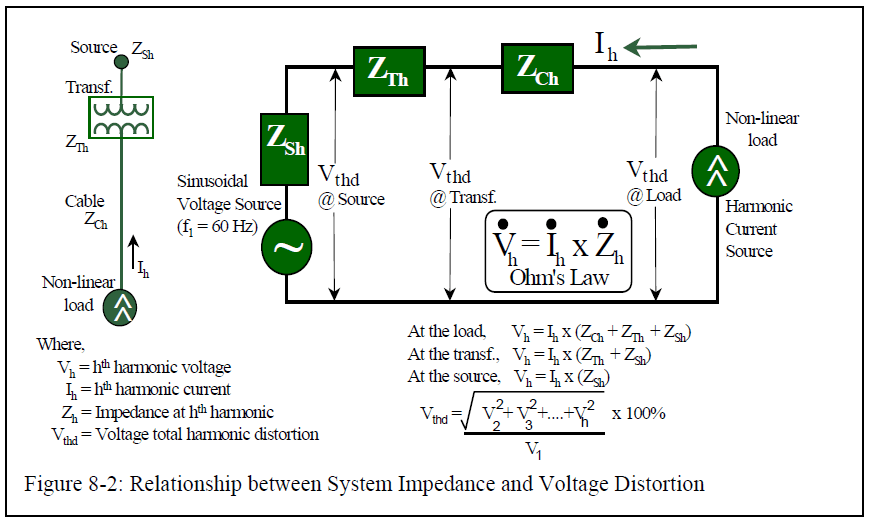
Another way to analyze the operation of the system with non-linear loads is to calculate the effect of each individual harmonic current as it flows through the various impedances of the distribution system. Fourier analysis tells us that the 2-pulse current drawn by the SMPS rectifier has a fundamental frequency component plus all of the odd harmonics (3rd, 5th, 7th, 9th, 11th, etc.) When modeling the distribution system, we can think of each SMPS as a generator of harmonic currents. Each harmonic current injected into the power system by a non-linear load will flow through the system impedance, resulting in a voltage drop at that harmonic frequency. The amount of voltage drop follows Ohm’s Law (Vh = Ih x Zh) where:
Vh = voltage at harmonic number h
Ih = amplitude of current harmonic h
Zh = impedance of the system to harmonic h.
Figure 8-2 shows the relationship between system impedance and the voltage and current distortion components at several points in a typical power system.
We can calculate the RMS value of the voltage or current distortion if we know the RMS values of all of the components. Parseval’s Theorem tells us that the RMS value of a waveform is equal to the square root of the sum of the squares of the RMS values of the fundamental component and all of the harmonic components of the waveform.
The fundamental is not a distortion component, so the RMS value of the distortion is just the square root of the sum of the squares of the harmonic components. Usually this is expressed as percentage of the value of the fundamental component and is called the Total Harmonic Distortion, or THD.
Voltage total harmonic distortion (Vthd) is calculated as:

Similarly, current total harmonic distortion is calculated as:

Voltage distortion then is a function of both the system impedance and the amount of harmonic current in the system. The higher the system impedance (ie. long cable runs, high impedance transformers, the use of diesel generators or other weak sources) the higher the voltage distortion.
In Figure 8-2, we see that voltage distortion is greatest at the loads themselves, since the harmonic currents are subjected to the full system impedance (cables, transformer and source) at that point. This is a characteristic most often misunderstood. It means that even if voltage distortion levels are low at the service entrance, they can be unacceptably high at the loads themselves. It also emphasizes the importance of keeping system impedances relatively low when servicing non-linear loads.
Voltage distortion can be minimized by removing the harmonic currents (Ih) and/or lowering the system impedance (Zh) to the harmonics.
Harmonics and Harmonic Mitigating Transformers (HMT’s) Questions and Answers
This document has been written to provide answers to the more frequently asked questions we have received regarding harmonics and the Harmonic Mitigating Transformer technology used to address them. This information will be of interest to both those experienced in harmonic mitigation techniques and those new to the problem of harmonics. For additional information visit our Website at www.mirusinternational.com.
