Published by Kerim Ozer, Senior Electrical Engineer, Enspec Power Ltd.
Email: kerim.ozer@enspecpower.com

A technical review of how passive harmonic filter types have an impact on network impedance profiles in terms of damping. A review of a harmonic filter design study was carried out for an industrial Plant, which included a total capacity of >100MW smelters, to mitigate the experienced harmonic limit exceedances against the Grid Code.
New Users which are to be connected to the grid, must meet the harmonic requirements specified by the Grid Code. In cases where harmonic emissions are not compliant, the installation of harmonic mitigation is required. Passive filters have traditionally been one of the most applicable & practical solutions to mitigate harmonic distortions. The most common passive filter types can be summarised as De-tuned, Single tuned, Second order and C-type filter.
Passive Harmonic Filter Design
Passive harmonic filters which consist of capacitors, reactors and resistors typically provide an alternative impedance path for harmonic currents and dampen the harmonic impedance profile. Based upon the specific system impedance profile, new users’ harmonic emissions and the background voltage distortion, the filters need to be custom designed for each site. Designs without consideration of the above identified criteria possibly result in poor filter performance and over/ under rated filter designs.
Study Case Site Overview
The industrial site included a total capacity of 100 MW smelters and 80 MW hydropower generators. The smelters were equipped with 2.5MVAr and 3.5MVAr detuned filters tuned at 185Hz and 270Hz. The site was connected to a 33kV Point of Common Coupling (PCC) via two parallel lines. To capture the network impedance profile accurately, the entire 33kV substation was modelled using IPSA 2.9 software package, this was done back to the 400kV network which is the point further additions did not lead to a significant change in the impedance as seen from the point of interest. A simplified Single Line Diagram (SLD) of the developed model is given in Figure 1.
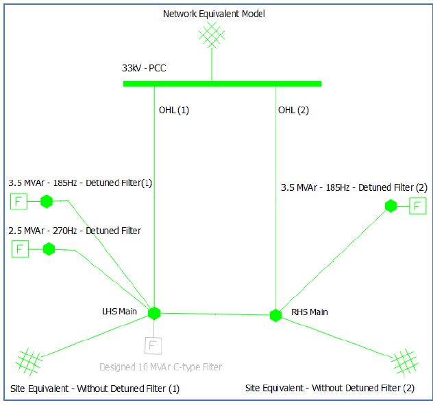
Figure 1 – Model used for analysis (IPSA)
Site’s Harmonic Issue Overview
Although the site is equipped with detuned harmonic filters, the historical harmonic measurements taken in 2019 and 2020 demonstrate that there are still harmonic limit exceedances at the 21st, 23rd, 25th, 33rd, 35th, 37th and 45th harmonic orders against the Grid Code requirements in the UK.
As can be seen from the impedance sweep given in Figure 2, it was found that the existing detuned harmonic filters did not sufficiently dampen the harmonic impedances at high orders. The existing de-tuned filters were only able to dampen the impedance at lower harmonic orders.
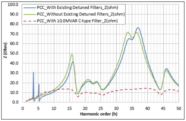
Figure 2 – Harmonic impedance scans
Proposed Harmonic Filter
Based upon the developed model, a filter design study was undertaken to reduce the harmonic exceedances. It was found that installation of a C-type harmonic filter (33kV, 10.0 MVAr, tuned to 200Hz with a QF of 0.50) mitigated the harmonic limit exceedances. The performance of the filter is indicated in Figure 2, Figure 3 and Figure 4.
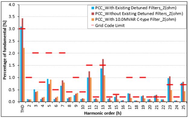
Figure 3 – Harmonic distortions, Orders 2 to 25
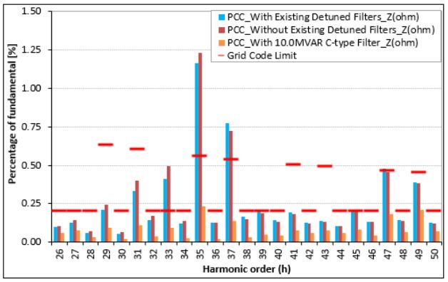
Figure 4 – Harmonic distortions, Orders 26 to 50
Conclusion and Recommendations
As can be seen from Figure 3 and Figure 4, the installation of a filter at the 33kV busbar ensures for mitigation of all harmonic voltage exceedances up to the 50th order, including THD at the 33kV PCC.
The following recommendations can be drawn:
- The existing detuned harmonic filters were not able to dampen the high order harmonic impedances.
- A detailed site model including the external network model was developed to represent the harmonic impedance profile of the network accurately.
- Site specific C-type filters were designed.
In conclusion, passive filter costs are much more significant than the engineering cost to properly design a site-specific filter. Thus, it is highly recommended a comprehensive harmonic filter design is undertaken to prevent an ineffective and/or incorrectly rated filter solution. Furthermore, design optimisation allows for individual components to be specifically calculated, ensuring for the most cost-effective design.
Enspec Power LTD.
6 Waterside Court, St Helens Technology Campus, Merseyside, WA9 1UA, United Kingdom
www.enspecpower.com 01744 610940
