Published by
- Raghawendra Sharan Mishra, Student, Department of Instrumentation & Control, Maharana Pratap College of Technology, Gwalior, India.
- Mr. Prasant Kumar, Assistant Professor, Department of Electrical Engineering, Maharana Pratap College of Technology, Gwalior, India.
IJSRD – International Journal for Scientific Research & Development | Vol. 5, Issue 09, 2017 | ISSN (online): 2321-0613
Abstract
Power quality is vital position recently because of the impact on electricity supplier’s equipment manufacture and consumer’s. Power quality is characterized in light of the fact that the variety of current, voltage and frequency in a power framework. It refers to an extensive sort of electromagnetic [EMI] phenomena that symbolize the contemporary and voltage at a given time and at a given area in the strength system. Currently, there are such a lot of industries the usage of technology for production and method unit. This generation calls for high quality and reliability of power supply system. The industries like equipments of manufacturing unit, semiconductor, computer, are very sensitive to the modifications of quality in power supply. Power Quality (PQ) issues encompass a wide variety of disturbances network along with impulse transient, voltage, harmonics distortion, sags/swells, flicker, , and interruptions. Voltage swells/sags can happens more regularly than other Power quality phenomenon. These voltage swells/sags are the maximum undesired power quality troubles inside the power distribution network. The goal and scope of this paper is look at of power excellent (PQ) occurrence in distribution structures.
Key words: Custom power, DSTATCOM, UPQC, DVR, PQ
I. INTRODUCTION
Power quality problem in the power system has showed importance since the late 1980s. The curiosity in Power Quality is related to all three parties worried with the power i.e. Equipment manufacturers utility businesses and electricity buyers. Problems affecting the electric supply that were once considered tolerable by the electricity utilities and users are now frequently taken as a problem to the users of every day equipment. Understanding power quality (PQ) can also be confusing at best. There are two phrases identified in electrical power techniques concerning the quality of power: first-rate power pleasant and terrible power first-rate. Power quality (PQ) can be utilized to explain a power supply that is at all times on hand, continuously within the voltage and frequency tolerances and has a pure sinusoidal wave shape to all equipment, because most equipment was designed on that basis [13]. Unfortunately, most of the equipment that is technical distorts the voltage [12] on the electric distribution system, leading to what is known as poor power quality (PQ).And therefore affecting other apparatus that was once designed with the expectation of constant undistorted voltage, and are for that reason sensitive [11] to power disturbances leading to reduced performance and can reason factors peculiar operation or premature failure. The cost of power quality (PQ) issues can be very high and include the cost of demurrage, lack of customer confidence and, in some cases, equipment damage. Indeed, power quality (PQ) is an important point in the relationship between suppliers and consumers[12] but might become a contractual gratitude that stress on improving power quality(PQ), availability, performance[8] and efficiency and these improvements will have: advantage for industrial customers (customized and flexible availability) and for suppliers utilities.
II. CLASSIFICATION AND IMPACT OF POWER QUALITY PROBLEMS
To make the investigation of PQ issues valuable, the different sorts of unsettling influences should be arranged by magnitude and duration.
A. Under voltages
Brief duration under -voltages are referred to as a “Voltage Dips [IEC]”/” Voltage Sags” Voltage sag [17, 18] is a reduction in the supply voltage magnitude followed by means of a voltage realization after a short period of time. Extreme framework loading, loss of age, inaccurately set transformer taps and voltage. controller unsettling disturbances, causes under voltage. Loads with a poor power factor or a basic lack of reactive power support on a method additionally contribute. Under voltage might also not directly lead to overloading issues as equipment places an increased current to keep power output (e.g. Motor loads).

Fig.1: An example of Under Voltage
B. Voltage Dips
The significant reason of voltage dips on a supply framework is a fault on the framework, i.e. sufficiently remote electrically that a voltage reregulation does not occur. Other sources are the applying of large loads and, occasionally, the apply of large inductive loads [18]. The effect on buyers may only assortment from the irritating (non-occasional light flicker) to the genuine (tripping of sensitive loads and associating of motors).
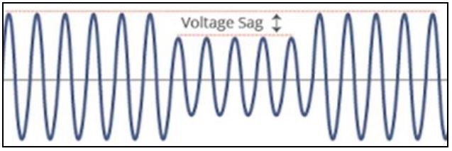
Fig. 2: An example of voltage sag
C. Voltage Spikes/Surges
Voltage surges/spikes are the opposite of dips – a arise that may be nearly instantaneous (spike) or happening over a longer duration (surge). These are regularly caused by arcing amid switching and lightning strikes operations on circuit breakers/contactors (fault clearance, circuit switching, particularly switch off of inductive burdens).
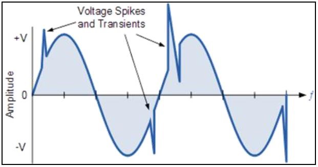
Fig. 3: An example of Voltage Surges/Spikes
D. Frequency Variations
Frequency fluctuations that are much enough to cause problems are most often envisage in small isolated networks, due to faulty. Different causes are not kidding overloads on a framework, or representative failures, however on an interconnected network, a solitary governor failure will not widespread disturbances influences of this nature.
E. Very short Interruptions.
Total interruption of electrical supply for length from couple of milliseconds to 1 seconds or 2 seconds. Causes: Mainly because of the opening and programmed reclosure of security gadgets to decommission a faulty section of the framework. The principle fault causes are insulator flashover insulation failure, and lightning

Fig. 4: An example of Very short Interruptions
F. Harmonic distortion
Current or voltage or waveforms expect non-sinusoidal shape. The waveform compares to the sum of other sine-waves with various stage and extent, having frequencies that are products of energy framework recurrence.
Causes: Classic sources: electric power machines working over the knee of the magnetization curve (alluring drenching), arc furnaces, rectifiers, welding machines and DC brush engines.
Modern sources: every single nonlinear load, for example, power electronics equipment including ASDs, , data preparing equipment, switched mode power supplies high efficiency lighting.
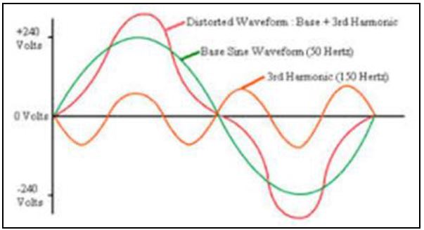
Fig. 5: An example of harmonic distortion
G. Voltage fluctuation
Oscillation of voltage esteem, amplitude regulated by a signal with frequency of 0 to 30 Hz. Causes: frequent start/stop of electric power motors (for instance elevators), Arc furnaces, oscillating loads. Consequences: Most outcomes are common to under voltage. The most perceptible outcome is the Flickering of lighting and screens, giving the impression of precariousness of visual observation.
III. VOLTAGE STABILITY METHODS
A. Distribution Static Compensator (DSTATCOM)
DSTATCOM is a Voltage source inverter (VSI) based static compensator device (FACTS controller, STATCOM) connected to keep up transport voltage lists at the required level by of providing or accepting receptive power in the conveyance framework. It is associated in shunt with dispersion connect with the assistance of coupling transformer. The single line diagram [SLD] of DSTATCOM is appeared in indicated fig.6. The DSTATCOM comprises of a VSI, dc voltage, energy storage device, an air conditioner filter and coupling transformer.
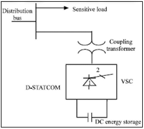
Fig. 6: Schematic diagram of DSTATCOM
In the power circuit, voltage source of inverter (VSI) converts DC voltage into controllable ac voltage, connected by ac filter and associated with AC distribution network through coupling transformer. The DSTATCOM can also absorbed and rely active power, by using energy storage in sufficient amount or renewal energy resources. The working rule of DSTATCOM that it constantly direction and screens the load currents and voltages, decides the measure of remuneration required by distribution system for a need of disturbances. In this plan the active power flow is controlled by the point between the ac framework and Voltage source inverter (VSI) voltages, the reactive power flow is controlled by the distinction between the adequacy of these voltages. The DSTATCOM works in both current and voltage control modes.
B. Static Series Compensator
Static series compensator is otherwise called Dynamic Voltage Restorer (DVR). It is a high-speed switching power electronic controlling gadget. Otherwise called series voltage booster. Dynamic Voltage Restorer (DVR) is a series connected custom power electronics device, designed to inject a dynamically regulated voltage in phase and magnitude in to distribution line by means of coupling transformer to correct load voltage. The summed up square diag. of DVR is appeared in the Fig 7.

Fig. 7: Schematic diagram of DVR
It consists of an energy storage device or renewal energy resources, a boost converter (dc to dc), voltage source inverter (VSI), ac filter and coupling transformer, connected in series. Here dc capacitors elements is used as energy storage device, which is interface by a boost converter. The boost converter controlled the voltage over the dc link capacitor that utilizations as a typical voltage hotspot for the inverters. The inverter methodology generates a compensating voltage, which is inserted into distribution system through series matching transformer. In the case of voltage reregulation, the Dynamic Voltage Restorer (DVR) controllers generate a reference voltage, and compare it with inject synchronized voltage and source voltage to maintain the load voltage constant. The energy storage elements provide the required power to synchronized injected voltage.
The ac filter evacuates the impacts on winding of coupling transformer and power electronics switching losses of control signal producing systems for voltage source of inverter (VSI).
Where Vs(t) supply voltage, Vi(t) infusion voltage of DVR, and Vl(t) load voltage are associated in arrangement. the load voltage is given as:
Vl(t)=Vi(t)+Vs(t)
Along these lines DVR is supposing as an external voltage source of controlled frequency, phase angle, and abundancy. The point of utilizing DVR is to keep up the phase angle, amplitude and of fixed load voltage.
C. Unified Power Quality Compensator (UPQC)
It is a typical operation of shunt active and arrangement conditioner. Shunt active power filter strength of the current compensation, series active power filter strength of voltage compensation allow quelling of various power quality problem. The single line diagram (SLD) of unified power quality compensator (UPQC) is appeared in Fig 8. To repay under voltage shunt associated active conditioner need to absorb active power injected by arrangement compensator in arrangement to remunerate overvoltage active conditioner retain active power keeping DC connect charged. Two kind of are unified power quality compensator (UPQC) are proposed in literature overviews. One is called Left-Shunt UPQC and another is known as Right Shunt UPQC. The general execution of right-shunt unified power quality compensator (UPQC) is superior to anything left-shunt unified power quality compensator (UPQC). At the point UPQC is related between two feeders by then, called IUPQC.

Fig. 8: Schematic diagram of UPQC
IV. CONCLUSION
This paper Discussed a brief review of power devices which has been installed in power distribution network to remove various power quality fluctuations;, flicker, power factor decrease, dip, current harmonics, voltage sag/swells. These power electronics devices applied at the distribution system with purpose of protect whole plant, loads, feeder. The A. Distribution Static Compensator (DSTATCOM), which is associated in shunt can give great power quality in both appropriation and transmission. Unified Power Quality Compensator (UPQC) is the key of power devices, can regulate both current and voltage related problems at the same time. This entire device integrated to form custom power area.
REFERENCES
[1] M.B. Brennen and B. Banerjee, “Low cost, high performance active power line conditioners”. Proc. Conf. PQA 94, Part 2, Amsterdam, The Netherlands, Oct. 24- 27, 1994.
[2] J.M. Powell, “Power conditioning system and apparatus” U.S.Patent 4, 544, 877, Oct.1, 1985.
[3] “Comprehensive monitoring—covering all aspects” http://www.powerquality.com/art0031/art1.ht m
[4] Dennis Stewart, “Cover Story: Power monitoring technology Dispelling—metering myths” http://www.powerquality.com/articles.html
[5] Marty Martin, “Common power quality problems and best practice solutions,” Shangri-la Kuala Lumpur, Malaysia 14. August 1997.
[6] David Chapman, “Electrical design—A good practice guide”,CDA Publication 123, Dec. 1997.
[7] D.D. Sabin and A. Sundaram, “Quality enhances reliability”.IEEE Spectrum, Feb. 1996. 34-41.
[8] N.G. Hingorani, “Introducing custom power,” IEEE Spectrum, Jun. 1995, 41-48.
[9] “Details of equipment sensitivity,” http://www.powerquality.com/pqpark/pqpk1052.hm.
[10] A. Rash, “Power quality and harmonics in the supply network a look at common practices and standards,” in Proc. on MELECON’ 98, Vol.2, pp.1219-1223, May1998.
[11] R.C. Sermon, “An overview of power quality standards and guidelines from the end-user’s point-of-view,” in Proc. Rural Electric Power Conf., pp. 1-15, May 2005.
[12] IEC 61000-4-30, “Testing and measurement techniques – Power quality measurement methods,” pp. 19, 78, 81,2003.
[13] EN 50160, “Voltage characteristics of electricity supplied by public distribution systems,” 1999.
[14] M.H.J. Bollen, Understanding Power Quality Problems: Voltage Sags and Interruptions, New York, IEEE Press, 1999
[15] E. Styvaktakis, M.H.J. Bollen, I.Y.H. Gu, “Classification of power system events: Voltage dips,” 9th International IEEE Conference on Harmonics and Quality of Power, Orlando, Florida USA, Vol. 2, pp. 745- 750, October 1-4, 2000.
[16] A. Domijan, G.T. Heydt, A.P.S. Meliopoulos, S.S. Venkata, S. West, “Directions of research on electric power quality,” IEEE Transactions on Power Delivery, Vol. 8, pp. 429-436, 1993.
[17] R.C. Dugan, M.F. McGranaghan, and H.W. Beaty, Electric Power Systems Quality, New York, McGraw-Hill, 1996.
[18] J. Arrillaga, N.R. Watson and S. Chen, Power system quality assessment, John Wiley and Sons, 2000.
[19] IEEE Working Group on Voltage Flicker and Service to Critical Loads, “Power Quality—Two Different erspectives,” presented at IEEE/PES 1900 Winter Meeting,Atlanta, GA, Feb. 1990.
[20] IEEE Recommended Practice for Monitoring Electric Power Quality, IEEE Standard 1159– 1995.
[21] H.J. Kim, K.C. Seong, J.W. Cho, J.H. Bae, K.D. Sim, S. Kim, E.Y. Lee, K. Ryu and S.H. Kim, “3 MJ/750 kVA SMES System for Improving Power Quality,” IEEE Trans. on Superconductivity, Vol. 16, issue 2, pp. 574- 577, June,2006.
[22] W.M Grady, M.J. Samotyj, and A.H. Noyola, “Survey of active power line conditioning methodologies,” IEEE Trans. Power Delivery, Vol. 5, pp. 1536–1542, 1990.
[23] B. Singh, K. AL Haddad and A. Chandra, “A review of active filters for power quality improvement,” IEEE Trans. Ind. Electron., Vol. 46, pp. 960–970, 1999.
