Published by testguy, November 23, 2019. Website: testguy.net
Power Factor, Unbalance and Harmonics
Electrical loads are often composed of more than just pure resistance, the combination of resistance and reactance in an AC system is called the impedance. Reactance comes in two forms: inductive and capacitive, both of which do not contribute to “useful” work on the power system.
Power Factor is a way to characterize how much electrical power goes toward producing useful work such as light, heating, or machinery. Low power factor means a large amount of energy is being lost in the system in the form of wasted heat, which generally equates to higher energy bills and equipment degradation.
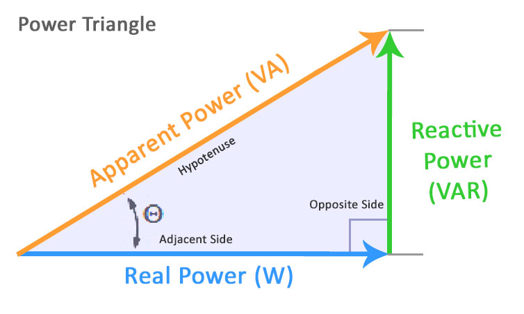
Fig1. Three types of power – true, reactive, and apparent – relate to one another in trigonometric form.
Motors, solenoids and pumps typically have impedances that are combinations of resistance and inductive reactance, which vary with the mechanical load on the machine. Capacitors have impedances that are combinations of a typically small resistance and larger capacitive reactance component.
When reactance is present in an AC system, the voltage and current sine waves will shift out of phase from each other. Voltage leads current with inductive reactance and Current leads voltage with capacitive reactance, the two cancel each other out.

Fig2. When reactance is present in an AC system, the voltage and current sine waves will shift out of phase from each other.
Low power factor tends to occur in industrial facilities that contain a large number of motors or other inductive loads. Utility companies typically charge large industrial and commercial customers a higher rate for low power factor.
Unbalance occurs in three-phase power systems when single phase loads (lighting, office equipment, etc.) do not draw the same amount of current on each phase, resulting in greater stress on the neutral conductor. An ideal condition occurs when the loads are balanced, meaning that the voltage and current phases are exactly 120 degrees apart from each other, although the currents might not be in-phase with the voltages.

Fig3. Unbalance occurs in three-phase power systems when single phase loads do not draw the same amount of current on each phase.
A balanced three-phase 4-wire wye system will have zero current on the neutral wire. The amount of current on the neutral wire in an unbalanced system will increase as the unbalance increases, this could result in overheating and risk of fire.
Motors being driven by unbalanced voltages will result in a small motor torque working in the opposite direction from the motor rotation, a phenomena known as counter-torque. When this condition occurs, part of the energy delivered to the motor will work against itself.
Harmonics are a form of waveform distortion that occurs in circuits containing semiconductor based electronics such as LED lighting, switching power supplies, electronic ballasts, computers, robotics, test equipment, etc. These “non-linear” loads impose higher frequency sine waves on the system, which result in more power lost in the form of wasted heat.
The excess heat produced by harmonics can have detrimental effects on a power system. Transformers are especially susceptible to damage caused by harmonics due to stray “eddy currents” which circulate in the iron core and produce excess heat.
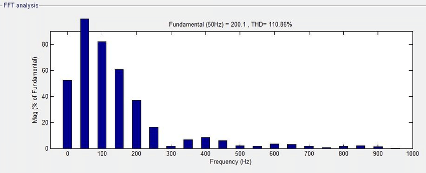
Fig4. Harmonics are identified by their frequency in multiples of the “fundamental” or main frequency.
Harmonics are identified by their frequency in multiples of the “fundamental” or main frequency (60Hz in the United States). For example, the third harmonic in a 60 Hz system would be 180 Hz (60×3 = 180) and the 5th harmonic would be 300 Hz (60 x 5 = 300).
The magnitude of each harmonic frequency can be measured using power quality meters and are generally displayed in the form of a harmonic spectrum. Total harmonic distortion (THD) and total demand distortion (TDD) are sometimes used with power quality meters to simplify harmonic distortion as a single measurement rather than an entire spectrum.

Thank you, I have been seeking for details about this subject for ages and yours is the best I’ve located so far.
LikeLike
Valuable info. Lucky me I discovered your site by chance,
and I’m stunned why this twist of fate did not took place earlier!
I bookmarked it.
LikeLike