Published by Omar H. Abdalla, Fellow Egyptian Society of Engineers, Life Senior Member IEEE.
Prof. O. H. Abdalla is with the Department of Electrical Power and Machines Engineering, Faculty of Engineering, 1 Sherief Street, P.O. Technology, P.C. 11792, Helwan, Cairo, Egypt. (e-mail: ohabdalla@ieee.org).
Conference Paper: Keynote Lecture (KL-REN-5), International Conference on New Energy and Environmental Engineering (ICNEEE), Future University, Cairo, Egypt, 11-14 April, 2016.
Abstract
The objective of this paper is to provide basic information on the technical design specifications, criteria, technical terms and equipment parameters required to connect PV systems to the distribution networks in Egypt. Successful connection of a PV system should satisfy requirements of both the ssPV Code and Electricity Distribution Code. The ssPV Code specifies the special requirements for the connection of small-scale PV systems to the Low Voltage (LV) distribution network. The Electricity Distribution Code (EDC) sets out the rules and procedures to regulate technical and legal relationship between distribution utilities and users of the distribution networks. The aim is to maintain optimal operation, safety and reliability of the power system. The technical specifications including permitted voltage and frequency variations in addition to power quality measures such as limits of harmonic distortion, phase unbalance, and flickers. Small-scale PV system operational limits, capability requirements, power factor, safety, protection, synchronization, etc. will be explained and discussed. In addition, the roles stipulated in the EDC for connecting distributed generating units to the distribution networks are briefly presented.
Index Terms—Distribution networks, Photovoltaic systems, PV integration, Distribution code, PV connection code.
I. INTRODUCTION
There has been a continuous increase in the share of the renewable resources in generating the required electricity to cope with increasing demand. Future electricity generation plans countries around the world expect more contribution of renewable energies in the electricity generation mix. Some utilities set a target of 20% renewable energy of total required energy by 2020. Others expect 50% by 2050. Among various renewable energies, wind and solar are the most promising resources and proved to be efficient in real applications at decreasing competitive kWh costs.
The increasing ratio of renewable energy sources to be connected to electric power systems has resulted in technical issues related to power quality, capacity, safety, protection, synchronization, etc. Electricity utilities and regulators have issued regulation roles for connecting renewable energy sources to power grids at distribution level and transmission level.
An overview of recent grid codes for PV power integration is presented in [1]. It provides a survey of grid codes, regulations and requirements for connecting PV systems to LV and MV networks, including power quality concerns and anti-islanding issues. A guide to PV interconnection issues [2] has been developed by the Interstate Renewable Energy Council, North Carolina Solar Center, USA. Interconnection issues cover all steps for connecting a small scale renewable energy system to the utility network, including technical, contractual, and rates and metering issues. German codes for connecting PV systems to medium voltage power grid are described in [3]. A comparison of Germany’s and California’s interconnection processes for PV systems is discussed in [4]. The IET has developed the Standards: “Code of Practice for Grid Connected Solar Photovoltaic Systems [5]. The National Energy Regulator of South Africa has approved the “Grid Connection Code for Renewable Power Plants Connected to the Electricity Transmission System or the Distribution System” [6].
This paper concerns with technical design specifications and criteria, technical terms and equipment parameters required to connect small-scale PV systems to the distribution networks in Egypt. Successful connection of a PV system should satisfy requirements of both the ssPV Code [7] and the Electricity Distribution Code [8].
The ssPV Code specifies the special requirements for the connection of small-scale PV systems to the Low Voltage (LV) distribution network. Although the ssPV code is all complementary documents that entail obligatory provisions for customers seeking ssPV installations [7], the customer should also satisfy the requirements of the Distribution Code. Technical terms of these codes should be clearly understandable by all parties to correctly implement the rules and procedures described in the codes.
The Electricity Distribution Code is a document that contains a set of rules and procedures to regulate technical and legal relationship between a Distribution System Operator (DSO) and users of the distribution network. The objective is to establish the obligations and responsibilities of each party; i.e. the DSO and all network users; namely, subscribers, distributed electricity production units, etc. This will lead to maintain optimal operation, safety and reliability of the power system.
The technical specifications of integrating small-scale PV systems to the distribution networks include permitted voltage and frequency variations in addition to power quality measures such as limits of harmonic distortion, phase unbalance, and flickers. PV systems operational limits, capability requirements, power factor, safety, synchronization, protection, etc. will be explained and discussed.
Section II presents a brief review of power quality terms and criteria referred to in the ssPV Code. Section III describes the technical requirements and criteria for connecting small scale PV systems to the low voltage distribution networks in Egypt. Section IV summarizes the technical requirements and criteria for connecting distributed generations to distribution networks as stipulated in the Electricity Distribution Code.
II. REVIEW OF POWER QUALITY CRITERIA
This section reviews briefly power quality issues related to both the Distribution Code and the small-scale PV Code in order to understand respective terms in the codes. Definitions, mathematical description, causes and impacts of various parameters are explained.
A. Voltage Flicker
If a load such as an arc furnace causes voltage variations at the PCC with spectral characteristics in the range of a fraction of one Hz and about one third of the system frequency, this effect is known as voltage flicker. It is a characteristic where a high frequency (𝜔𝑜) sinusoid is modulated by a low frequency sinusoid (𝜔𝑓). In mathematical form,

Intensity of flicker is given by,
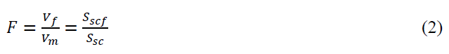
𝑆𝑠𝑐𝑓 = short-circuit MVA at the electrode tip
𝑆𝑠𝑐 = short-circuit MVA at the PCC
The IEC has developed a flicker meter which measures flickers in terms of fluctuating voltage magnitude and its corresponding frequency of fluctuations. It uses a software technique to convert flicker voltage fluctuations into the following two statistical quantities:
- Short-term flicker severity (PST)
- Long-term flicker severity (PLT)
The flicker meter takes measurements automatically at ten minutes intervals. The short-term flicker severity is calculated every 10 minutes. The indicator PST having a value of 1 represents the level of visual severity at which 50% of people would perceive flicker in a 60 W incandescent bulb. The long-term flicker severity (PLT) is a combination of 12 PST values.
B. Voltage Unbalance
A 3-Ph power system is called Balanced if the 3-Ph voltages (& currents) have the same amplitude, and are phase shifted by 120o with respect to each other. If either or both of these two conditions are not met, the system is called Unbalanced.
The relation between the symmetrical components (V0, V1, V2) and the phase components (VA, AB, VC) is,
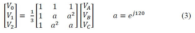
V0, V1 and V2 are the zero-, positive-, and negative-sequence components, respectively. According to the EN-50160 and IEC-61000-3-x, standards the voltage unbalance (V2U) is defined as,
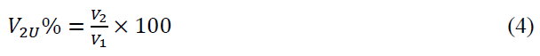
The standards stipulate the following voltage unbalance limits:

These values are measured as 10-minute average value with an instantaneous maximum of 4%.
Causes of unbalance include generators, transformers, unbalanced impedances of long, non-transposed low voltage lines, unbalanced load currents, 1-phase loads on 3-phase systems, etc. Unbalance can adversely affect equipment such as motors and transformers by increase heating and reduce efficiency.
C. Harmonics
Linear loads such as incandescent lighting and heating draw currents proportional to applied voltages, whilst non-linear loads computers and adjustable speed drives draw currents during a part of the voltage cycle. The currents of nonlinear loads contains odd harmonics (3rd, 5th, 7th, etc.). Harmonic currents interact with source currents, leading to voltage harmonics. These harmonic components are superimposed on the fundamental voltage component resulting in a distorted voltage wave, which has the following Fourier form:

Where

Having determined the fundamental U1 and harmonic components (U2, U3, U4, etc.), we can calculate the Total Harmonic Distortion (THD),
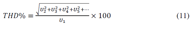
Harmonic currents can cause problems such as equipment heating, false tripping of circuit breakers, neutral line overloading, increased skin effect, etc. Therefore, electricity codes stipulate limitations on THD in networks.
III. SMALL-SCALE PV CONNECTION CODE
A. General Design Requirements
The ssPV Code [7] specifies the technical requirements and criteria for connecting small scale PV systems to the low voltage distribution networks in Egypt. The small scale PV system is defined in practice as a PV electric energy generation source rated at up to 500 kW including the PV panels, converters, control devices, and protection gears within a customer’s network that operates in synchronism with the 3-phase LV distribution networks.
The ssPV system shall be type approved. Design qualification and type approval of PV modules are based on IEC-61215 / IEC 61649 Standards. The maximum size of the ssPV system is limited by the rating of the CB at the supply point on the premises, and the allowable voltage range at the LV side of the MV/LV transformer and the voltage at the farthest point of the feeder.
The technical requirements and criteria stipulated in the ssPV code are summarized in the following subsections.
B. Power Quality Requirements
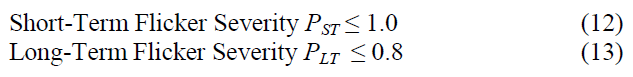
The quality of electric power supplied at the PCC is governed by relevant practices and standards. The total flicker severity at the PCC, including the ssPV system and both existing and future loads, shall not exceed the following levels (for LV and MV):
The THD of the current produced from the ssPV system at rated output shall limited to be < 5%, while the individual harmonic components are listed in Table I, in accordance to the IEC 61727-2004 Standard.
TABLE I: LIMITS OF CURRENT HARMONIC DISTORTION AT THE PCC

C. Power Factor
Although, the ssPV Code prevents injection of reactive power from the PV system to the distribution network, it allows the customer to draw power at 0.9 pf lag limit (unless other pf is agreed).
D. Direct Current Injection
The limit of direct current (d.c.) injection into the network shall not exceed 0.5% of the rated a.c. ssPV current supplied at the PCC. If this limit is violated, the inverter must disconnect within 500 ms.
E. Synchronization
The ssPV system shall be synchronized to the network, through the static inverter after satisfying the following conditions:
- Frequency difference ≤ 0.3 Hz,
- Voltage difference ≤ 5%, and
- Phase angle difference ≤ 20°.
F. Safety and Protection
For safety and protection of the ssPV system, the code specifies the conditions of disconnection from the network as follows:
- If the voltage (V) of the network violates the limits as listed in Table II,
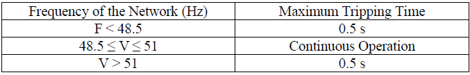
- If the frequency (F) of the network violates the allowable operating limits as listed in Table III,
- Loss-of-grid conditions, or
- If the direct current injection exceeds the limit (0.5%).
TABLE II: VOLTAGE RANGES AT THE PCC AND MAXIMUM TRIPPING TIMES

TABLE III: FREQUENCY RANGES OF THE NETWORK AND MAXIMUM TRIPPING TIMES
For short-circuit protection, the ssPV shall comply with the IEC 60364-7-712 Standard titled “Electrical Installations of Buildings”. It concerns with the requirements for special installations or locations of solar PV power supply systems.
G. Switching Arrangement
Switching arrangement for disconnecting the ssPV system from the network in abnormal conditions is described in detail in the code. The abnormal conditions include violation of the limits of network voltage or frequency as specified in Table II and Table III, respectively. At least two series disconnecting switches are required; one of them shall be an electromechanical switch, while the other may be embedded in the inverter. The objectives are to ensure personnel safety and to avoid equipment damage. In response to network recovery, the ssPV system shall not re-energize the network for 1 minute.
H. Islanding
To comply with the ssPV connection code requirements, unintended islanding condition shall be prevented. At least, one method of active islanding detection shall be used. Active methods introduce small perturbation to the system and monitor the response to determine if the PV and the network are still connected [9]. If this affects the system parameters within prescribed requirements, the active circuit will causes the inverter to cease delivery of power. The ssPV system shall comply with the requirements of IEC 62116 Standard which specifies testing procedure of islanding prevention methods for utility-interactive PV inverters. Experimental studies are presented in [10]. In response to network recovery after islanding, the ssPV system shall not re-energize the network for 1 minute.
I. ssPV Earthing
Earthing of the ssPV electrical installation system shall comply with the requirements of the SANS 10142-1: Code of Practice Wiring of Premises. The ssPV Code requires that the ssPV system be protected by an earth leakage unit separated from customer network earth leakage units. The ssPV system inverter shall be appropriately using an earth leakage circuit breaker capable of responding to d.c. fault currents.
J. Energy Metering Arrangements
Metering circuits and types are described in the ssPV code, including unidirectional and bi-directional, with single or separate meters.
IV. ELECTRICITY DISTRIBUTION CODE
The Electricity Distribution Code (EDC) has been issued and effective since March 2010 [8]. The aim of the EDC is to regulate the electricity distribution and connection to the subscribers in a safe and stable manner, in addition to regulate connecting the distributed generating units with distribution networks. The code consists of 14 chapters including objectives, validity, planning of assets, contracting, quality of supply, distributed (or scattered) generation, plans for dealing with emergencies, metering code, in addition to legal and other electricity distribution regulating issues. Our concern here is the technical requirements of connecting distributed generation as described in chapter 6 of the EDC.
A. Distributed Generation (DG)
Chapter 6 of the Distribution Code stipulates the roles for connecting the distributed generating units to the distribution networks. The roles are briefly described here. The licensed distributor is obliged to facilitate connection of the DG units and access to use the network provided that they are compliant with the code requirements including technical, environmental and safety. The DG provider is obliged to continue operating the connected units at 50 Hz and be within the allowable frequency limits defined in the Transmission Grid Code [11]. According to the IEEE Standard 1547 – 2003 [12], the following specifications should be considered:
- The DG unit should not cause network voltage changes outside the allowable limits (± 5%)
- The unit earthing should not affect the consistency of adjusting protection devices of earth faults.
- The unit should not cause voltage fluctuations or flicker outside the allowable limits.
- The unit should not allow injecting direct current higher than 0.5% of the total rated A.C. current, at the PCC.
In addition, the DG unit should pass all technical tests specified in the IEEE standard 1547 – 2003, including:
- Performance during voltage transients
- Synchronization
- Protection from electromagnetic interference
- Limits of direct current
- Voltage harmonics
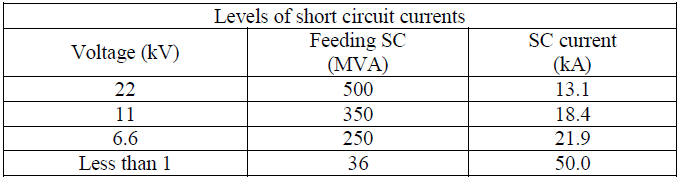
The negative-sequence voltage component due to the DG should not exceed 1% at the PCC. The use of the DG should not lead to increasing the THD at the PCC exceeding the limits listed in Table IV and Table V (IEEE 519 – 1992, Standard). The DG units should not cause inductive interference exceeding the limits stipulated in the IEEE Standard C37.90.2. In designing and operating the DG, the short-circuit limits listed in Table VI should not be exceeded.
TABLE IV: LIMITS OF VOLTAGE HARMONIC DISTORTION AT THE PCC
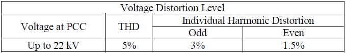
TABLE V: LIMITS OF CURRENT HARMONIC DISTORTION AT THE PCC
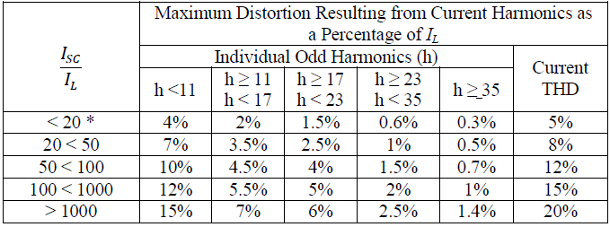
Notes:
ISC = maximum short-circuit current at the PCC
IL = maximum load current of the fundamental component at the PCC
TABLE VI: SHORT-CIRCUIT LIMITS AT THE PCC
V. CONCLUSION
The paper has presented the technical design specifications, criteria, technical terms and equipment parameters required to connect PV systems to the distribution networks in Egypt. The specifications, terms and parameters are extracted from the ssPV Code [7] and Electricity Distribution Code [8]. The presented technical specifications and criteria are useful for researchers, design engineers, and installations engineers working in the field of connecting small-scale PV systems into distribution networks. For successful connection of small-scale PV systems to distribution networks, it is recommended to read the full versions of the ssPV Code and the Electricity Distribution Code.
REFERENCES
[1] B. I. Craciun, T. Kerekes, D. Sera, and R. Teodorescu, “Overview of recent grid codes for PV power integration,” 13th International Optimization of Electrical and Electronic Equipment, OPTIM, Brasov, Romania, 24-26 May 2012, pp. 959-965.
[2] C. Larsen, B. Brooks, and T. Starrs, “Connecting to the Grid – A Guide to PV Interconnection Issues,” 3rd ed., Interstate Renewable Energy Council, IREC, North Carolina Solar Center, USA, 2000, pp. 1-37.
[3] E. Troester, “New German Codes for connecting PV systems to medium voltage power grid,” 2nd International Workshop on Concentrating Photovoltaic Power Plants: Optical Design, Production, Grid Connection, Dramstadt, Germany, 9-10 March, 2009, pp.1-4.
[4] A. Tweedie and E. Doris, “Comparing Germany’s and California’s interconnection processes for PV systems,” National Renewable Energy Laboratory, NREL, Clorado, USA, July 2012, pp. 1-60. Available: http://www.nrel.gov/docs/fy11osti/51814.pdf
[5] IET Standards, “Code of Practice for Grid Connected Solar Photovoltaic Systems,” IET, UK, 2014, pp.1-120.
[6] Grid Connection Code for Renewable Power Plants (RPPs) Connected to the Electricity Transmission System (TS) or the Distribution System (DS) in South Africa, Version 2.6, National Energy Regulator of South Africa, NERSA, South Africa, 2012, pp. 1-61.
[7] Technical Requirements for Connecting Small Scale PV (ssPV) Systems to Low Voltage Distribution Networks, ssPV Code, Egyptian Electric Utility and Consumer Protection and Regulatory Authority, EgyptEra, Cairo., Egypt, 2014, pp. 1-9. Available: http://www.egyptera.org
[8] Electricity Distribution Code, Egyptian Electric Utility and Consumer Protection and Regulatory Authority, EgyptEra, Cairo., Egypt, 2010, pp. 1-29. Available: http://www.egyptera.org
[9] W. Bower and M. Ropp, “Evaluation of islanding detection methods for utility-interactive inverters in photovoltaic systems,” Sandia National Laboratories, Tech. Rep. SAND2002-3591, New Mexico, CA, 2002.
[10] F. Belloni, P. Groppelli, C. Chiappa, and C. Gandolfy, “Test of anti-islanding protections according to IEC 62166: an experimental feasibility assessment,” The 48th International Universities Power
Engineering Conference, UPEC 2013, Dublin, UK, 2-5 Sept. 2001, Available: http://www.xplore.ieee.org
[11] Transmission Grid Code, Egyptian Electricity Transmission Company, EETC, Cairo, Egypt, Available: http://www.eetc.net.eg/grid_code.html
[12] IEEE Standard for Interconnecting Distributed Resources with Electric Power Systems, IEEE Std 1547™-2003, Standards Coordinating Committee 21, IEEE, June 2003, pp. 1-16.
Author
Omar Hanafy Abdalla (M’76–SM’83–Life SM’2014) was born in Cairo, Egypt on 11 May, 1945. He received the Ph. D. degree in electrical engineering from the University of Liverpool, England, in 1979. Since B. Sc. graduation in 1967, he has been appointed in various positions in university teaching and research: Engineer 1967, Demonstrator 1970, Lecturer 1976, Associate Professor 1983, Professor 1987, Head of the Department of Electrical Power & Machines Engineering 1987, Vice-Dean for Postgraduate Studies and Research 1997, Dean of the Faculty of Engineering 2002, Professor Emeritus 2005-now. He has published over 120 papers and appointed as a Reviewer for many national and international periodicals and conferences. He is a member of the Editorial Board of the International Journal of Emerging Electrical Power System, and the Editorial Board of the Journal of Electrical Systems.
From January 2007 to February 2014, he was on leave from the University of Helwan; working (System Studies Advisor) with Oman Electricity Transmission Company, Muscat, Sultanate of Oman. He was involved in various technical activities and leading strategic planning and transmission system studies such as the Transmission Master Plan 2014-2030, Five Year Annual Transmission System Capability Statements, planning and design of new generation and bulk industrial load connections, HV grid-stations, transmission lines of 400kV, 220kV and 132kV levels, network expansions and reinforcements, Pre-Investment Appraisal Documents for new projects, etc. He was also involved in the technical studies and practical operation of the interconnection between Oman and the United Arab Emirates.
Prof. Omar H. Abdalla received the Encouraging Prize of the State in Engineering Sciences, 1984, the First Class Medal of Sciences and Arts, 1985, and Helwan University Appreciation Prize in Engineering Sciences and Technology, 2006/2007.
