Published by David Mueller, E. H. Camm.
Abstract
Power quality standards exist to guide the interconnection requirements of large wind and solar plants. IEEE guidelines exist for flicker and harmonics, while IEC guidelines exist for the measurement criteria of power quality phenomena and the characterization of wind turbine equipment. There are also some uniform guidelines for low voltage ride through (LVRT) of large plants. The presentation gives an overview of these standard and requirements, and also suggests some application guidelines not covered in the standards themselves.
Index Terms— Power system harmonics, wind power plants, wind turbines, flicker, low voltage ride through.
List of Acronyms
| CSP | Concentrated Solar Plants |
| CP | Cumulative Probability |
| CP95% | CP 95% Level |
| LGIA | Large Generator Interconnection Agreement |
| PCC | Point of Common Coupling |
| PES | IEEE Power and Energy Society |
| PV | Photovoltaic |
| TDD | Total Demand Distortion |
| THD | Total Harmonic Distortion |
| UWIG | Utility Wind Integration Group (now UVIG) |
| UVIG | Utility Variable Integration Group (formerly UWIG) |
| WPP | Wind Power Plant |
I. Introduction
Utility scale wind and solar power plants can be characterized as systems that are 20MW or more of output, and have a transmission system interconnected at a voltage greater than 69kV. Smaller and more dispersed systems have a lower production output and are connected on distributions systems with a voltage lower than 69kV.
Power quality is the study of compliance when various systems will operate properly on the power system, and that they will not interfere with the operation of other devices on the system. Power quality disturbances include outages, voltage variations (high or low), and waveform distortions. The power quality issues of wind and solar plants depend upon the type of facility and its power conversion technology.
II. Types of Wind Turbine Generators
Typically wind turbine generators do not utilize conventional line-connected synchronous machines, but rather other machine designs. The evolution of the wind turbine design has allowed for the capture of greater power over more variable wind conditions. The type of wind turbine generator is important in evaluating their power quality characteristics. The Western Coordinating Council was instrumental in developing various stability models, where different wind turbine types were introduced [1]. The IEEE Wind and Solar Plant Collector WG has also published a paper on wind turbine types [2].
The Type 1 wind turbine generator utilizes an induction motor. It operates near synchronous speed, with a minor amount of speed variation from the slip of the motor. The operation of this machine has been described as being like “blowing on a fan”.
The Type 2 wind turbine generator utilizes a wound rotor induction generator. The rotor terminals are brought external to the motor via slip rings, and the rotor resistance is controlled. This configuration allows a higher slip and a wider speed control range than available with the Type 1 wind turbine generator.
Type 1 and Type 2 wind turbine generators consume reactive power, so these turbines include power factor correction. These power factor correction capacitors are an important resonance consideration when a harmonic study is performed.
Type 3 wind turbine generators are also commonly referred to as the Doubly-Fed Assynchronous Generator (DFAG) or as a Doubly-Fed Induction Generator (DFIG). In this configuration the rotor is separately powered through a double-conversion power electronic bridge. The power delivered by the machine is the net result of both power circuits. The advantage of the Type 3 wind turbine is controllability of the machine over a wide-speed range, and the ability to control power factor from leading to lagging as required by the grid. Typically the power conversion in the rotor circuit is about 30% of the overall capacity of the machine.
Type 4 wind turbine generator utilizes full power conversion via voltage source inverters. The generator operates at the mechanical optimum speed, while the inverters convert the power back to line frequency.
Type 3 and Type 4 wind turbine generators utilize power electronics, so harmonics are usually monitored and studied. It is important to realize that these inverters utilize PWM style controls, so that the current harmonics to the grid should be low (Ithd<5%) in either case.
III. Types of Solar Power Plants
Concentrated solar plants (CSP) concentrate sunlight from lenses or mirrors with tracking systems to focus a large area of sunlight into a small beam. The concentrated heat is then used as a heat source at a central tower generates steam which powers a conventional synchronous machine.
Photovoltaic (PV) systems convert light into DC power using solar cells. Individual cells are connected into arrays, where the DC power is converted through an inverter for connection to the power grid. Large PV inverters utilize PWM style controls, and the harmonic issues are very similar to Type 4 wind turbine generators.
IV. Compliance with Harmonic Standards
In the United States, IEEE Std 519 [3] is the important standard for governing the harmonics considerations of wind power plants although certain limitations apply. Article 9.7.6 of the Standard Large Generator Interconnection Agreement (LGIA), used by many electric reliability organizations, requires generating facilities to limit excessive harmonic distortion in accordance with IEEE Std 519. The application of the IEEE Std 519 limits to wind plants is an area of practice that is evolving. Fundamentally, it is important to realize that the current limits in the recommended practice do not apply to harmonic currents that are absorbed by the wind plant from the background harmonic source of the grid. Series resonance from the collector cable capacitance can easily result in an idle wind power plant absorbing more harmonic current than prescribed by the IEEE Std 519 recommended limits.
Facility compliance is evaluated at the point of common coupling (PCC), and although individual wind turbines may be certified as IEEE Std 519 compliant, the aggregate facility may not meet emission limits. Section 10 of IEEE Std 519 outlines the current distortion limits for individual and total harmonics for various grid voltages as a function of a facilities ratio of short circuit current to the maximum fundamental load current. The current distortion is based upon the maximum demand load current (fundamental frequency). This percentage calculation is referred to as the Total Demand Distortion (TDD). It is often convenient to convert the current limits from percentage values to Amperes, allowing direct comparison with measured values. An example of harmonic current limits at a wind power plant (WPP) is given in Table I.
Table I. Harmonic Current Limits at a WPP Interconnection

The maximum current harmonics for interconnecting distributed resources with electric power systems are given in IEEE Std 1547 [4]. The limits indicated for distributed resources are the same as those for large loads specified in IEEE Std 519.
IEC 61000-4-30 [5] prescribes a standard approach for measuring harmonics, where 200 ms windows are used. The data are then aggregated into 10 minute intervals. The 10 minute average values should be used for comparison against the recommended limits. An example trend of the 5th harmonic current at the point of interconnection is given in Figure 1.

Fig. 1. Example trend showing the 5th harmonic current at a wind power plant point of interconnection (10 minute average values)
Additionally, voltage distortion limits are also set forth in Table 11.1 of IEEE Std 519 for the corresponding interconnection bus voltage. However, some sites will have harmonic voltage background levels that will exceed these limits, even when the WPP is not in service. The actual voltage distortion contribution from the WPP may be difficult to assess, as the background and WPP harmonic generation will vary over time. The current distortion (Individual harmonics and TDD) may be the most practical measurement for compliance.
When limits are exceeded, they should be evaluated on a statistical basis. The limits should be met by the value that provides a cumulative probability level of 95%. Figure 2 shows an example case that can be considered as compliant, as the limit is met by more than 95% of the measured values. The data block in Fig. 3 statistically represents the same data as in the harmonic voltage trend, shows that the cumulative probability 95% level (CP95%) is 1.42% VTHD, which meets the recommended limit.

Fig.2. Trend of the harmonic voltage distortion at a wind power plant interconnection
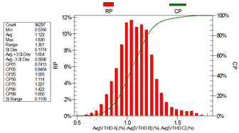
Fig. 3. Statistical analysis of harmonic voltage distortion measurements
V. Voltage Variation Ride Through
In the U.S. a common requirement is now for Zero Voltage Ride Through (ZVRT) for a three-phase fault for 9 cycles (0.15sec), however these requirements are relaxed for turbines installed before 2008, requiring LVRT to 0.15pu voltage for 9 cycles [6]. Some regions have also begun to adopt overvoltage ride through recommendations for turbine wind plants.
Solar plants are only now becoming large enough to be challenged to meet voltage variation ride through requirements. Traditionally, the smaller systems utilized inverter controls that would idle at the first instance of a system disturbance to prevent islanding. Large scale plants will require new inverter control systems that enable operation during voltage sags and swells.
VI. Flicker Requirements
Flicker is a variation in the system ac voltage, which can result in observable changes in light output and in some cases become annoying and objectionable. In a solar plant the important cause of flicker is a cloud that can cause an abrupt change in the irradiance and power output of the facility. In a wind farm flicker is caused by variations in wind turbine generator (WTG) power output due to variation in wind speed, blade pitching, tower shadowing, wind shear or gradient, and WTG start and stop operations.
The IEEE Std 1453 [7] has essentially adopted the IEC 61000-4-15 [8] to provide uniformity to internationally standards. While the methodology is uniform to the international measurements practice, the results will be comparable to the old “GE Curve” contained in the IEEE Std 141 [9].
Flicker is only a concern for interconnections to “weak” systems, such as distribution interconnections in areas of the system where fault currents are very low. The Utility Wind Integration Group (UWIG) has documented this phenomenon very well for wind facilities [10].
VII. IEC Guidelines
The IEC 61400-21 [11] provides manufactures practices for the measurement and specification of the power quality characteristics of turbine equipment. A companion document, the IEC 61400-22 [12] provide commissioning agencies practices for conformity evaluations on site installations.
VIII. Conclusion
This paper has an overview of power quality standards for wind and solar power plants. With the exception of some recent standards such as the IEEE Std 1547, IEC 61400-21, and IEC61400-22, most of the standards were generally not written with consideration given to renewable energy plants. Therefore, the standards need to be applied with consideration given to the newer challenges of these technologies. Also, new applications guidelines need to be developed.
Within the IEEE PES is the Integration of Renewable Energy into the Transmission and Distribution Grids Subcommittee. http://grouper.ieee.org/groups/td/renew/
In particular, the IEEE Working Group on System Impacts and Interconnection Requirements of Wind and Solar Power Plants is currently active in this important work. The working group is tackling a variety of issues and it always welcomes interested parties who can help formulate practices and standards. To participate in this working group’s activities, please see: http://grouper.ieee.org/groups/td/interconnect/
IX. References
- “Development and Validation of WECC Variable Speed Wind Turbine Dynamic Models for Grid Integration Studies”, M. Behnke, A. Ellis, Y. Kazachkov, T. McCoy, E. Muljadi, W. Price, J. Sanchez-Gasca, AWEA Windpower 2007.
- Characteristics of Wind Turbine Generators for Wind Power Plants, IEEE PES Wind Plant Collector System Design WG, IEEE PES General Meeting, Calgary 2009.
- IEEE Std 519-1992, “Recommended Practices and Requirements for Harmonic Control in Electric Power Systems”.
- IEEE 1547-2003 “Standard for Interconnecting Distributed Resources with Electric Power Systems”.
- IEC 61000-4-30:2008 Electromagnetic compatibility (EMC) – Part 4-30: Testing and measurement techniques – Power quality measurement methods.
- FERC Order no. 661-A, “Interconnection for Wind Energy,” Docket No. RM05-4-001, December 2005.
- IEEE 1453-2004 “IEEE Recommended Practice for Measurement and Limits of Voltage Flicker on AC Power Systems”.
- IEC 61000-4-15:2010, Electromagnetic compatibility (EMC) – Testing and measurement techniques — Flicker meter – functional and design specifications
- IEEE 141-1993 “IEEE Recommended Practice for Electric Power Distribution for Industrial Plants”.
- T.E. McDermott, “Distributed Wind Evaluation Methodology,” AWEA WindPower 2009.
- IEC 61400-21:2008 Wind turbines – Part 21: Measurement and assessment of power quality characteristics of grid connected wind turbines.
- IEC 61400-22:2010 Wind turbines – Part 22: Conformity testing and certification

Your style is unique compared to other folks I have read stuff from. Thank you for posting when you’ve got the opportunity, Guess I will just book mark this site.
LikeLike
Howdy I am so happy I found your web site, I really found you by accident, while I was searching on Aol for something else, Nonetheless I am here now and would just like to say kudos for a incredible post and a all round thrilling blog (I also love the theme/design), I don’t have time to browse it all at the minute but I have saved it and also added your RSS feeds, so when I have time I will be back to read much more, Please do keep up the awesome job.
LikeLike