White Paper, April 2013
Contributed by Chris Mullins, VP of Engineering and Operations, Power Monitors, Inc.
Email: cmullins@powermonitors.com
Website: www.powermonitors.com
Tel: 800.296.4120
ABSTRACT
Interharmonics are frequency components at noninteger harmonics of the line frequency. The proliferation of large DC-converter variable speed drives and wind/solar inverter generation has led to an increase in interharmonic levels. Troubleshooting the resulting problems requires measurements and terminology that go beyond “simple” harmonics. This
whitepaper covers the definitions and meaning behind the terminology for interharmonics, as defined by the IEC 61000-4-7 standard.
DEFINITION
By definition, if each cycle of a distorted waveform is identical, then there can be only integer harmonics of the fundamental frequency present. To be identical every cycle, each frequency component must go through an integer multiple of repetitions in a single cycle; otherwise, there would be a fractional bit left over at the end of a cycle, and the succeeding cycle would be different.
Unfortunately, many loads are not simple nonlinear systems, and frequency components that are not multiples of the line frequency may be present. There are several mechanisms that can cause this:
1.Direct injection of non-synchronous signals – e.g. power line carrier or mains signaling systems, where the injected voltage or current isn’t related to the 60Hz line frequency
2.Mechanical vibration of large motors, pumps, etc., where the vibration is translated electrically as a variation in load current or back EMF. If the motor is a VFD which already has harmonics, mechanical vibration can modulate each harmonic, resulting in interharmonics around each harmonic.
3.Beating and other interference effects from an AC->DC->AC system, or where two different AC systems are combined. Again, VFDs are a culprit , where the DC bus voltage is converted to a varying motor drive frequency. Interties to inverter-based generation from solar or wind farms can also be a source of interharmonics.
4.Non-synchronous loads such as arc welders where the instantaneous impedance is time varying in ways unrelated to the driving AC voltage.
To characterize this wide set of possibilities, IEC 61000-4-7 defines a standard method of measuring the frequency spectrum of the voltage and current signals. The spectrum is divided in to 5 Hz bands, and the magnitude of each component is computed over a 12 cycle sampling window (60Hz / 5Hz = 12. Any frequency that’s a multiple of 5Hz will have an integer number of period in a 12 cycle window). Thus, every block of 12 cycles is decomposed into a summation of sine waves with frequencies at 60Hz, 65Hz, 70Hz, 75Hz, etc. up until the highest frequency measured (3115 Hz with most recorders that measure to the 51st harmonic). Every 12th frequency is a multiple of 60Hz, and is technically not an interharmonic– 120Hz, 180Hz, etc. are the 2nd, 3rd, etc. harmonics.
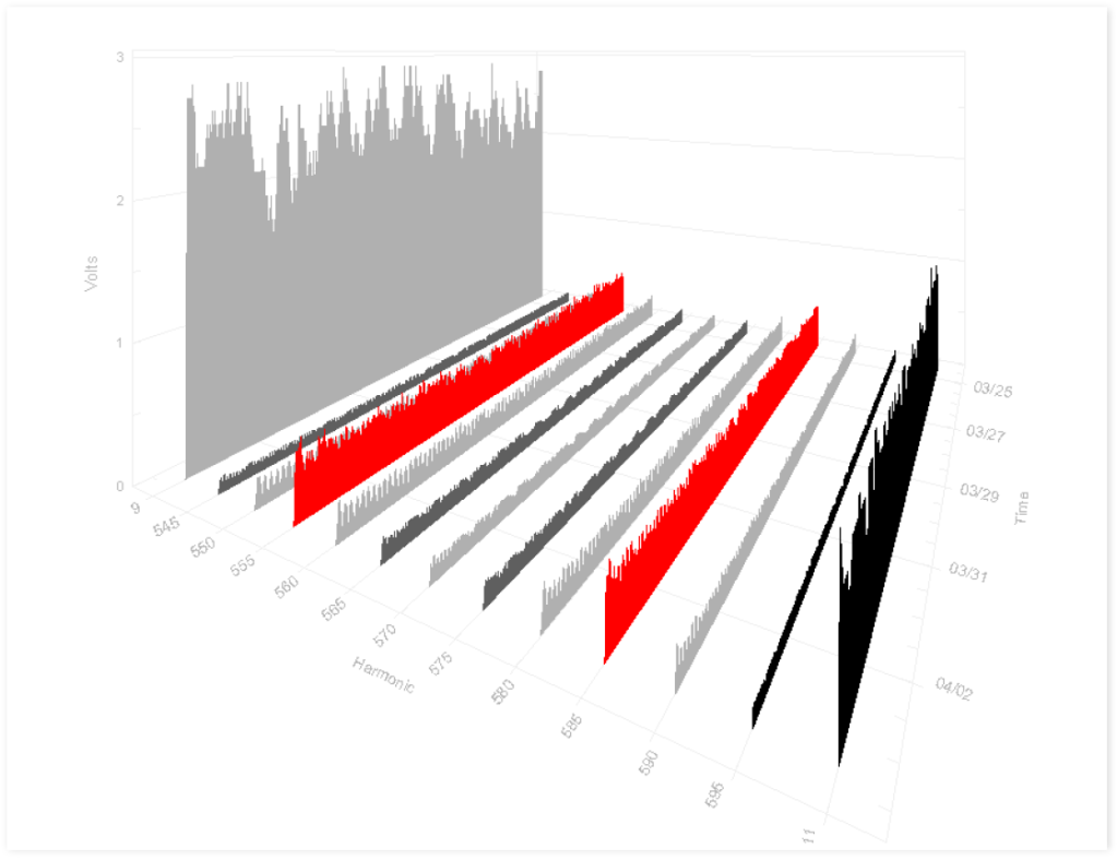
Figure 1. Powerline carrier meter reading system operates at 555Hz and 585Hz– right at two interharmonic frequencies (highlighted in red).
If there are no interharmonics present in the waveform, each of the 12 cycles will be identical, and only the fundamental and possibly the harmonics will be nonzero. If interharmonics are caused by injection of power line carrier signals or other narrowband sources, only the interharmonics at those frequencies will be non-zero. For example, a popular powerline carrier meter reading system operates at 555Hz and 585Hz (between the 9th and 10th harmonics), right at two interharmonic frequencies. They are clearly visible in the interharmonic graph of Figure 1 (highlighted in red), and are much lower in amplitude than the 9th or 11th harmonics, but higher than any interharmonics between those harmonics.
IEC 61000-4-7 defines the raw interharmonics as the frequency components every 5Hz, excepting the integer multiples of 60Hz (which are harmonics, not interharmonics). It goes further to define harmonic and interharmonic groups and subgroups. These are combinations of harmonics and interharmonics. Groups are used to aggregate harmonics and interharmonics to avoid recording hundreds of separate frequencies when not needed, and subgroups are used as refined aggregations.
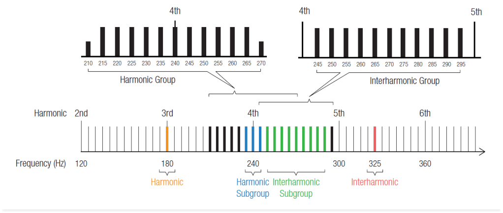
Figure 2. Groups and subgroups
HARMONIC GROUPS
A harmonic group is a combination of a specific harmonic and the surrounding interharmonics. There is a harmonic group for each harmonic. In Figure 2, the harmonic group for the 4th harmonic (240Hz) is shown. The 6 interharmonics to the left and 6 interharmonics to the right of 240Hz are combined with the harmonic itself with an RMS summation. This gives an aggregate RMS value for all components in that 60Hz-wide band centered around the 4th harmonic. (Technically, the outermost interharmonics – 210Hz and 270Hz in this case, are divided in half before summing, to avoid double-counting them with adjacent harmonic groups.) The harmonic group value represents the total signal in that entire region, and corresponds to the “regular” harmonic value for a system that computes harmonics with just a single cycle of the waveform (e.g. ProVision when it performs a harmonic analysis on a selected cycle of waveform capture data).
Harmonic groups provide a well-defined means for measuring frequency content with 60Hz resolution when finer detail isn’t needed. If no interharmonics are recorded, it’s better to use harmonic groups vs. raw 5Hz-wide harmonics, to avoid missing content outside the harmonic bands. If the interharmonics are low, then the harmonic group values will be the same as the raw harmonic values.
INTERHARMONIC GROUPS
An interharmonic group is a combination of all interharmonic values between two specific harmonics. The top right of Figure 2 shows the interharmonic group between the 4th and 5th harmonic. The RMS sum of all 11 interharmonics gives the interharmonic group value. Interharmonic groups are normally referenced by the harmonic to the “left” in the spectrum, so this would be the 4th interharmonic group.
Interharmonic groups are useful for recordings where interharmonics are suspected, but it’s not practical to record every possible 5Hz band. By using interharmonic groups, only 51 values are recorded for each channel instead of 51×12 = 612 values. Often the specific interharmonic frequency isn’t important (or isn’t even constant), so 5Hz resolution may not be needed. The key factor is that the harmonic spectral lines are excluded from the group, so the reading is only from interharmonic energy.
HARMONIC SUBGROUPS
Harmonic subgroups are formed by taking the RMS sum of a harmonic and the adjacent interharmonics. In Figure 2, the 4th harmonic subgroup is shown as the combination of the 235Hz, 240Hz, and 245Hz components. Harmonic subgroups are useful when the interharmonic cause is a modulation of the main current waveform. For example, a large VFD may produce harmonics due to rectification of the input voltage to a DC bus. If the motor load were constant, only harmonics would likely be present. Vibration due to mechanical imbalance can cause variations in the load current, and in the time domain this causes successive cycles of the current waveform to differ. In the frequency domain, the harmonic values are modulated, or “smeared” into wider bands. In cases like this, the two interharmonics on either side of the main harmonic are closely related to the physical phenomenon causing the harmonic, and they can be considered sidebands of the harmonic rather than separate signals. This gives a 15Hz wide harmonic band.
Harmonic subgroups are often used in place of the raw narrow-band harmonics when a distinction between harmonic and interharmonic values are needed, but the 5Hz spacing is too narrow to properly measure the true harmonic values. If there’s no need to separate out the interharmonics, then full harmonic groups could be used instead of subgroups – they include a full 60Hz wide band, vs. the 15Hz harmonic group band.
INTERHAMRONICS SUBGROUPS
Finally interharmonic subgroups are defined as the RMS sum of the 9 interharmonics between to specific harmonics, not including the two interharmonics immediately adjacent to the harmonics. Figure 2 shows the interharmonic subgroup for the 4th harmonic – it skips 245Hz, and includes 250Hz through 290Hz, skipping 295Hz. The interharmonic subgroup is the complement to the harmonic subgroup – it includes only those interharmonics not present in the harmonic subgroup. If the harmonics are modulated or spread into a band wider than 5Hz, and interharmonic aggregations are needed, use interharmonic subgroups instead of full interharmonic groups. Doing so avoids counting what’s really a harmonic value into the interharmonic group.
RECORDING INTERHARMONICS
There’s usually no need to record interharmonic and harmonic groups and subgroups at the same time. In theory every individual 5Hz interharmonic and harmonic can be recorded, and all groupings could be made later, but recording over 600 values per channel often isn’t practical. In order of increasing detail (and higher memory usage), here’s a suggested progression for recording setup:
1.THD only – provides no breakdown on harmonic content, but can reveal if distortion may be a problem
2.Harmonic groups – 60Hz-spaced bands, useful for determining spectrum of distortion, no distinction between harmonics and interharmonics.
3.Harmonic subgroups + interharmonic subgroups (or harmonics plus interharmonic groups) – provides detail on harmonic vs. interharmonic sources
4.Raw harmonics + interharmonics – full 5Hz resolution throughout band of interest – provides maximum detail, but uses the most memory. If the region of interest has been narrowed down (e.g. between 3rd and 7th harmonics), memory requirements are lessened.
CONCLUSION
IEC 61000-4-7 defines a method for calculating harmonics and interharmonics based on a 12 cycle window, and then further defines several aggregations of those values. The groups are used to consolidate harmonics back into 60Hz wide bands, and interharmonics into 55 Hz wide bands without any finer detail, for rough characterizations. The subgroups are used to provide a wider band for harmonics, accounting for modulation due to load and system variations, and to avoid including harmonic sidelobes into interharmonic data. An understanding of these groupings is important for maximizing recorder memory, and avoiding having too much detail to analyze.

Good post. I learn something totally new and challenging on blogs I stumbleupon on a daily basis. It will always be exciting to read content from other writers and use a little something from other sites.
LikeLike
Hey! I’m at work browsing your blog from my new iphone! Just wanted to say I love reading through your blog and look forward to all your posts! Keep up the excellent work!
LikeLike