Published by
- Ahmed F. Zobaa and Ibrahim Ahmed, Department of Electronic and Computer Engineering, Brunel University London, Uxbridge, UB8 3PH, UK.
- Shady H.E. Abdel Aleem, Mathematical and Physical Sciences, 15th of May Higher Institute of Engineering, Cairo, Egypt.
Journal Article:
Recent Advances in Electrical & Electronic Engineering, 2019, 12, 210-222 (Volume 12, Issue 3 ,2019) , Published on 10 June 2019
Abstract: Background: Renewable energy generation using wind energy has emerged worldwide and has opened up significant new markets in electrical power generation. However, different factors that affect power quality performance of Wind Turbine (WT) applications such as wind speed fluctuation and use of power electronic based devices have been presented due to the rapid increase of WT installations.
Methods: Accordingly, it is worth to measure, assess and evaluate the quality of the generated power of these WTs in order to ensure their compliance with the grid-integration conditions. In this work, first, a general classification of WTs and their operating principle is reviewed. Because variable speed WTs are frequently used in today’s power systems, much attention was paid to this type of turbines. Second, the various power quality aspects caused due to the integration of the wind energy systems into the grid were presented and discussed. Flickers, harmonic distortion, response to voltage dip, active power, and reactive power requirements, fault-ride through and short-circuit current contribution were the addressed power quality problems.
Results: Further, the study pointed out the need for a unified evaluation process to assess the power quality performance of the grid-connected wind systems.
Conclusion: Also, it was concluded that success in integrating more wind energy systems hinges on accurate power quality performance assessment.
Keywords: Active power control, fault-ride through, flicker, harmonic distortion, reactive power control, renewable energy, power quality, wind turbines.
INTRODUCTION
Recently, the public debates carried out a lot of stress on the traditional energy generation technologies that rely on fossil fuel sources. In the conventional electrical power generation, CO2 is usually released, which has a detrimental effect on global warming. In addition, electrical energy demand is rapidly increasing worldwide, keeping in mind the limited fossil fuel resources. Consequently, the need for renewable and sustainable energy resources such as wind, solar, tidal, and wave has been noticeably increased in recent years [1-7]. Wind has been known as a source of energy long time ago. The ancient Egyptians utilized the wind power around 5000 BC [8]. Nowadays, wind power is considered as one of the most convenient green power sources because of its availability, efficiency, and environmental-friendly performance. Wind energy releases only 20% of the corresponding natural gas emissions of CO2E/kWh [9, 10].
In its early stages, wind turbines (WT) were coupled directly to the grid and operated in a very narrow speed range, so-called fixed speed turbines. Modern WTs have a wide operating speed range with the aid of power electronic interfaces, and these types are known as variable speed WTs.
The installation of wind power plants is rapidly increasing worldwide. In 2016, the total installed wind power capacity was about 456 GW [11, 12]. However, renewables, in general, suffer from unavailability sometimes as well as the intermittent because wind speeds and directions are continuously changing by nature. This intermittent nature of wind causes fluctuations in the output shaft power of the WT at the Point of Common Coupling (PCC) which may lead to various Power Quality (PQ) problems such as voltage flickers and others [13-16]. Similarly, the use of power electronic converters in modern WTs introduces extra PQ problems such as harmonic distortion, voltage imbalance, and voltage fluctuations [16-19]. Hence, it is essential to evaluate the PQ impacts of the grid-connected WTs to ensure safe and reliable operation of the electrical networks to allow much more potential of WT projects. In this regard, PQ measures of a WT are usually performed and evaluated at the PCC. Several guidelines were established to evaluate PQ performance of WTs such as IEC 61400-21 [17].
In this work, first, a general classification of WTs and their operating principle is reviewed. Because variable speed WTs are frequently used in today’s power systems [20], much attention was paid to this type of turbines. Second, the various PQ aspects caused due to the integration of the wind energy systems into the grid were presented and discussed.
Flickers, harmonic distortion, response to voltage dip, active power, and reactive power requirements, fault-ride through and short-circuit current contribution were the addressed PQ problems. The rest of the paper is organized as follows: Section 2 explores the various types of WTs. Design and construction of variable speed wind turbines are presented in Section 3. The various requirements and PQ issues of grid-connected WTs are investigated in Section 4 and finally, Section 5 presents the conclusions and findings of this study.
MATERIALS AND METHODS
Classification of Wind Turbines
Classification of WTs can be done on the basis of their structure such as turbines designed to use gearboxes or directly driven without gearboxes (gearless). Also, they can be classified by speed as fixed, partial-variable or variable speed turbines. Some can categorize the turbines by the power control used (stall, pitch control, or active stall). The orientation of the spin axis (vertical or horizontal or even bladeless) is another way of classification. In addition, WTs may be classified according to size (small, medium, or large) and installation location (onshore and offshore) [21-24].
In practice, todays’ WTs have four principal types (A, B, C and D) based on the speed range, in which Type A is a fixed speed WT that is equipped with an IG. Type B is a limited variable speed turbine with an IG and variable rotor resistors. Type C is a doubly-fed IG (DFIG) that is equipped with a partial-power converter. Lastly, Type D is a variable speed WT that is equipped with a PMSG and a full-scale power converter. To date, the wound rotor synchronous generator and the squirrel-cage IG are used with Type D turbines. Type A was the first WT generation, where the squirrel cage IG windings are coupled to the utility grid directly. The turbine’s rotor shaft is coupled via a gearbox to the turbine shaft. Stall control is usually adopted in this type to control the blades during high wind speeds. The configuration of this WT is illustrated in Fig. (1a). On one hand, the advantages of this type are its simplicity, rigidity, and low cost. On the other hand, its poor efficiency, the absence of controllability of power and its restricted speed, i.e. 2% of the rated speed, are the major drawbacks of this type. In addition, this type requires a capacitor bank to compensate for reactive power that is absorbed by the induction machine. Considering all these disadvantages, Type A is no longer a choice for today’s WTs installation [21, 22].
Likewise, turbines of Type B are comparable to those of Type A except that a wound-rotor induction machine is to be used instead of the squirrel-cage one, i.e. the rotor windings are shortened by variable speed resistances as shown in Fig. (1b). The advantage of Type B is the extended speed of operation (10% of the rated speed), whereas a greater capacitance size will be necessary as the losses will increase because of the resistances and reactive power support will be needed [25].
Type C is equipped with wound-rotor IG as shown in Fig. (1c), where the stator terminals are connected directly to the grid similarly to the previous types. However, the rotor windings are coupled by a fully-controlled converter to the grid, which enables a wide operating speed range ( ± 30 of rated speed) [26]. RSC stands for the rotor-side converter while the GSC is the grid-side one. A pitch angle scheme controls the blades. This type is the most widely used among all the WT types because of its wide range of speed, optimal power extraction from the wind, and low mechanical stress on the rotating parts (compared to Types A and B). However, the configuration of Type C demands further protection for the converter in case of faults [27].
Lastly, in Type D, a full-power converter is needed to transfer all the turbine power to the grid. Induction or synchronous generators can be used with this type, where both the wound rotor and permanent magnet can be useful in case of a synchronous generator, and currently, the PMSG outperforms the other machines because of its simple construction and elimination of DC excitation. The PMSG can be constructed with a large number of poles; however, this gives the advantage of operating directly without the need for gearboxes. Type D is equipped with a direct-driven PMSG as shown in Fig. (1d), where it can be noticed that the generator terminals are coupled to the converter and all the WT power will flow through the converter. This is why it is commonly realized that the converter size must be rated equal to (or slightly above) the nominal power of the WT.
Also, the blades are controlled by a pitch angle control, and the converter regulates the active and reactive power control of this scheme, and the turbine can then operate with a wider speed range. However, its main disadvantage is the high cost [28, 29].
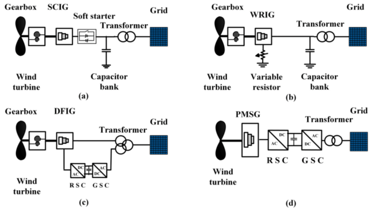
Fig. (1). Types of wind turbines.
MODERN VARIABLE SPEED WIND TURBINE
The kinetic energy stored in the moving air is converted to mechanical energy through the WT blades, and then this mechanical energy generated at the WT’s shaft is converted into electrical energy through the electrical generator of the WT. The variable speed wind turbines (VSWT) can produce electricity at a wider range of speeds, even at lower speeds below the synchronous speed. This wide operating range makes the VSWT outperform the conventional fixed speed WTs. Modern VSWTs contain complicated power electronic converters and advanced control systems such as pitch angle control which are employed to protect the blades from overspeed mechanical problems during high wind speed conditions [30-32].
Aerodynamic Power
The mechanical power generated by a multi-blade WT is defined by Betz law as expressed in Eq. (1): The output power (Pm) supplied from the wind turbine is given as follows [33, 34]:

where, “ρ is the air density, A is the rotor swept area, v is the wind speed, and Cp (λ, β) is the power coefficient as a function of the tip-speed ratio λ and the pitch angle β”. It should be mentioned that the Cp is the most important parameter in power regulation [35]. Look-up tables from turbine manufacturers are provided to indicate the Cp for operation turbine operations. Also, different models for Cp have been developed [36] as a function of λ and β. For example, for particular turbine types, Cp is given as follows:
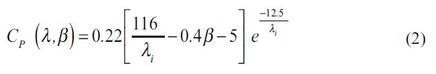
In which, the parameter λi is defined in terms of λ and β as follows:

where β is the angle between the plane of rotation and the blade cross section chord and λ is the tip-speed ratio of the turbine. The relation between λ and Cp when β equals zero is given in Fig. (2). It is noticed that the optimum Cp is achieved when λ varies between 6.1 and 6.5 which ensures maintaining maximum power point tracking within this operational range.
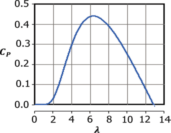
Fig. (2). Power coefficient for different tip-speed ratios.
Operation of Variable Speed Wind Turbines
A VSWT that operates at low wind speed guarantees that the optimum value of power is captured from the cut-in till rated speed, by keeping Cp at its maximum value. Every wind speed has optimum power point which is obtained at specific rotor speed. Fig. (3) shows an example of the output power of a VSWT power at different wind speeds and turbine rotor speeds, where the pitch angle is kept equal to zero. The maximum power available at a WT can be gained by an algorithm or a locked-table utilizing the converter support for power regulation.

Fig. (3). Turbine power at different wind and rotor speeds.
At high wind speed condition, the WT aerodynamic power increases, causing an increase in rotational speed too. Pitch control system is employed to limit the aerodynamic power to avoid rotor over-speed that may lead to a mechanical system failure. The blades’ pitch angle is regulated to decrease the power coefficient, so the extracted power is limited to the WT nominal power [31].
Wind Turbine Parts
WTs system consists of various parts. The WT system has three main parts outlined as follows [37, 38]:
- The mechanical part: the mechanical part consists of the pitch control mechanism, gearbox, and driver train.
- The electrical part: the electrical part usually consists of the electric generator, power electronics devices including the converter, capacitance and inductance components, and protection system including the crowbar, braking resistor and circuit breaker, transformer, and interconnecting cables.
- The control system: the converter controller and blade angle control are included in this system.
GRID-CONNECTED WIND TURBINES: REQUIREMENTS AND POWER QUALITY
If the voltage and current are continuous and have a pure sinusoidal wave with a constant frequency and amplitude, this would be perfect ‘ideal’ PQ case. Nowadays, the terminology of PQ is commonly used in recent power systems due to the unprecedented development of the power electronic interface technologies and renewable energy resources under the umbrella of smart grids. To-date, there is no typical and unified definition for the PQ [33].
Without a doubt, PQ has dissimilar interpretations for parties in different electric entities. For instance, PQ is used sometimes to express the quality of voltage, while others use it for the quality of current, and some use it to define the service reliability. Moreover, it can be used to express the electricity quality in the electrical energy markets. Excessive utilization of recent power-electronic devices and the increasing integration of renewable energy resources with their inverter-based interfaces into distribution systems have brought different PQ problems with these systems [39].
PQ can be defined as a terminology that describes maintaining the near sinusoidal waveform of power distribution node voltages and line currents at rated operating conditions. Generally, voltage quality focuses on variations of the voltage from the ideal waveform (that is characterized by a sine wave of constant magnitude and frequency). Therefore, PQ can be defined as a set of electrical limitations (reference limits) that enables an equipment to operate in its planned manner without major operating losses or lifetime deteriorations [40].
The main PQ problems associated with the excessive penetration of WTs are harmonic distortion, voltage imbalance, and voltage fluctuations and flickers. As a result, precautionary measures need to be defined through which the lowest acceptable level of power quality could be guaranteed besides ensuring the right behavior of the equipment that is fed from the power distribution system [41]. The past years have witnessed a rapid increase in the installation of wind power units and other distributed generation units. In fact, the riskiest source of energy is believed to be the wind energy with respect to PQ. When the grid involves WTs, PQ becomes a multifarious issue which greatly relies on the interface technology between the wind turbines and the grid [41- 44]. In order to cover WT impacts on PQ, several guidelines were published; such as the IEC 61400-21 [17].
This section provides a comprehensive review of the various PQ issues associated with the grid-integrated WTs and their inter-connection measures.
Flicker
One of the significant characteristics regarding PQ in wind energy is the voltage flicker [45]. Basically, voltage flickers are defined as a continuous rapid variation of input supply voltage sustained for an appropriate period to enable visual recognition of a variation in electric light intensity. Flicker is a PQ problem in which the magnitude of the voltage or frequency changes at such a rate so as to be noticeable to the human eye [39, 46].
Regarding the wind energy systems, the rapid change in wind speed, wind shear, yaw error, and tower shadow may cause a variation in the output power that results in voltage fluctuations at the PCC which sequentially generate flickers [10, 42]. The flicker severity is assessed over a short period (usually 10 min) is known as Pst, and that evaluated over a longer period of time (two hours) is known as Plt. Thus, Plt is a combination of twelve Pst values. Calculation of Pst is commonly expressed as given by Eq. (4) [33, 47]:
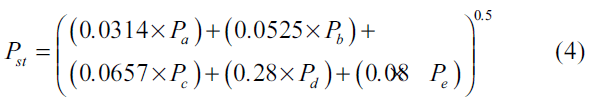
where Pa, Pb, Pc, Pd, and Pe are the surpassed flicker levels during 0.1, 1, 3, 10 and 50% of the surveillance period. By definition, value of one for Pst expresses a visible disturbance, a level of optical severity at which 50% of persons might sense a flicker in a 60 W incandescent lamp. Excessive light flicker can cause severe headache and can lead to the so-called ‘sick building syndrome’ [48].
The critical value of irritability is set at Pst = 1, magnitude of the maximum acceptable voltage change in relevance to voltage changes per minute is illustrated in Fig. (4) [49]. It is hard to measure the flicker accurately, and for this purpose, IEC Standard 61000-4-15 developed a device called ‘flickermeter’ to calculate the functional specifications of flicker [50].

Fig. (4). The IEC curve for Pst =1 for different voltage changes [49].
IEC 61400-21 [17] specifies a measurement procedure to determine the flickers emitted from WTs. Moreover, the representation of the flicker for two different situations namely, switching and continuous operation is defined. In the continuous operation, the flicker resulted from active and reactive power fluctuation; IEC 61400-21 requires a statistical calculation for the so-called flicker coefficient C(![]() k, va) which is defined as: “A normalized measure of the maximum flicker emission (99th percentile) during continuous operation of a WT”. C(
k, va) which is defined as: “A normalized measure of the maximum flicker emission (99th percentile) during continuous operation of a WT”. C(![]() k, va) is determined at each 6, 7.5, 8.5 and 10 m/s of wind speed and network impedance angles: 30°, 50°, 70° and 85°. C(
k, va) is determined at each 6, 7.5, 8.5 and 10 m/s of wind speed and network impedance angles: 30°, 50°, 70° and 85°. C(![]() k, va) is calculated as follows:
k, va) is calculated as follows:
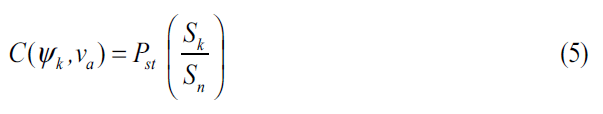
It should be mentioned that ![]() k stands for the network impedance phase angle at the PCC, and va stands for the annual average wind speed at the hub-height of the wind turbine [42]. Also, Sk is the short-circuit capacity of the grid where the WTs are connected. Sn is the WT’s nominal power. In a switched mode of operation of a WT, flickers occur by power fluctuations at the start or the stop operations of the turbines. Based on IEC 61400-21 [17], two indices should be measured during a switching operation, namely kf(
k stands for the network impedance phase angle at the PCC, and va stands for the annual average wind speed at the hub-height of the wind turbine [42]. Also, Sk is the short-circuit capacity of the grid where the WTs are connected. Sn is the WT’s nominal power. In a switched mode of operation of a WT, flickers occur by power fluctuations at the start or the stop operations of the turbines. Based on IEC 61400-21 [17], two indices should be measured during a switching operation, namely kf(![]() k) which is standardized flicker emission data of a single switching process, and ku(
k) which is standardized flicker emission data of a single switching process, and ku(![]() k) which is a standardized measure of the change in voltage as a result of the switching action. IEC 61400-21 [17] states that kf (
k) which is a standardized measure of the change in voltage as a result of the switching action. IEC 61400-21 [17] states that kf (![]() k) and ku(
k) and ku(![]() k) should be measured at different angles as 30°, 50°, 70° and 85°. kf (
k) should be measured at different angles as 30°, 50°, 70° and 85°. kf (![]() k) and ku(
k) and ku(![]() k) are calculated as follows:
k) are calculated as follows:
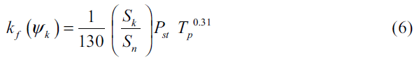

where Umax and Umin are at the maximum and minimum root-mean-square (rms) phase-to neutral voltages, respectively. Un is the nominal phase-to-phase voltage. Tp is the transient time period of a switching operation. The WT manufacturers usually perform factory tests on WTs to evaluate the performance and PQ related emissions of each WT. The level of flicker varies from turbine type to another. The variable speed WTs produce lower flicker compared to the fixed speed WTs [10]. This is due to the controllability of variable speed WTs, which absorb the power fluctuations and therefore mitigate flickers [51-53].
Several factors affecting the flicker in VSWTs and they are directly related to the rise in wind speed until the rated value which occurs when the WT reaches its maximum power. When the wind speed increases beyond its rated value, the pitch control will smooth out the variation in output, thus flicker will be reduced consequently [54, 55].
Besides, the flicker emission is significantly influenced by the short-circuit capacity of the connected network at the PCC. A WT usually produces greater flickers in weak grids as the flicker level has an inverse relationship to the short circuit capacity [55].
The flicker emissions of WTs are considerably affected by the wind turbulence intensity, such that the flicker level increases with the increase in the wind turbulence intensity [55]. The grid impedance angle also plays a significant factor that affects the flicker levels. Lower flickers occur when the difference angle between WT power factor and the grid impedance angle reaches 90°. As VSWTs have the ability to control reactive power; flicker can be mitigated by regulating it [22]. Lastly, in the comparison between VSWT types, DFIG has fewer flickers in continuous operation, whereas PMSG has considerably lower values of kf(![]() k) and ku(
k) and ku(![]() k) in the switching operation [56].
k) in the switching operation [56].
Harmonic Distortion
Power system harmonics are defined as multiple integer frequencies of the fundamental system frequency (typically 50 or 60 Hz) presented in electrical voltage or current waveforms. Power system harmonics result from various types of harmonic generating equipment such as power-electronic converters, arc furnaces, fluorescent lamps, and other nonlinear loads. Harmonics can cause many problems such as parallel and series resonance, thermal overloading of lines and cables, overheating of transformers, nuisance operation of protection relays, which in turn decrease reliability and increase losses of power systems [57, 58].
The variable speed operation of WTs was made possible with the advancement of the power electronics integration technologies which inject a considerable amount of current harmonics into the electrical networks. Based on the guideline IEC 61400-21 [17], measurements of current harmonics are required only for VSWT, and the fixed speed WTs are to be excluded since they do not include power electronic converters whereby their current harmonic emissions can be neglected [10, 42]. The standard explicitly details certain processes to measure individual and total harmonic current distortion in terms of the rated current in percent (In%) and the bin midpoints for WT operation in the range of the active power levels 0, 10, 20, 30… 100 % of the nominal power (Pn). The generated harmonics shall be measured up to 50 times of the nominal frequency in addition to the interharmonics up to 2 kHz based on the IEC standard 61000 4-7 [59], and for the higher frequency range from 2 kHz to 9 kHz. The measurement process shall be performed at steady state operation and no reactive power production. However, the standard does not consider short-duration harmonics produced during switching operations because these harmonics last for small-time periods.
The total harmonic current distortion (THDC) is determined in terms of the hth harmonic current and the fundamental harmonic one (I1) as follows:

IEC 61400-21 [17] does not claim any limitation for the current harmonic; instead, several standards can be applied to assess the current harmonics such as IEC 61000-3-6, IEEE 519-2014, and EN 50160 [60-62]. The low order harmonic frequencies, i.e. 3rd, 5th, 7th and 11th are the most dominant current harmonics in VSWTs due to the control system and the PWM switching control [63, 64].
The harmonic distortion in VSWTs depends on several factors such as the type of the control system (PWM or hysteresis), converter topology (voltage or current source inverter), harmonic filter and the type of VSWT (DFIG or PMSG). Harmonic distortion appears on both the stator and rotor currents in DFIGs [65-67].
The harmonics and inter-harmonics in DFIG WTs are produced by GSC, RSC and the WT itself. The total induced harmonics in DFIG that are caused by both converters and the machine itself are expressed in details in [68] as follows:
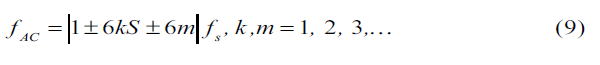
where fAC represents the harmonic frequencies at the AC converter’s sides. S is the generator slip and fs is the stator frequency. The DFIG harmonic emission is also affected by the background supply harmonics [69]. The harmonics of lower order are the dominated ones in DFIG current harmonics, and the values of the 5th and 7th harmonics are relatively high and the THDc will be high when the output current is considerably low [70, 71]. DFIG has higher THDc when compared to PMSG WT, due to the presence of interharmonics [22, 72]. When the PMSGs are being considered; the GSC is responsible for the generation of harmonics. The GSC is typically a six-pulse inverter. The harmonic and inter- harmonic currents can be linked back to the operation of power electronic switching devices.
The generated current of PMSG contains low order harmonics such as the 3rd, 5th, and 7th where the 5th harmonic order is usually higher. The harmonics in PMSG depend on the converter topologies (current-source inverter or voltage source inverter), the converter structure (multilevel, two level or matrix), and the control strategy (hysteresis current control, space vector pulse width modulation or sinusoidal pulse width modulation).
Accordingly, one can notice that the electrical grid plays a vital role in the determination of the percentage of the voltage harmonic distortion at the PCC with WT plants by the variations that may occur in the grid impedance at the PCC. According to the common practice during the design stage of grid-integrated WT projects, the worst case of the grid impedance has to be considered while specifying the maximum allowed harmonic pollution [73] from a WT project.
Voltage Unbalance
Voltage unbalance (VU) is a PQ significant problem that can be explained as “a condition in a poly-phase system in which the rms values of the fundamental components of the line voltages, and/or the phase angles between consecutive line voltages, are not all equal” [74]. VU occurs in electrical power systems due to irregular distribution of single-phase loads over the three phases, single-phase distributed resources, power system faults, asymmetry of lines, and unbalanced power system faults, and others [75].
The expression of Voltage Unbalance Factor (VUF) presented in IEC Standard 60034-26 [76] is commonly used to represent the VU, where WTs should withstand VUF not exceeding 2%. VUF is given as follows:

where V– and V+ denote the phasors of the negative sequence and positive sequence voltage components, respectively.
Short-circuit Current Contribution
Every element in a distribution network such as cables, transformers, and switchgear has a particular designed short-circuit current (SCC) level to be withstood. This SCC can be defined as a measure of the maximum fault current expected for a particular element. Exceeding of the SCC limit of a certain element must be avoided to avoid excessive thermal damages to this element. SCC may cause an intolerable overload to the power system components (machines, transformers, cables, transmission lines, etc.). SCC can even lead to damage depending on the magnitude and duration of these components [77]. An adequately-designed protection system should detect and interrupt excessive SCCs to ensure safe and reliable operation of electrical networks.
Excessive penetration of WT plants leads to a noticeable increase in maximum SCCs in the network [78]. In addition, the intermittent nature of the output power generated by the WTs plants makes their contribution to the grid SCC currents more complex. The relation between the installed capacity of WT farms and the impact of large-scale WTs integration on the PQ performance is directly proportional. Simply, as the wind power increases, a higher SCC will be injected into the system. The effects of different types of WTs on the power grids greatly vary from one type to another. The SCC from DFIG-WT depends on the rotor’s circuit breaker protection settings on the RSC. In an instance where the rotor is short-circuited by a rotor circuit breaker; SCC features of the turbine act as the constant speed WT, a temporary inrush current takes place in the fault and vanishes quickly [79]. The maximum SCC of DFIG is calculated as follows [22, 80, 81]:
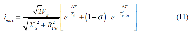
where imax is maximum rotor’s fault current, ΔT is the time of the first peak, Tr’ .CB is the transient time constant, Tr′ and TS′ are the stator’s and rotor’s transient time constants respectively, and RCB is the equivalent crowbar resistance. Under a condition that RCB >> Rr; Tr’ .CB is small, and the time when the first peak is formed is given as ΔT →0. In this situation, a simplified equation for DFIG maximum SCC can be derived as follows:
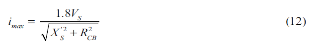
It can be deduced from (12) that a higher crowbar resistance may cause a less peak current; whereas a maximum crowbar resistance value (RCB,max) can be determined if the most permissible rotor-voltage is known. In case of PMSG, the SCC caused by the fault is restricted to the nominal current or just a bit greater than it. It is quite usual to design PMSG power converters to have an overload ability of 10% over their nominal rating. Keeping in mind that, in all kinds of faults, the generator remains connected to the converter and separated from the fault in the grid [82-84]. Therefore, even if there is a grid disturbance, the WT’s current is managed to maintain its acceptable limit, e.g. 1.1 per unit.
Response to Voltage Drops
The occurrence of voltage drops is considered as a specified issue for WTs behavior in power systems. These drops are random in nature and they are classified by their amplitudes and duration time. Past experiences had revealed that wind power generation is greatly affected due to these voltage drops and even in their recovery, if disconnected from the grid. IEC 61400-21 [17] comprises of certain offline tests that determine whether the system can survive these voltage drops and supports grid stability and to what extent precisely. This test is performed when the WT is disconnected from the grid, and consequently, it will not be requested to modify the voltage wave. The considered rated active power (Pn) of the WT is to be between 10% – 30% in the first scenario of the test and then above 90% in the second one, as observed in the test. Further, a number of different six voltage drops are defined in the test, while specifying the magnitude and duration of the rectangular voltage drop [85, 86].
The test is carried out by a simulation to set a fault by linking three or two phases to each other or linking three or two phases to the ground using impedance that is calculated to obtain the voltage magnitudes specified in the standard when the wind turbine is not connected to the grid. A short-circuit generates the voltage drops. The voltage drop testing must not end up in an undesirable condition at the upstream grid, and it must not considerably disturb the WT transient response. During a voltage dip, in the grid, the active power which can be injected is affected by this drop. Consequently, a surplus of the active power is experienced, and over-speed occurs as a result of the imbalance between the aerodynamic power and WT output power [87]. Under these conditions, WTs can get disconnected from the grid. The grid voltage can be improved if the WT can provide a reactive current.
As a comparison between the PSMG and DFIG operators in VSWTs, PSMG operates smoothly when it is subjected to the voltage dip issue and it supplies more reactive power [22, 88]. In PMSG-WT, the full-scale converter isolates the generator terminals from the grid, and the GRC controls the current up to a given reference value (which is usually set to 1.2 p.u.). Because of the active power reduction, a rise in the DC link occurs, and it might cause damage to the converter. For improving PMSG performance during the voltage dip, a crowbar can be used in the DC link to decrease the extra power and balance the power between the grid-side converter and generator-side converter. The voltage dips can greatly affect the DFIG as there is a direct coupling of the stator terminal to the grid. In the absence of a protection system, the transient in the stator current is very high at fault which can affect the DFIG. The transient (from stator) is transferred to the rotor as a result of the magnetic coupling which links the stator to the rotor. The transmitted transient causes higher voltage and currents in rotor windings under fault conditions. It is consequently essential to protect the converter from overcurrent, the rotor winding and the DC bus from overvoltage. The rotor crowbar method can be considered as a traditional solution to improve DFIG performance during voltage dips [89-93].
This is the main procedure that is followed by the majority of the manufacturers to manage fault ride through. Even though the crowbar is not an expensive way of protecting both the generator and the converter in fault conditions, there is one big issue in which DFIG loses the control after the initiation of the crowbar as a result of deactivation of the rotor-side converter [93]. The employment of pitch-angle control of WT system is to avoid the over-speed of the generators rotor which is accomplished by turning the blades to reduce the power coefficient of the WT. Lastly, it should be mentioned that the response of the pitch-angle control can be greatly restricted when a WT is connected to a weak grid because of the great dynamic power that would be caused from backing up the power throughout fault despite the fact that the pitch control mechanism can quickly turn the blades to their maximum values [94].
Voltage-ride Through
One of the major characteristics of wind power plant that has a considerable impact on power system networks is the voltage-ride through that is commonly recognized as FRT. Transmission System Operators (TSOs) in several nations are establishing grid connection requirements (grid codes) for the wind generators to ensure that the electric system is stable and has a sufficient amount of access to wind power, and they fulfil various technical needs, including the FRT, that means capacity of the WT system to stay steady and connected to the network in case of faults that may occur in a network [86, 95, 96]. Due to errors in the transmission systems, huge temporary voltage defects in a power system can be caused. The design of each power system is made in a way so that it can bear a large unexpected loss of a particular value of generation capacity and it can function accordingly. If a generation unit connects to the healthy grid, it loses connection and stability during or after a grid fault, and this generation is lost [96, 97]. It is evidently seen that the frequency of the system is reduced at a very fast rate in case of a huge loss of generation, and the need of load shedding arises to make sure that the system remains stable [98]. Previously, WTs had quite fewer needs regarding their functioning during a grid fault; they use cut off in the duration as per the voltage amplitude and fluctuations in the frequency. Currently, the needs for FRT demands the WTs to stay connected along with this in a few countries to support the grid and maintain the power systems’ stability. In particular, the WTs are obliged to remain connected to the grid after a fault on any or all phases for faults duration of specific periods that differ from one code to another, while specifying the minimum voltage level (percentage of the rated voltage) during the fault and the time to remain connected during the fault, whereas the maximum voltage dip duration is also specified. However, disconnection of WTs is permitted if the fault remained longer than the standard clearing time [10]. An example of voltage profiles for FRT of different grid codes in European countries is shown in Fig. (5) [97, 99].

Fig. (5). FRT profile for different grid codes [99].
In addition, the needs of grid codes for FRT capability of the WTs vary from one grid code to another, these needs also include the reactive power support, restoring active power, and short-circuit power and grid impedance angle aspects. A brief description of the grid codes of the countries mentioned in Fig. (5) is given as follows: The German code demands that the WT must inject reactive power when voltages dip 10% or more. Moreover, when the voltage is below 50%, the active power shall not be produced just reactive power [100]. The Spanish grid code states the requirement for reactive current in comparison to all current injected [101]. In the Irish grid code, despite remaining coupled to the grid, WTs are required to supply active power along with maximum reactive current [102]. For the Danish grid code, there is no demand for providing the reactive current; nevertheless, the grid code requires to study the WT performance during voltage dips [103]. The turbines behave in a different way for FRT according to their generator’s topologies, control, and protection.
RESULTS AND DISCUSSION
Furthermore, fixed speed WTs cannot support reactive power; as a result, these WTs are unable to meet most of the grid code. However, this problem can be avoided by applying external supporting devices such as FACTS, e.g. STATCOM and SVC [104, 105]. VSWTs can produce reactive power which improves the voltage during critical conditions. However, if the voltage dip is served like German grid code, DFIG can fail to provide the reactive power since the protection system blocks the DFIG due to the current limitation which leads to losing the controllability. On the other side, PMSG with full-scale converter has better flexible control; hence it can meet grid code demands [106, 107]. FRT can be enhanced for VSWTs several methods, e.g. a breaking resistor attached to the DC-bus, energy that can be stored in rotating masses in the form of inertia and by avoiding the operation of maximum power tracking during the faults.
Active Power Control
To ensure coordination between the various WT farms and the grid, the output active power of the WT farms should be controlled, based on the system loading and the grid operator requirements. Different active power regulation modes are required in WTs farms. The most common modes of control are the delta control, specific power limit, and balanced control. IEC 61000-21 and some grid codes require active power regulations (active power control modes) which are responsible for limiting the maximum active power, balancing the active power output, and defining the ramp rates upward or downward.
The frequency converter of the VSWT responds faster to the reference signals. When the fluctuation reduces through regulation of the generator, VSWTs can operate at the maximum power; therefore, efficiency and PQ will all improve. Standard IEC 61400-21 [17] tests the wind speed to check the WTs’ capability to regulate the active power. The test might include both the WT as well as its control system [86]. The three measurements regarding the active power are given, as follows:
- Maximum measured power: The maximum WT’s electrical power output over three averaging periods shall be reported as 0.2s, 60s, and 600s values.
- Ramp rate limitation: The WTs capability to conduct ramp rate-limitation control mode is specified by a test to show the available and measured active power output during operation at 10% ramp rate value of the rated power.
- Set-point control: The WTs ability to provide active power according to set-point control mode is conducted where a set-point value is to be changed from 100 % to 20% of the nominal power by 20% step every two minutes until 20% of rated power is achieved, then increased back to 100%. Fig. (6) illustrates the active power set-point test [86].
It can be noticed from Fig. (6) that the set-point control ensures that the output active power from the WT remains within its pre-set range of operation. The capabilities of a WT to participate in an automatic frequency control scheme are closely linked to its ability to produce active power based on set-point control mode. For example, the data acquisition system and supervisory control of a modern wind farm may regulate the active power set-point of a single WT constantly to attain a particular frequency response. Therefore, participation in an automatic frequency control can be done. In VSWTs, the maximum measured power is, P600 = P60 = P20 [86]. Moreover, VSWTs have the ability to track the active power signal very fast and can meet the IEC 61400 compliance easily [22, 108, 109]. However, it can be mentioned that a PMSG may show slightly faster performance as com pared to the DFIG because its power can be controlled by the inverter instantaneously.

Fig. (6). Active power and the set-point control [17].
Reactive Power Control
The early WTs were using IGs because they are low-cost, rugged, and simple machines that need less maintenance. In the early generation, WTs were lacking controllability of the reactive power, WTs were equipped with IGs that absorb reactive power, and a capacitor bank that is needed for compensating this consumed reactive power. In modern WTs, the use of power electronic converters allows for a full control decoupling between active and reactive power. Today, most gird codes require the ability of WT to produce reactive power to enhance the power system performance during critical situations. The reactive power can be used in voltage adjustment to maintain the desired voltage level [110]. IEC 61400-21 specifies two different assessments to test the reactive power of a WT, namely set-point control and reactive power capability. The grid operator defines the suitable mode of the reactive power control by providing the setpoint signal to the WT plant operator which should follow this set-point signal within a pre-defined time frame. One thing that must be taken into consideration is that the WT capability to conduct reactive power set-point control-mode is associated directly with its capacity to take part in automatic voltage control scheme. The latter can be achieved, for example, from the supervisory-control and data-acquisition system of a contemporary wind farm which consistently updates the reactive power set-point of the individual WTs for the achievement of the desired voltage response. To sum up, for the first test, the practice is the same as that one used to assess the ability of the WT concerning the maximum reactive power. For the second test, it should be of six minutes period and the set-point of reactive power must be regulated for two-minute intervals corresponding to the reactive power of zero, maximum capacitive reactive power and maximum inductive reactive power. The active power sets to 50 % of nominal power, and it should be measured in average values of one minute. The reactive power must be 0.2 s average data. The set-point control is illustrated in Fig. (7) in which a reactive power reference is regulated [86].

Fig. (7). Adjustment of reactive power set-point control [17].
Reactive power capability takes into consideration the maximum inductive and capacitive reactive power from WTs, the characteristics of the WT shall be illustrated as one-min means data as a function of the output power for a range of 0, 10, 20…. 90, 100 % of the nominal power. Moreover, the WT shall be set to the operation mode of the maximum inductive reactive power to allow for the determination of maximum capacitive reactive power in the complete range of the power. VSWTs can rapidly track the precise reactive power reference given by IEC 614000-21. It takes very little time to change the WTs from inductive to capacitive mode (less than 0.1s) [86]. The response of PMSG is somewhat faster than DFIG as it generates reactive power solely from the inverter that functions like STATCOM [111]. If there is any fault, maximum reactive power can be provided by PMSG, while DFIG regulator is restricted by the crowbar and can only help in maintaining reactive power provided by the converter.
Accordingly, one can say that VSWTs have a faster response to the reference signal of active and reactive power. PSMG functions smoothly when it comes to issues such as voltage dip, short-circuit current, and voltage-ride through, whereas DFIG causes high inrush current and unbalanced reactive power [22].
CONCLUSION
The integration of WTs into the utility grid causes various PQ related issues. As wind energy penetration is currently an emerging topic to increase energy generation capacity and it is expected to be the primary renewable source of electrical power in the near future, the study of wind energy impacts on power quality is therefore necessary. In this regard, coordination between distribution system operators and distributed generation investors while taking into account the updated interconnection regulations is necessary to ensure safe and reliable operation of grid-integrated WTs. Despite the fact that these requirements will increase the investment costs in renewables in general, the distribution systems will reach a point in which no more penetration of renewables will be permitted unless these regulations are met.
In this work, first, a general classification of WTs and their operation principle was reviewed. Because variable speed WTs are frequently used in today’s power systems, much attention was paid for this type of turbines. Second, the various PQ aspects caused due to the integration of the wind energy systems into the grid were presented and discussed. Flickers, harmonic distortion, response to voltage dip, active power and reactive power requirements, fault-ride through and short-circuit current contribution were the addressed PQ power quality events and wind systems’ interconnection requirements.
Although WT manufacturers and operators have developed the WTs’ capabilities to meet the requirements set by the system operators, new capabilities are still needed to cope with the new renewable era. In this regard, future research should include the development of controllers and distributed FACTS that accomplish faster response time to the rapidly changing power demands. In addition, a unified
evaluation process to assess the power quality performance of the grid-connected wind systems is needed to quantify the overall power quality performance of a system in the presence of renewable-based systems on the same basis.
LIST OF ABBREVIATIONS
DFIG = Doubly-fed Induction Generator
FRT = Fault Ride Through
GSC = Grid Side Converter
IG = Induction Generator
PCC = Point of Common Coupling
PMSG = Permanent Magnet Synchronous Generator
PQ = Power Quality
PWM = Pulse Width Modulation
RSC = Rotor Side Converter
SCC = Short Circuit Current
STATCOM = Static Synchronous Compensator
THD = Total Harmonic Distortion
VSWT = Variable Speed Wind Turbine
VU = Voltage Unbalance
WT = Wind Turbine
ACKNOWLEDGEMENTS
The authors would like to thank the anonymous reviewers for their constructive comments and suggestions. In addition, the authors would like to thank Mr. Sherif M. Ismael at the Electrical Engineering Division of the Engineering for the Petroleum and Process Industries (ENPPI) for his support during the revision of this work.
REFERENCES
[1] A. Maleki and M.A. Rosen, “Design of a cost-effective on-grid hybrid wind-hydrogen based CHP system using a modified heuristic approach”, Int. J. Hydrogen Energy, Vol. 42, no. 25, pp. 15973- 15989, 2017.
[2] H. Hafeznia, F. Pourfayaz and A. Maleki, “An assessment of Iran’s natural gas potential for transition toward low-carbon economy,” Renew. Sust. Energ. Rev., Vol. 79. pp. 71-81, 2017.
[3] A. Maleki, M.G. Khajeh and M. Ameri, “Optimal sizing of a grid independent hybrid renewable energy system incorporating resource uncertainty, and load uncertainty,” Int. J. Electr. Power Energy
Syst., Vol. 83, pp. 514-524, 2016.
[4] A. Beddar, H. Bouzekri and B. Babess, “Control of grid connected wind energy conversion system using improved fractional order PI controller: Real time implementation,” Rec. Adv. Electric. Electron.
Eng., Vol. 9, no. 2, pp. 132-141, 2016.
[5] H.S.K. El-Goharey, W.A. Omran, A.T.M. Taha and S.M. El-Samanoudy, “Voltage stability investigation of the egyptian grid with high penetration level of wind energy,” Rec. Adv. Commun.
Network. Technol., Vol. 4, no. 2, pp. 78-89, 2015.
[6] S.H.E. Abdel Aleem, A.F. Zobaa and H.M. Abdel Mageed, “Assessment of energy credits for the enhancement of the Egyptian green pyramid rating system”, Energy Policy, Vol. 87, pp. 407-416, 2015.
[7] S. Sakar, M.E. Balci, S.H.E.A. Aleem and A.F. Zobaa, “Hosting capacity assessment and improvement for photovoltaic-based distributed generation in distorted distribution networks”, In: IEEE
16th International Conference on Environment and Electrical Engineering
(EEEIC), Florence, Italy, 2016, pp. 1-6.
[8] M.A. El-Sharkawi, Wind energy: an introduction, 1st ed.; CRC Press, 2015.
[9] A. Rashad, S. Kamel, F. Jurado and S.H.E. Abdel Aleem, “Stability of distribution networks with wind turbines BT- electric distribution network management and control”, A. Arefi, F. Shahnia, and G. Ledwich, Eds. Singapore: Springer Singapore, 2018, pp. 281- 308.
[10] S.H.E. Abdel Aleem, A.Y. Abdelaziz and A.F. Zobaa, “Egyptian grid code of wind farms and power quality,” In Handbook of Distributed
Generation: Electric Power Technologies, Economics and
Environmental Impacts, Springer Link, 2017, pp. 227-245.
[11] Y.J. Liu, P.A. Chen, P.H. Lan and Y.T. Chang, “Dynamic simulation and analysis of connecting a 5 MW wind turbine to the distribution system feeder that serves to a wind turbine testing site”, In: IEEE 3rd International Future Energy Electronics Conference and
ECCE Asia (IFEEC 2017 – ECCE Asia), Kaohsiung, Taiwan, 2017, pp. 2031-2035.
[12] A.A. Mas’ud, A. Wirba, J.A. Ardila-Rey and R. Albarracin “Wind power potentials in Cameroon and Nigeria: Lessons from South Africa,” Energies, Vol. 10, no. 4. 2017.
[13] Y. Zhang, Z. Chen, W. Hu and M. Cheng, “Flicker mitigation by individual pitch control of variable speed wind turbines with DFIG,” IEEE Trans. Energy Convers., Vol. 29, no. 1, pp. 20-28, 2014.
[14] F. Diaz-Gonzalez, A. Sumper, O. Gomis-Bellmunt and R. Villafafila- Robles, “A review of energy storage technologies for wind power applications”, Renew. Sustain. Energy Rev., Vol. 16, no. 4. pp. 2154-2171, 2012.
[15] S.T. Tentzerakis and S.A. Papathanassiou, “An Investigation of the harmonic emissions of wind turbines,” IEEE Trans. Energy Convers., Vol. 22, no. 1, pp. 150-158, 2007.
[16] S. Liang, Q. Hu and W.J. Lee, “A survey of harmonic emissions of a commercially operated wind farm”, IEEE Trans. Ind. Appl., Vol. 48, no. 3, pp. 1115-1123, 2012.
[17] IEC 61400-21, Wind Turbines-Part 21: Measurement and assessment of power quality characteristics of grid connected wind turbines, 2008.
[18] T. Ackermann and L. Soder, “Wind energy technology and current status: A review,” Renew. Sustain. Energy Rev., Vol. 4, no. 4, pp. 315-374, 2000.
[19] M.Q. Duong, F. Grimaccia, S. Leva, M. Mussetta, G. Sava and S. Costinas, “Performance analysis of grid-connected wind turbines,” UPB Sci. Bull. Ser. C Electr. Eng., Vol. 76, no. 4, pp. 169-180, 2014.
[20] J. Hossain and H.R. Pota, “Power system voltage stability and models of devices BT – robust control for grid voltage stability: High penetration of renewable energy: Interfacing conventional and renewable power generation resources,” J. Hossain and H.R. Pota, Eds. Singapore: Springer Singapore, 2014, pp. 19-59.
[21] M.H. Haque, “Evaluation of power flow solutions with fixed speed wind turbine generating systems”, Energy Convers. Manag., Vol. 79, pp. 511-518, 2014.
[22] A. Ahmed and A.F. Zobaa, “Comparative power quality study of variable speed wind turbines”, Int. J. Energy Convers., Vol. 4, no. 4, pp. 97-104, 2016.
[23] J.M. Ha, H. Oh, J. Park and B.D. Youn, “Classification of operating conditions of wind turbines for a class-wise condition monitoring strategy”, Renew. Energy, Vol. 103, pp. 594-605, 2017.
[24] L. Ziegler, E. Gonzalez, T. Rubert, U. Smolka, and J.J. Melero, “Lifetime extension of onshore wind turbines: A review covering Germany, Spain, Denmark and the UK,” Renew. Sustain. Energy
Rev., Vol. 82, pp. 1261-1271, 2018.
[25] A. D. Hansen and L.H. Hansen, “Wind turbine concept market penetration over 10 years (1995-2004),” Wind Energy, Vol. 10, no. 1, pp. 81-97, 2007.
[26] M. Tazil, V. Kumar, R.C. Bansal, S. Kong, Z.Y. Dong and W. Freitas, “Three-phase doubly fed induction generators: An overview,” IET Electr. Power Appl., Vol. 4, no. 2, p. 75, 2010.
[27] S. Muller, M. Deicke, and R.W. De Doncker, “Doubly fed induction generator systems for wind turbines”, Ind. Appl. Mag. IEEE, Vol. 8, no. 3, pp. 26-33, 2002.
[28] F. Blaabjerg, “Future on power electronics for wind turbine systems”, IEEE J. Emerg. Sel. Top. Power Electron., Vol. 1, no. 3, pp. 139-152, 2013.
[29] H. Polinder, J.A. Ferreira, B.B. Jensen, A.B. Abrahamsen, K. Atallah and R.A. McMahon, “Trends in wind turbine generator systems”, IEEE J. Emerg. Sel. Top. Power Electron., Vol. 1, no. 3, pp. 174-185, 2013.
[30] T. Bakka and H.R. Karimi, “Bond graph modeling and simulation of wind turbine systems,” J. Mech. Sci. Technol., Vol. 27, no. 6, pp. 1843-1852, 2013.
[31] M. De Prada Gil, A. Sumper and O. Gomis-Bellmunt, “Modeling and control of a pitch-controlled variable-speed wind turbine driven by a DFIG with frequency control support in PSS/E,” In: PEMWA
2012 – 2012 IEEE Power Electronics and Machines in Wind Applications, Denver, CO, USA, 2012.
[32] T.P. Chang, S.P. Cheng, F.J. Liu, L.C. Sun and Y.P. Chang, “Site matching study of pitch-controlled wind turbine generator”, Energy
Convers. Manag., Vol. 86, pp. 664-669, 2014.
[33] G.S. Elbasuony, S.H.E. Abdel Aleem, A.M. Ibrahim and A.M. Sharaf, “A unified index for power quality evaluation in distributed generation systems”, Energy, Vol. 149, pp. 607-622, 2018.
[34] F.H. Gandoman, A.M. Sharaf, S.H.E. A. Aleem and F. Jurado, “Distributed FACTS stabilization scheme for efficient utilization of distributed wind energy systems”, Int. Trans. Electr Energ Syst., Vol. 27, no. 11, p. e2391, 2017.
[35] P.O. Ochieng, A.W. Manyonge and A.O. Oduor, “Mathematical analysis of tip speed ratio of a wind turbine and its effects on power coefficient,” Int. J. Math. Soft Comput., Vol. 4, no. 1, pp. 61, 2014.
[36] P.M. Anderson and A. Bose, “Stability simulation of wind turbine systems,” IEEE Trans. Power Appar. Syst., Vol. PAS-102, no. 12, pp. 3791-3795, 1983.
[37] P. Tchakoua, R. Wamkeue, M. Ouhrouche, F. Slaoui-Hasnaoui, A. T. Tameghe and G. Ekemb, “Wind turbine condition monitoring: State-of-the-art review, new trends, and future challenges,” Energies, Vol. 7, no. 4. 2014.
[38] S. Struggl, V. Berbyuk and H. Johansson, “Review on wind turbines with focus on drive train system dynamics”, Wind Energy, Vol. 18, no. 4. pp. 567-590, 2015.
[39] A.F. Zobaa and S.H.A. Aleem, Power Quality in Future Electrical Power Systems. IET Digital Library, UK, 2017.
[40] S.H.E. Abdel Aleem, A.F. Zobaa and M.M. Abdel Aziz, “Optimal C-type passive filter based on minimization of the voltage harmonic distortion for nonlinear loads”, IEEE Trans. Ind. Electron., Vol. 59, no. 1, pp. 281-289, 2012.
[41] M.A. Saqib and A.Z. Saleem, “Power-quality issues and the need for reactive-power compensation in the grid integration of wind power”, Renew. Sustain. Energy Rev., Vol. 43. pp. 51-64, 2015.
[42] S.W. Mohod and M.V. Aware, “Power quality and grid code issues in wind energy conversion system,” M. Aware and D. Lu, Eds. Rijeka: InTech Open, 2013.
[43] H. Emanuel, M. Schellschmidt, S. Wachtel and S. Adloff, “Power quality measurements of wind energy converters with full-scale converter according to IEC 61400-21,” In: 10th International Conference
on Electrical Power Quality and Utilisation, Lodz, Poland, 2009, pp. 1-7.
[44] V. Kumar, A.S. Pandey and S.K. Sinha, “Grid integration and power quality issues of wind and solar energy system: A review”, In: International Conference on Emerging Trends in Electrical
Electronics & Sustainable Energy Systems (ICETEESES), Sultanpur, India, 2016, pp. 71-80.
[45] Z. Chen, “Issues of connecting wind farms into power systems,” In: Proceedings of the IEEE Power Engineering Society Transmission
and Distribution Conference, Dalian, China, 2005, pp. 1-6.
[46] M. Mroz, K. Chmielowiec and Z. Hanzelka, “Voltage fluctuations in networks with distributed power sources”, In Harmonics and
Quality of Power (ICHQP), 2012 IEEE 15th International Conference
on, 2012, pp. 920-925.
[47] IEEE recommended practice for the analysis of fluctuating installations on power systems – Redline,” In: IEEE Std 1453-2015 (Revision
of IEEE Std 1453-2011) – Redline, USA, 2015, pp. 1-174.
[48] IEEE recommended practices for modulating current in high brightness LEDs for mitigating health risks to viewers,” In: IEEE Std 1789-201, USA, 2015, pp.1-80,
[49] X. Yang and J. Gauthier, “How can flicker level be determined before a customer is connected to the electric grid”, In: IEEE Power
& Energy Society General Meeting, Calgary, AB, Canada, 2009, pp. 1-6.
[50] International Electrotechnical Commission, “Electromagnetic compatibility (EMC) – Part 4-15: Testing and measurement techniques – Flickermeter – Functional and design specifications”, IEC, 61000- 4-15, 2010.
[51] A. Larsson, “Flicker emission of wind turbines during continuous operation,” IEEE Trans. Energy Convers., Vol. 17, no. 1, pp. 114- 118, 2002.
[52] M. Boutoubat, L. Mokrani and M. Machmoum, “Control of a wind energy conversion system equipped by a DFIG for active power generation and power quality improvement”, Renew. Energy, Vol. 50, pp. 378-386, 2013.
[53] E. Ghiani, F. Pilo, G.G. Soma and G. Celi, “Power quality measurements performed on a large wind park at low and medium voltage level”, IPST Int. Conf. Power Systems Transients., Lyon, France, June 4-7, 2007.
[54] Y. Zhang, Z. Chen, W. Hu and M. Cheng, “Flicker mitigation by individual pitch control of variable speed wind turbines with DFIG”, IEEE Trans. Energy Convers., Vol. 29, no. 1, pp. 20-28, 2014.
[55] T. Sun, Z. Chen and F. Blaabjerg, “Flicker study on variable speed wind turbines with doubly fed induction generators”, IEEE Trans.
Energy Convers., Vol. 20, no. 4, pp. 896-905, 2005.
[56] T. Thiringer, T. Petru and S. Lundberg, “Flicker contribution from wind turbine installations”, IEEE Transact. Energy Convers., Vol. 19, no. 1, pp. 157-163, 2004.
[57] S.H.E.A. Aleem, M.T. Elmathana and A.F. Zobaa, “Different design approaches of shunt passive harmonic filters based on IEEE Std. 519-1992 and IEEE Std. 18-2002”, Rec. Pat. Electr. Electron.
Eng., Vol. 6, no. 1, pp. 68-75, 2013.
[58] S. Sakar, M.E. Balci, S.H.E. Abdel Aleem and A.F. Zobaa, “Integration of large- scale PV plants in non-sinusoidal environments: Considerations on hosting capacity and harmonic distortion limits”, Renew. Sustain. Energy Rev., Vol. 82, pp. 176-186, 2018.
[59] International Electrotechnical Commission, “Electromagnetic compatibility (EMC) – Part 4-7: Testing and measurement techniques general guide on harmonics and interharmonics measurements and instrumentation, for power supply systems and equipment connected thereto”, IEC 61000-4-7, 2002.
[60] International Electrotechnical Commission, “Electromagnetic compatibility (EMC) – Part 3-6: Limits- Assessment of Emission Limits for the Connection of Distorting Installations to MV, HV and EHV Power System,” 61000-3-6, 2008.
[61] IEEE Std 519-2014. Recommended Practice and Requirements for Harmonic Control in Electric Power Systems. IEEE Std 519-2014 (Revision IEEE Std 519-1992), USA, pp. 1-29, 2014.
[62] EN 50160, Voltage Characteristics of Electricity Supplied by Public Distribution Systems, 2008.
[63] S.T. Tentzerakis and S. A. Papathanassiou, “An investigation of the harmonic emissions of wind turbines,” IEEE Transact. Energy
Convers., Vol. 22, no. 1, pp. 150-158, March 2007.
[64] C. Yıldız, O.F. Kececioğlu, H. Acıkgoz, A. Gani and M. Şekkeli, “Power quality measurement and evaluation of a wind farm connected to distribution grid,” Procedia – Soc. Behav. Sci., Vol. 195, pp. 2370-2375, 2015.
[65] Ramos, A. Martins, and A. Carvalho, “Active filtering of DFIG stator and rotor current harmonics caused by distorted stator voltages,” EPE J. Europ. Power Electron. Driv. J., Vol. 21, no. 1, pp. 43-54, 2011.
[66] S. Djurović, D.S. Vilchis-Rodriguez and A.C. Smith, “Supply induced interharmonic effects in wound rotor and doubly-fed induction generators,” IEEE Transact. Energy Convers., Vol. 30, no. 4, pp. 1397-1408, 2015.
[67] C. Larose, R. Gagnon, P. Prud’Homme, M. Fecteau and M. Asmine, “Type-III wind power plant harmonic emissions: Field measurements and aggregation guidelines for adequate representation of harmonics,” IEEE Transact. Sustain. Energy, Vol. 4, no. 3, pp. 797-804, July 2013.
[68] S.A. Papathanassiou and M.P. Papadopoulos, “On the harmonics of the slip energy recovery drive”, IEEE Power Eng. Rev., Vol. 21, no. 4, pp. 55-57, 2001.
[69] S. Djurović and S. Williamson, “Influence of supply harmonic voltages on DFIG stator current and power spectrum”, In: The XIX
International Conference on Electrical Machines – ICEM 2010, Rome, Italy, 2010, pp. 1-6.
[70] M. Kesraoui, A. Chaib, A. Meziane and A. Boulezaz, “Using a DFIG based wind turbine for grid current harmonics filtering”, Energy
Convers. Manag., Vol. 78, pp. 968-975, 2014.
[71] C. Liu, F. Blaabjerg, W. Chen and D. Xu, “Stator current harmonic control with resonant controller for doubly fed induction generator”, IEEE Trans. Power Electron., Vol. 27, no. 7, pp. 3207-3220, 2012.
[72] D. Schulz, R. Hanitsch, T. Kompa and A. Samour, “Comparative power quality investigations of variable speed wind energy converters with doubly-fed induction and synchronous generator,” PCIM Power Quality Conference Nuremberg, 2002, pp. 39-44.
[73] S. Sakar, M.E. Balci, S.H.E.A. Aleem, and A.F. Zobaa, ”Increasing PV hosting capacity in distorted distribution systems using passive harmonic filtering”, Electr. Power Syst. Res., Vol. 148, pp. 74- 86, 2017.
[74] P. Caramia, G. Carpinelli and P. Verde, Power Quality Indices in Liberalized Markets. Wiley, United States, 2009.
[75] M.S. Kurt, M.E. Balci and S.H.E. Abdel Aleem “Algorithm for estimating derating of induction motors supplied with under/over unbalanced voltages using response surface methodology,” J. Eng., Vol. 2017, no. 12, pp. 627-633, 2017.
[76] IEC 60034-26:2006, Rotating electrical machines – Part 26: Effects of unbalanced voltages on the performance of three-phase cage induction motors, 2006.
[77] J. Ma, W. Zhang, J. Liu, and J.S. Thorp, “Research on Short Circuit Current Characteristics of Doubly-fed Wind Power Generator Considering Converter Regulation,” Electr. Power Components Syst., vol. 45, no. 19, pp. 2118-2130, Nov. 2017.
[78] S. Papathanassiou, N. Hatziargyriou, P. Anagnostopoulos, L. Aleixo, B. Buchholz Carter-Brown, C. Capacity of distribution feeders for hosting DER. Working Group C6. 24, 2014.
[79] Y. Shi, F.T. Li and Y. Jiang, “A comparative analysis of the fault characteristic of D-PMSG and DFIG”, Renew. Energy Resourc., Vol. 30, pp. 53-58, 2012.
[80] M.S. Nazir, Q. Wu and M. Li, “Symmetrical short-circuit parameters comparison of DFIG-WT”, Int. J. Electr. Comput. Eng. Syst., Vol. 8, no. 2, 2017.
[81] A. El-Naggar and I. Erlich, “Fault current contribution analysis of doubly Fed induction generator-based wind turbines,” IEEE Transact.
Energy Convers., Vol. 30, no. 3, pp. 874-882, 2015.
[82] E. Muljadi, N. Samaan, V. Gevorgian, J. Li, and S. Pasupulati, “Short circuit current contribution for different wind turbine generator types,” 2010 Power Energy Soc. Gen. Meet., no. March, pp. 1- 8, 2010.
[83] E. Muljadi, N. Samaan, V. Gevorgian, J. Li, and S. Pasupulati, “Different factors affecting short circuit behavior of a wind power plant”, IEEE Trans. Ind. Appl., Vol. 49, no. 1, pp. 284-292, 2013.
[84] R. Li, Q. Gao and W. Liu, “Characteristics of direct-driven permanent magnet synchronous wind power generator under symmetrical three-phase short-circuit fault”, Power Syst. Technol., Vol. 35, pp. 153-158, 2011.
[85] L. Lin, N. Zhou and J. Zhu, “Analysis of voltage stability in a practical power system with wind power,” Electr. Power Components
Syst., Vol. 38, no. 7, pp. 753-766, 2010.
[86] J.J. Gutierrez, “Power quality in grid-connected wind turbines,” J. Ruiz and I. H. Al-Bahadly, Eds. Rijeka: InTech Open, 2011.
[87] A. Mullane, G. Lightbody and R. Yacamini, “Wind-turbine fault ride-through enhancement” IEEE Transact. Power Syst., Vol. 20, no. 4, pp. 1929-1937, 2005.
[88] C. Bing, Y. Xiaodong, X. Yang, W. Xu, L. Qun, S. Rong, S. Jingxian and Z. Jingbo “Power quality measurement and comparison between two wind farms equipped with FSIG+PMSG and DFIG”, In: International Conference on Power System Technology, Hangzhou, China, 2010, pp. 1-7.
[89] H. Nguyen and M. Negnevitsky, “A review of fault ride through strategies for different wind turbine systems”, In: UPEC 20th Australasian
Universities Power Engineering Conference, Christchurch, New Zealand, 2010, pp. 1-5.
[90] M. Rahimi, M. Parniani, “Efficient control scheme of wind turbines with doubly fed induction generators for low voltage ride-through capability enhancement”, IET Renew Power Gen., Vol. 4, pp. 242- 252, 2010.
[91] K.A. Lima, A. Luna, P. Rodriguez, E.H. Watanabe and F. Blaabjerg, “Rotor voltage dynamics in the doubly Fed induction generator during grid faults,” IEEE Transact. Power Electron., Vol. 25, no. 1, pp. 118-130, 2010.
[92] S. Wang, J. Hu and X. Yuan, “Virtual synchronous control for grid connected DFIG-based wind turbines,” IEEE J. Emerg. Sel. Top.
Power Electron., Vol. 3, no. 4, pp. 932-944, 2015.
[93] R.A. Ibrahim, M.S. Hamad, Y.G. Dessouky and B.W. Williams, “A review on recent low voltage ride-through solutions for PMSG wind turbine”, In: International Symposium on Power Electronics
Power Electronics, Electrical Drives, Automation and Motion, Sorrento, Italy, 2012, pp. 265-270.
[94] A. Dekhane, S. Lekhchine, T. Bahi, S. Ghoudelbourg and H. Merabet, “DFIG modelling and control in a wind energy conversion system”, In: First International Conference on Renewable Energies and Vehicular Technology, Hammamet, Tunisia, 2012, pp. 287- 292.
[95] X. Luo, J. Wang, J.D. Wojcik, J. Wang, D. Li, M. Draganescu, Y. Li and S. Miao, “Review of voltage and frequency grid code specifications for electrical energy storage applications,” Energies, Vol. 11, no. 5, 2018.
[96] B. Singh and S.N. Singh, “Wind power interconnection into the power system: A review of grid code requirements,” Electr. J., Vol. 22, no. 5, pp. 54-63, 2009.
[97] M. Tsili and S. Papathanassiou, “A review of grid code technical requirements for wind farms”, IET Renew. Power Gener., Vol. 3, no. 3, pp. 308, 2009.
[98] C. Wessels, F. Gebhardt and F.W. Fuchs, “Fault ride-through of a dfig wind turbine using a dynamic voltage restorer during symmetrical and asymmetrical grid faults,” IEEE Transact. Power Electron., Vol. 26, no. 3, pp. 807-815, 2011.
[99] S. Metatla, S. Mekhtoub, R. Ibtiouen and A. Nesba, “Dynamic behavior of doubly fed induction generator during network voltage dips”, In: International Conference on Electrical Sciences and
Technologies in Maghreb (CISTEM), Tunis, Tunisia, 2014, pp. 1-6.
[100] O.N. Netz, “Grid code; high and extra high voltage”, E-One Netz GmbH, Bayreuth, 2006. Available at: http://www.eon-netz.com. [Accessed 13.05.18].
[101] Ministro de la Industria Turismo y Commercio, resolucion de 4 octobre de 2006 de la Secreteria General de Energia, por la que se aprueba el procidimiento de operacion 12.3. Requisito de respuesta frente la huecos de tension de las instalaciones eolicas. 2006 http://www.ree.es. [Accessed 13.05.18].
[102] Energinet, Wind turbine connected to grid below 110kV, English version of Technical Regulation TF 3.2.6. http://www.energinet.dk. [Accessed 13.05.18].
[103] Distribution System Operator ESB Networks. Distribution Code. version 2.0, 2007. Available at: http://www.esd.ie/electricalengg services.html. [Accessed 13.05.18]
[104] S. Mali, S. James and I. Tank, “Improving low voltage ride-through capabilities for grid connected wind turbine generator”, Energy
Procedia, 2014, Vol. 54, pp. 530-540.
[105] K.Z. Heetun, S.H.E. Abdel Aleem, A.F. Zobaa, S.H.E.A. Aleem, and A.F. Zobaa, “Voltage stability analysis of grid-connected wind farms with FACTS: Static and dynamic analysis,” Energy Policy Res., Vol. 3, no. 1, pp. 1-12, 2016.
[106] A. Moghadasi, A. Sarwat and J.M. Guerrero, “A comprehensive review of low-voltage-ride-through methods for fixed-speed wind power generators”, Renew. Sustain. Energy Rev., Vol. 55, pp. 823- 839, 2016.
[107] M.J. Hossain, H.R. Pota and R.A. Ramos, “Improved low-voltageride- through capability of fixed-speed wind turbines using decentralized control of STATCOM with energy storage system”, IET Gener. Transm. Distrib., Vol. 6, no. 8, p. 719, 2012.
[108] M.R. Abedi and K.Y. Lee, “Modeling, operation and control of wind turbine with direct drive PMSG connected to power grid”, In: IEEE PES General Meeting | Conference & Exposition, National Harbor, MD, USA, 2014, pp. 1-5.
[109] Y. Wang, J. Meng, X. Zhang and L. Xu, “Control of PMSG-based wind turbines for system inertial response and power oscillation damping,” IEEE Transact. Sustain. Energy, Vol. 6, no. 2, pp. 565- 574, 2015.
[110] W. Sharad and V. Mohan, “Power quality and grid code issues in wind energy conversion system”, In: An Update on Power Quality. In Tech Open, 2013.
[111] W. Hu, Y. Zhang, Z. Chen and Y. Hu, “Flicker mitigation by speed control of permanent magnet synchronous generator variable-speed wind turbines,” Energies, Vol. 6, no. 8, pp. 3807-3821, 2013.
