Published by Terry Chandler, Director of Engineer, Power Quality Inc.
Power Quality study for EV charger post
• Manufacturer of EV has experienced several internal battery charger failures in new EV’s
• 2 sites, 1 in Arizona USA, 1 in Seoul, Korea.
The plan for USA site and Korea site
• Monitor the voltage quality supplying the charger post.
• Monitor the Voltage quality and current load of the EV internal battery charger
• Record all voltage quality parameters
• Record all load factors including
• Switching
• Harmonics
• Peak currents
Charging post details
FAST CHARGING – 7.7kW of power to charge your vehicle quickly
• QUALITY – Technology that works for the life of your current plug-in vehicle and then some
• CONVENIENT – 25 feet of charging cable for installation and operation flexibility
• DURABLE – Rugged, fully sealed NEMA 4 enclosure for installation anywhere

Electrical specifications of charging post
• Service – 208V to 240V – 40A, dedicated circuit
• Charge current output power – 208V to 240V – 32A max
• Service ground monitor – Constantly checks for presence of proper safety ground
• Automatic circuit recloser after minor power faults
• Charge Circuit Interruption Device – Ground fault protection with fully automated self-test, eliminates manual user testing
Charging post normal operation
Normally, the vehicle will immediately request a charge using a special communication line in the cable. Within a few seconds the green “Charging” light on the face of the HCS will turn on and the charging cycle will begin.
After an average driving day the vehicle battery pack will require several hours to recharge completely. Charging overnight is the most convenient way to maintain healthy batteries and ensure the vehicle’s full range will be available for the next day.
The front panel on the HCS has four indicators:
- Power (yellow) indicates that power is available to the HCS.
- Charging (green) indicates that the vehicle is requesting a charge and AC power is currently applied to the vehicle.
- Power Fault (red) indicates that the HCS is not wired correctly. The problem can be due to improper grounding or a missing Earth Ground. The wiring should be examined by a qualified electrician.
- Charging Fault (red) indicates that the HCS is unable to communicate with the vehicle correctly, or a safety fault condition has been detected by the unit.
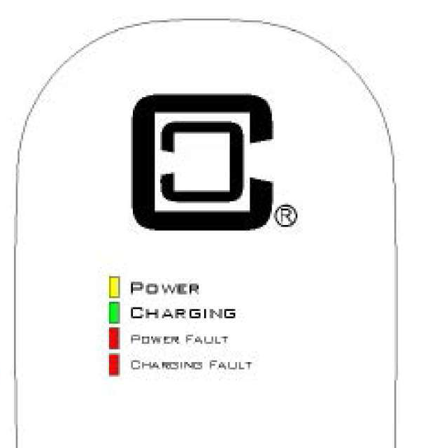
Figure 1
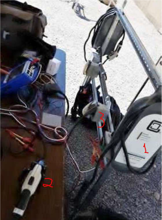
Installation at the USA Test Setup
• Weather conditions, 105 to 120 degrees F.
• HCS Maximum Operating Temperature: -30°C to +50°C (-22°F to +122°F)
• Two cars were used for testing
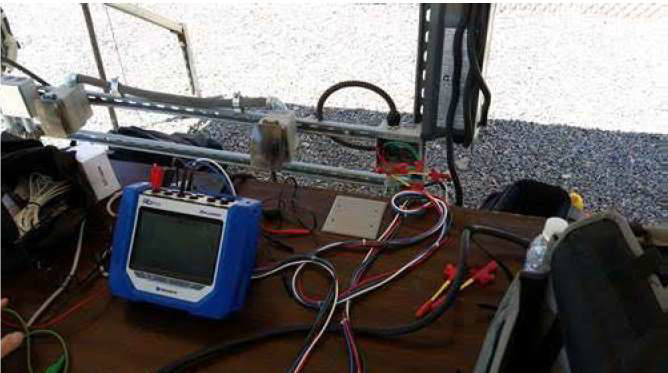
• Dranetz HDPQ Explorer with 3 range Flexi CTs for recording voltage and current
• Channel A was connected to the 208V input to NCS-40 charger control panel.
• Channel C was connected to a test cable from the charger to the car.
• Installed 1 each Dranetz PowerVisa PQ monitor at Charging post B.
Dranetz HDPQ monitor connected to incoming voltage of charger post.
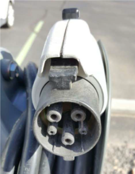
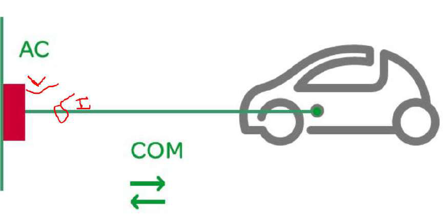
Connection from Charger pedestal to EV.
Tests and monitoring included
• Input and output voltage and current of NCS not attached to car.
• Input and output voltage and current of NCS when attached to car and while charging
• Input and output voltage and current when connecting and disconnecting from car.
• Input and output voltage and current when connecting a second charger to a second car.
• Several repeats of these items
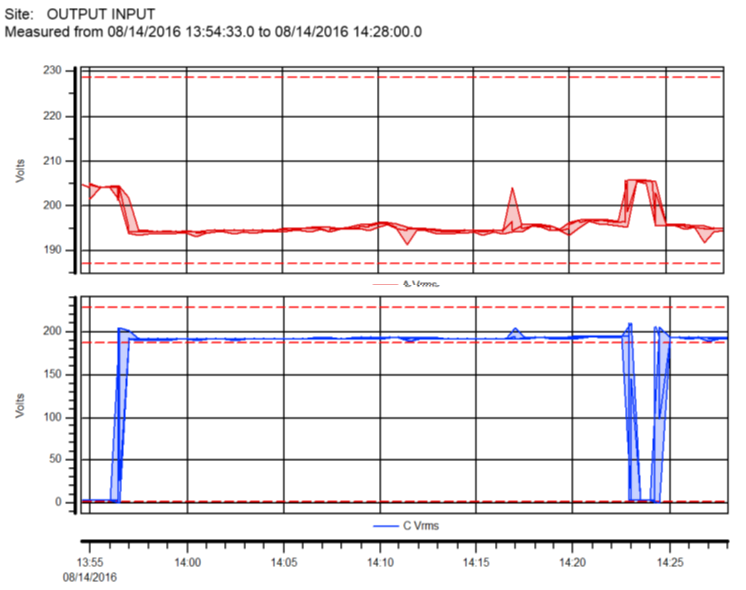
Figure 2: Input and output voltage of NCS when attached to car and while charging.
Test results
Input/output with an EV car not connected.
208-volt source voltage waveform from facility source was stable and within normal tolerance of +/-5%; frequency 60.0 hertz
No current and no 208-volt output. Small square wave output for signaling to EV car
Input/output with car connected.
• Output voltage delayed until car charger signal
• Output current delayed and slowly ramps up. More details needed. But apparent “soft start”
• Amazingly fast voltage transient recorded during connection time
• Voltage dropped when charging started.
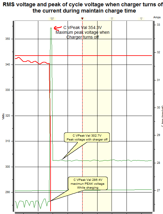
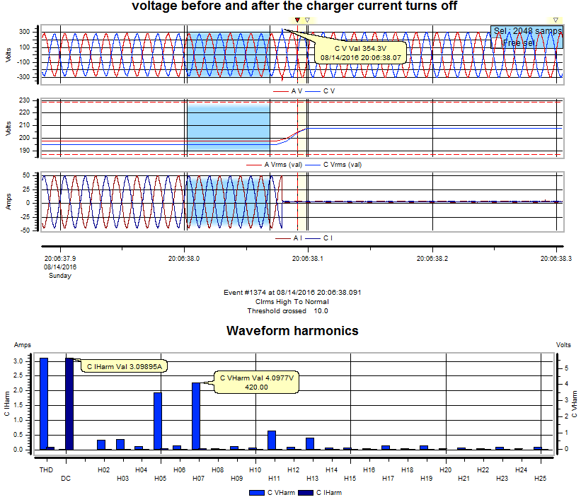
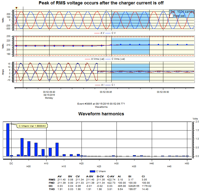
Input/output during charging switching off
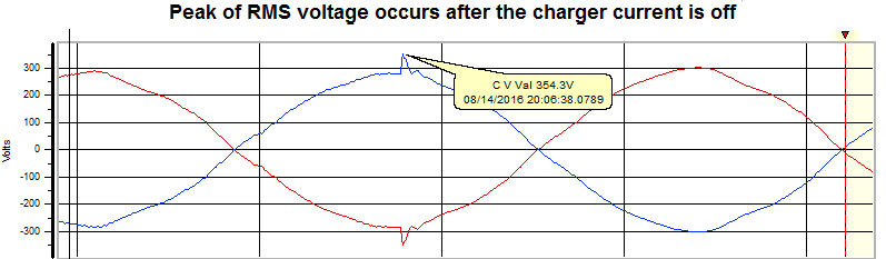
•When charger shuts off, voltage transient.
Harmonic voltage and current with charger on and off
Input/output during connection of second car
• Voltage dropped further when second car connected.
• No noticeable transient when second car connected.
• Harmonic voltage distortion increase…..
Change instrument setup to provide better details for inrush current.
• During connection to car and intermittent connection was observed. This may be a contributing factor. Further investigation required
Monitoring Vrms during charger testing long term graph show voltage surge during the charger connection test. No voltage sags occurred. (Figure 3)
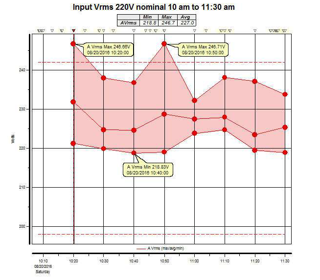
Figure 3
Voltage rise during test not due to testing of charger post or charger (Figure 4).

Figure 4
Source voltage variations with charger off (Figure 5).
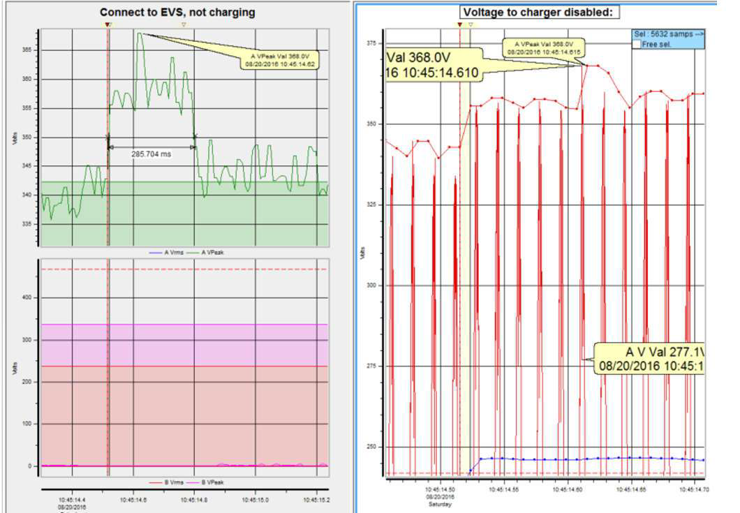
Figure 5
Source voltage transient to charger post (Figure 6).
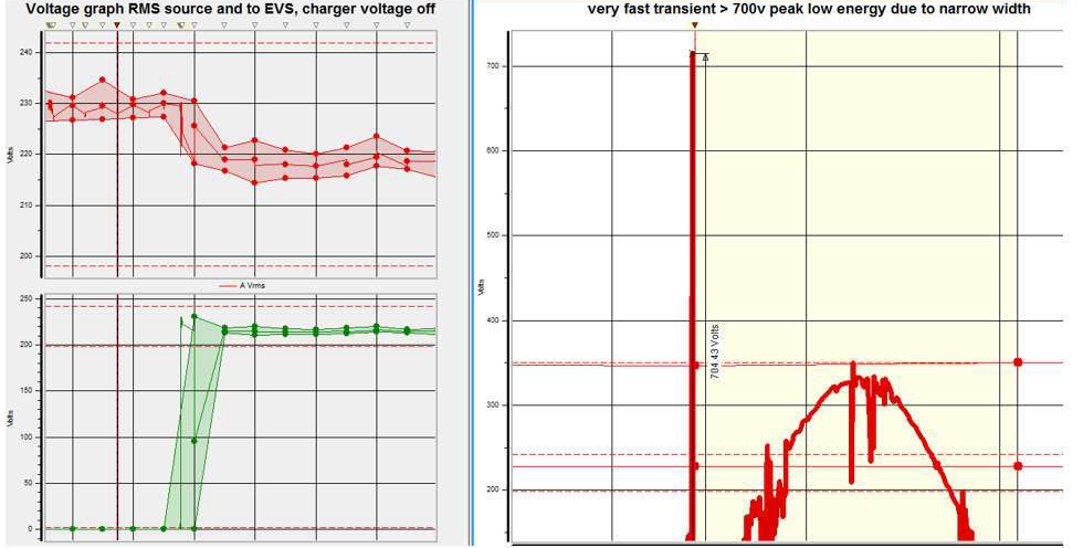
Figure 6
RMS Voltage variations due to charger operation (Figure 7).
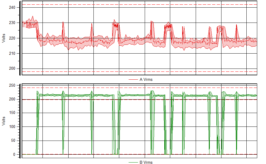
Figure 7
Harmonics charger on (Figure 8).
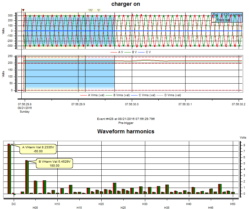
Figure 8
Harmonics charger off (Figure 9).
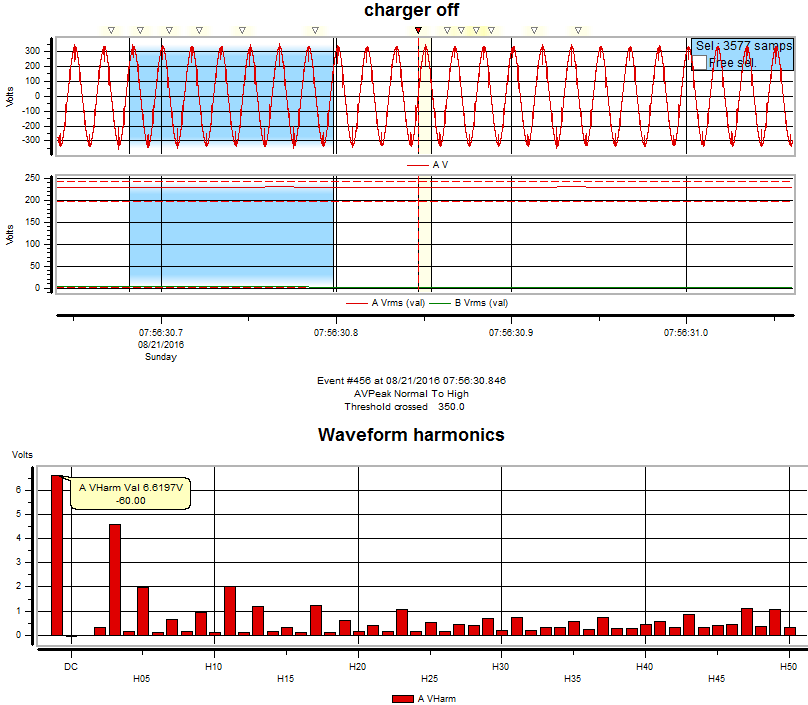
Figure 9
Summary
• Source voltage is fed direct to EV charger without filtering, regulation or surge protection.
• Harmonics increase when EV charger comes on is dependent on the source impedance and will vary site to site.
• The EV chargers are at risk to damage due to source voltage PQ events.
• Not all source voltage PQ issues are from the utility
• Some charger sites have transient voltage surge suppression.
• The EV charger loads will vary by EV manufacturer. Tested units showed charger current and supply voltage from the charger post are controlled by the EV charger.
