Published by Stanilav S. Girshin1, Aleksandr AY. Bigun1, Nikolay А. Mel’nikov1, Elena V. Petrova1, Vladislav M. Trotsenko1, Dmitry S. Osipov2, Vladimir N. Goryunov1, Omsk State Technical University (1), Yugra State University (2) Russian Federation
Abstract. One of the key indicators of the energy efficiency of electrical power systems should include the level of electric power losses. In a market economy, the significance of losses increases, since the cost of losses is an essential component of the tariff. One of the effective measures to reduce power network losses is reactive power compensation. However, the cost of compensating devices used for this purpose disagree with the task of reducing electric energy losses. The paper describes the effect of changing the capacity of static capacitor banks on the value of losses in the network with variation in the number of sections and the type of annual reactive load curves. The effect of the number of capacitor bank sections on the maximum reduction of annual reactive power losses in the network is analyzed. For the linearized load graphs, the relations for the values of natural losses in the capacitor banks are obtained, as well as expressions applicable to estimate the reduction of losses in the network. The conclusion is drawn that full reactive power compensation is impractical in most cases. The dependence of loss reduction on the power of capacitor banks reaches the maximum at the point where the battery power is less than the load power. It is proved that significant reduction of the loss in reactive power transmission in the electrical network requires no more than 3-4 sections (the reduction is close to 100 percent), and a 90 percent reduction in a wide range of load curves can be achieved with two sections.
Streszczenie. Do najważniejszych wskaźników efektywności energetycznej systemów elektroenergetycznych należy zaliczyć poziom strat energii elektrycznej. W warunkach gospodarki rynkowej wzrasta znaczenie strat, ponieważ koszt strat jest istotnym składnikiem taryfy na energię elektryczną. Jednym ze skutecznych działań mających na celu zmniejszenie strat w sieciach elektrycznych jest kompensacja mocy biernej. Jednak koszt wykorzystywanych do tego celu urządzeń kompensacyjnych stoi w pewnych sprzeczności z zadaniem zmniejszenia strat energii elektrycznej. W pracy przedstawiono wyniki wpływu zmiany mocy akumulatorów kondensatorów statycznych na wielkość strat w sieci przy zmienności liczby sekcji i rodzaju rocznych Wykresów obciążenia biernego. Przeprowadzono analizę wpływu liczby sekcji akumulatorów kondensatorów na maksymalne zmniejszenie rocznych strat w sieci na transmisję mocy biernej. Dla zlinearyzowanych Wykresów obciążenia uzyskuje się relacje opisujące wartości strat własnych w akumulatorach kondensatorów, a także wyrażenia mające zastosowanie do oceny redukcji strat w sieci. Stwierdzono, że pełna kompensacja mocy biernej jest w większości przypadków niepraktyczna. Wynik opiera się na tym, że maksymalna zależność redukcji strat od mocy akumulatorów kondensatorów jest osiągana w punkcie, w którym moc akumulatora jest mniejsza niż moc obciążenia. Uzasadnione jest twierdzenie, że nie więcej niż 3-4 sekcje są wymagane do znacznego zmniejszenia strat mocy biernej w sieci elektrycznej (zmniejszenie zbliża się do 100 procent), a zmniejszenie o 90 procent w szerokim zakresie Wykresów obciążenia można osiągnąć, gdy istnieją dwie sekcje. (Straty energii w sieciach elektrycznych z bateriami kondensatorów przy optymalnej kontroli mocy biernej)
Keywords: capacitor bank, energy losses, load graph, reactive power compensation, optimal control.
Słowa kluczowe: bateria kondensatora, straty energii, Harmonogram obciążenia, kompensacja mocy biernej, optymalne zarządzanie.
Introduction
Power factor compensation is one of the most effective measures to reduce energy losses in electrical networks [1– 5]. The majority of modern compensating devices allow for the control of reactive power. The controls provide the opportunity to reduce energy losses on the one hand, but they increase the cost of compensating devices on the other hand. Thus, the following tasks arise. The first one is a technical and economic comparison of compensating devices of the same power but with different control systems (in the particular case controlled and uncontrolled devices). The second task is an optimal power selection of compensating devices with allowance for control.
The works [2, 4] address methods for optimal selection of compensating devices taking into account the network topology, discreteness of nominal capacities and some other factors. Optimal reactive power control is essential for reliable and optimal operation of a power system. In the last few years, numerous strategies have been developed to solve the problem of optimal reactive power control. Since the problem is particularly important today, the number of articles in this area has not decreased. The paper [6] proposes a mathematical model for solving the optimization problem. This model depends on the network voltage. The target functions in the model are minimum capital costs for a static capacitor battery (SCB) with the possibility of switching by stages and minimum operating costs, depending on energy losses. The paper [7] describes a mathematical model based on the method of a set (swarm) of particles to determine the optimal location and power of the SCB. The model provides better voltage levels in the system, minimizes line losses and improves power factor. In the real-time tests in [8], a power factor correction system is proposed. The system is based on the use of multistage SCBs in combination with resonant filters. The developed approach allows finding the optimal parameters of the SCB to optimize the reactive power values. The results in [9] are related to implementing the current modern trend of simultaneous control of SCBs, generators and network distribution configuration. The advantage of the proposed method over existing algorithms to improve the efficiency of the power grid is indicated. The work [10] presents a significant list of articles on modern tools for solving reactive power optimization problems. An up-to-date analytical review is provided in [11]. The review is a universal source of information on methods for optimal reactive power distribution, minimizing losses, and increasing voltage stability. Though researchers have published numerous articles on the problem in question, the difference between regulated and unregulated SCBs in terms of energy losses requires thorough scientific scrutiny. This approach inevitably leads to installing capacitor banks with a minimum number of sections, as they are cost effective. In fact, this will only be true for even load curves. In all other cases, part of the time capacitor units will work with an incomplete number of sections leading to significantly different patterns of changes in energy losses. The paper considers the energy effects of regulated condenser units and analyzes the corresponding regularities.
Annual load changes and method of control
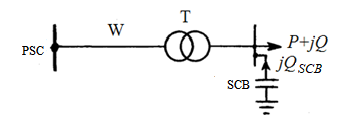
Let the SCB be controlled by the criterion of minimum energy loss. We consider overcompensation invalid, that is, between the reactive power of the load Q (t) and the operating power of the SCB QSCB at any time t, the ratio Q (t) ≥ QSCB must be fulfilled (Fig. 1). As shown in [12], the fulfillment of this condition is also a criterion for optimal control. If the reactive power of the load decreases with time, the next section of the SCB should be switched off only when the full compensation Q(t) = QSCB (cos φ = 1) is reached. Inherent losses of active power in the SCB are small, so the total losses in full compensation mode will be less than losses when one more section of the SCB is disconnected. Thus, any control of the SCB by the criterion of maintaining cos φ at a level less than unity is obviously not optimal.
Suppose that the annual reactive power curve can be approximated by a linear function of the following kind [13]:
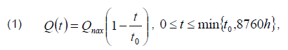
where Qmax is the annual maximum of reactive power; t0 is a graph parameter that characterizes the degree of its filling.
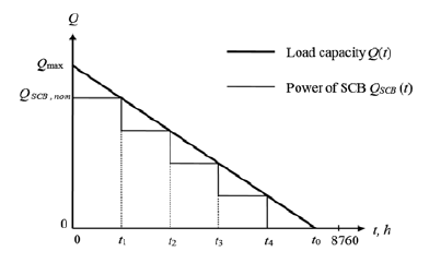
The work [6] show that this approximation gives good results when calculating energy losses. The process of SCB optimal control can be described graphically using the function (1) (Fig. 2).
Energy losses in SCB
We introduce the following notation:
QSCB, nom is the rated output of SCB;
n is the number of SCB sections;
Qс is a single section power;
psp is specific losses of active power in SCB (per unit of reactive power generated);
Qmin is the annual minimum of the reactive load power.
The number of unconnected sections (which are in operation all year round) can be determined by the expression
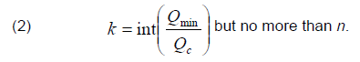
The value of Qmin in the accepted load curve model is determined by the formula (1) when substituting the upper limit of time t. If t0 ≤ 8760 h (which corresponds to the time of using the maximum reactive load Tmax,Q ≤ 4380 h), then the formula (1) gives Qmin = 0. This result may not correspond to real conditions. However, if the actual value of Qmin is not greater than the power of the SCB section, then we do not introduce the error, since the mode of complete shutdown of the SCB does not affect the loss components considered later.
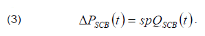
The active power losses of the SCB at every instant is proportional to the reactive power generated:
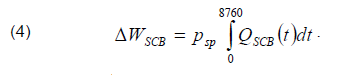
Annual energy losses in SCB are determined by the integral of the form
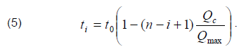
In fact, integration is reduced to summing the products of power losses at each stage of the annual BSC power curve by the duration of the stage (Fig. 2). The borders between ti stages represent the conditional moments of disconnection of the i-th SCB section. From Fig. 2 it directly follows that
Having performed integration, after some transformations it is possible to obtain the following formula for annual energy losses in SCB:
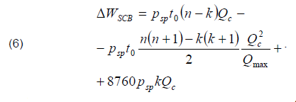
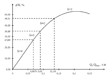
The first two summands together represent energy losses in the disconnected sections, and the last summand means losses in the sections operating without disconnection. Fig. 3 shows an example of the energy losses dependence in the SCB on the power of the section for a four-section SCB at t0 = 12000 h (in the area under the load curve this corresponds to Tmax,Q = 5560 h). Energy losses are expressed as a percentage of the losses that would occur under the year-round operation of the SCB with a Qmax capacity (i.e., with full compensation) equal to 8760 psp·Qmax.
The dependence is divided into four segments, which differ from each other in the number of sections k working without disconnection. Full compensation corresponds to the value Qc/Qmax = 0.25. Since it is less than the ratio of the minimum load power to the maximum (0.27 by the formula (1)), the segment where k = 0 is absent in this case.
Segments with different number of k are separated by break points. For k = 4, the dependence is linear. In subsequent segments, there are switching off sections, and the dependence becomes nonlinear resulted from the increase of the section power, when the duration of their operation decreases. At k = 1, the time factor becomes so significant that the dependence passes through the maximum and begins to decrease. The maximum losses in this case are 52.9%, and they are observed at Qc/Qmax = 0.207.
Energy losses in the network
Let us consider the influence of the regulated SCB on power losses in the network from the power supply center (PSC) to the low voltage (LV) buses of the transformer substation (Fig. 1). Formally, this effect applies to both load loss and no-load loss, and it is caused not only by changes in reactive power, but also by changes in voltage at the load node. However, the voltage in the load node depends not only on the capacity of the SCB, but also on the method of voltage regulation in the power center, as well as the modes of the power system as a whole. We assume that there is a counter voltage regulation in the power supply center, at which the voltage in some equivalent load node is maintained at a constant level. Let the LV buses of the substation under consideration correspond approximately to this node. This assumption permits excluding the influence of voltage on energy losses. As a result, we assume that the SCB affects only the load energy losses caused by the transfer of reactive power solely.
When choosing a SCB, it is not the absolute value of energy losses in the network that matters, but their reduction. Taking into account the accepted assumptions, the losses of active power in the line and transformer (Fig. 1) during the installation of the SCB at each moment reduce by the amount of
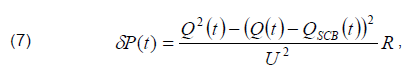
where R is the total active resistance of the line and transformer; U is the voltage at the load node (usually brought to the high side).
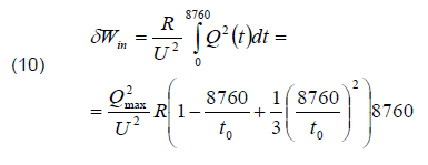
The annual reduction in energy losses in the line and transformer is equal to the integral of power losses reduction:
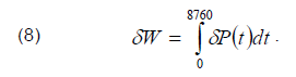
After integration and transformations, we finally obtain
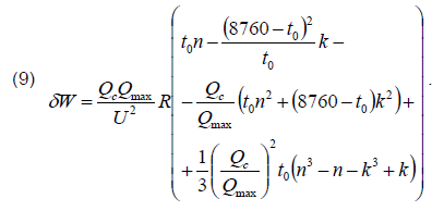
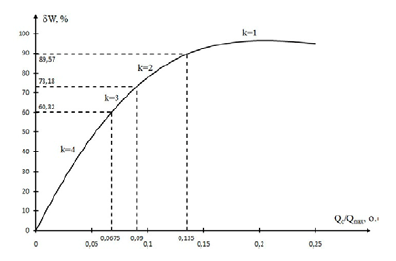
Fig. 4 shows the dependence of reducing energy losses in the network on the power of the SCB section, constructed under the same conditions as in Fig. 3. Reduction of energy losses is expressed as a percentage of losses for reactive power transmission before the SCB installation (in the initial mode), which are equal to
The resulting dependence passes through the maximum at Qc/Qmax = 0.207. The maximum loss reduction is 96.8%.
Effect of the number of sections on maximum loss reduction
We can write the reduction in energy losses in relative units explicitly by dividing (9) by (10):
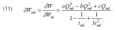
Let us introduce the following notation:
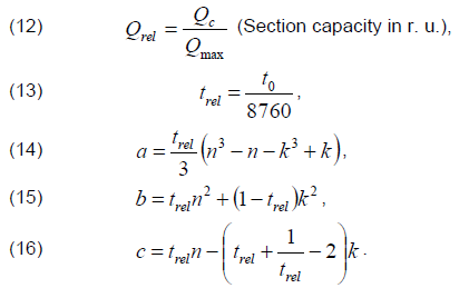
According to formula (11), the dependence of loss reduction on the power of the section in general is a cubic parabola that passes through the maximum at the point of
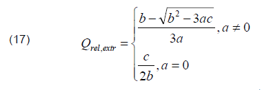
The formula (17) is true if the obtained value falls on the segment of curve δW(Qc), corresponding to the accepted value k. Otherwise, the maximum loss reduction will be located either at another segment of the curve or at the break point (at the segment border).
Table 1 shows the results of calculating maximum loss reduction δWrel,max at different times of using the maximum reactive load Tmax,Q and with different quantity of sections. The t0 values were determined on the equality of the areas under the load curves using the formula
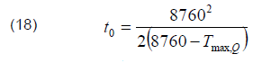
The calculation was performed in the range of Tmax,Q from 4380 to 0.875·8760=7665 hours. The value of 4380 hours corresponds to the maximum range of changes in the reactive load power. For smaller values of Tmax,Q, the same conditions will be observed as for 4380 hours, but with a reduced time scale. The limit value of Tmax,Q = 8760 hours was not considered, since the load curve becomes uniform, and the SCB will operate without regulation.
Table 1. Results of calculating the maximum loss reduction in the network
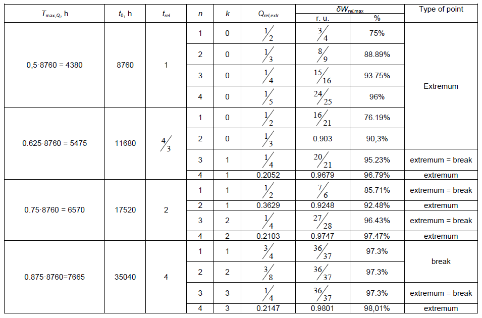
The maximum reduction in reactive power transmission losses varies from 75% for unregulated SCB and Tmax,Q = 4380 h to 98% for 4-section SCB and Tmax,Q = 7665 h. In the first case, the reactive load changes by 100% during the year, in the second case it changes by 25% of the maximum power. When Tmax,Q = 7665 h the maximum loss reduction practically does not depend on the number of sections, and for the number of sections n = 4, the maximum loss reduction practically does not depend on Tmax,Q, i.e. on the reactive load curve. The most significant effect is observed when switching from an unregulated SCB to a two section SCB.
Conclusions
1. Dependence of energy losses reduction in the network on the SCB capacity, taking into account the regulation, goes through the maximum, with the capacity of the SCB at the maximum point not reaching the highest load power. This means that full power factor compensation is impractical even in cases where the inherent losses in the SCB are small, and its cost can be ignored. This is equally true for unregulated SCB. The exception is a uniform load curve.
2. SCB with two sections allow reducing energy losses for reactive power transmission by 90% or more for almost any load curves. For 3 – and 4-section SCB, the loss reduction is close to 100%. Thus, to reduce energy losses, no more than three or four sections are required, and in most cases, one or two sections are sufficient. A larger number of sections is justified only in cases when it is necessary for voltage regulation.
REFERENCES
[1] Girshin S.S., Bigun A.AY., Petrova E.V., Goryunov V.N., Shepelev A.O., Ivanova E.V. The grid element temperature considering when selecting measures to reduce energy losses on the example of reactive power compensation, Przeglad Elektrotechniczny. 2018, vol. 94, No. 8. 101–104.
[2] Zhelezko Yu. S. Power factor compensation in complex electrical systems. – M.: Energoizdat, 1981, 200 p.
[3] RTM 36.18.32.6-92 “Instructions for the design of reactive power compensation units in the general-purpose power networks of industrial enterprises”..
[4] Ilyashov V.P. Capacitor installations of industrial enterprises. 3.- Moscow: Energoizdat, 1983, 152 с..
[5] Pasko M., Adrikowski T., Bula D., Blaszczok D. Power losses in the reactive power compensator built of capacitor banks and protective chokes, Przeglad Elektrotechniczny. 2020, vol. 96, No. 3. 166–169.
[6] Home-Ortiz J.M., Vargas R., Macedo L.H., Romero R. Joint reconfiguration of feeders and allocation of capacitor banks in radial distribution systems considering voltage-dependent models, International Journal of Electrical Power & Energy Systems. 2019, vol. 107, 298–310.
[7] Gonzalo G., Aguila A., Gonzalez D., Ortiz L. Optimum location and sizing of capacitor banks using VOLT VAR compensation in micro-grids, IEEE Latin America Transactions. 2020, vol. 18, 465–472.
[8] Abdelhady S., Osama A., Shaban A., Elbayoumi M. Real-Time Optimization of Reactive Power for An Intelligent System Using Genetic Algorithm, IEEE Access. 2020, vol. 8, 11991–12000.
[9] Fetouh T., Elsayed A.M. Optimal Control and Operation of Fully Automated Distribution Networks Using Improved Tunicate Swarm Intelligent Algorithm, IEEE Access. 2020, vol. 8, 129689–129708.
[10] Muhammad Y., Khan R., Raja M.A.Z., Ullah F., Chaudhary N.I., He Yi. Muha Solution of optimal reactive power dispatch with FACTS devices: A survey, Energy Reports. 2020, vol. 6, 2211–2229.
[11] Saddique M.Sh., Bhatti A. R., Haroon Sh.S., Sattar M.K., Amin S., Sajjad I.A., ul Haq S.S., Awan A.B., Rasheedd N. Solution to optimal reactive power dispatch in transmission system using meta-heuristic techniques―Status and technological review , Electric Power Systems Research. 2020, vol. 178, 106031.
[12] Girshin S. S., Goryunov V. N., Shepelev A. O. Optimal control of capacitor banks in distribution networks / Scientists of Omsk to the region. Materials of the II Regional scientific and technical conference. Under general ed. L. O. Stripling, Omsk, 2017, 75-79.
[13] S. S. Girshin, V. N. Goryunov, A. S. Shiryaev, D. V. Kovalenko. Selection of capacitor banks in electric networks taking into account disconnection at low loads / Industrial power engineering. 2019,no. 12, 12-18.
Authors: Stanilav S. Girshin, Omsk State Technical University, Mira, h. 11, 644050 Omsk, Russian Federation, e-mail: stansg@mail.ru; Aleksandr AY. Bigun, Omsk State Technical University, Mira, h. 11, 644050 Omsk, Russian Federation, e-mail: barsbigun@list.ru; Nikolay А. Mel’nikov, Omsk State Technical University, Mira, h. 11, 644050 Omsk, Russian Federation, e-mail: nik_mel_98@mail.ru; Elena V. Petrova, Omsk State Technical University, Mira, h. 11, 644050 Omsk, Russian Federation, e-mail: evpetrova2000@yandex.ru; Vladislav M. Trotsenko, Omsk State Technical University, Mira, h. 11, 644050 Omsk, Russian Federation, e-mail: troch_93@mail.ru; Dmitry S. Osipov, Yugra State University, Chekhov h. 16, Khanty-Mansiysk, Russian Federation, e-mail: ossipovdmitriy@list.ru; Vladimir N. Goryunov Omsk State Technical University, Mira, h. 11, 644050 Omsk, Russian Federation, e-mail: vladimirgoryunov2016@yandex.ru.
Source & Publisher Item Identifier: PRZEGLĄD ELEKTROTECHNICZNY, ISSN 0033-2097, R. 97 NR 9/2021. doi:10.15199/48.2021.09.23
