Published by Dawid ZIĘBA1, Jacek RĄBKOWSKI2, Medcom Company (1), Warsaw University of Technology, Institute of Control and Industrial Electronics (2) ORCID: 1. 0000-0003-3789-6851; 2. 0000-0001-8857-3505
Abstract. The article presents a discussion on the limitations of the flexible Rogowski current probes in the measurements of switching processes in ultra-fast SiC MOSFET power modules. The probes feature limited bandwidth of up to 50 MHz and might be susceptible to electromagnetic interferences caused by the rapid-switching processes. The obtained waveforms of the SiC MOSFET power module are compared to the waveforms captured using calibrated coaxial current shunt resistor that features a 2 GHz bandwidth.
Streszczenie. W artykule podjęto dyskusję nad ograniczeniami sond prądowych w formie elastycznych cewek Rogowskiego przy pomiarach szybkich procesów łączeniowych modułów tranzystorowych SiC MOSFET. Sondy te charakteryzują się ograniczonym pasmem przenoszenia do 50 MHz i mogą być podatne na zakłócenia elektromagnetyczne jakie towarzyszą szybkim procesom łączeniowym. Wykonano testy dwupulsowe i przebiegi uzyskane przy pomocy wybranych trzech cewek Rogowskiego porównano z przebiegami zarejestrowanymi przy użyciu skalibrowanego koaksjalnego bocznika rezystancyjnego o paśmie przenoszenia 2 GHz. (Elastyczne cewki Rogowskiego w pomiarach szybko przełączających modułów tranzystorowych SiC MOSFET – ograniczenia i wyzwania ).
Keywords: SiC MOSFET, fast-switching, power modules, Rogowski coils.
Słowa kluczowe: SiC MOSFET, szybko przełączające, moduły tranzystorowe, cewki Rogowskiego
Introduction
Recently, the status of Silicon Carbide (SiC) semiconductors in the power electronic industry came to the point where these devices have become a standard choice for innovative, high-efficiency solutions. In the automotive sector, responsible for the majority of the SiC market growth, main players already use SiC components in their long-range electric vehicles (EVs) [1-5]. Apart from the automotive sector, rolling-stock companies also apply SiC semiconductors as a standard solution for high-efficiency converters dedicated to trains, trams, and other public transport vehicles [6-9]. According to market research, the global market for SiC power devices is expected to grow by 41,4% year-on-year in 2023 [10]. That is caused mainly by the chip-makers joining collaborative relationships with the transportation and renewable energy sectors. These trends are expected to remain the same for at least the next five years. Even though SiC-based devices are most often more expensive compared to classic silicon (Si) based solutions, the gains from higher efficiency, smaller and lighter power electronics converters, and potentially more extended range on the same battery in the case of EVs bring SiC components to the top choice position and definitely will affect the semiconductors market share in the following years. However, as the switching speed of new transistors increase, new challenges appear. One of the main issues important in the design process of power converters is proper measurements of the transistor voltages and currents to find switching energies. Especially current measurement technologies are the main problem due to bandwidth limitations. In the case of power modules discussed in this paper, the most common current probes are Rogowski coils, current transformers, and current shunts. Among these three, the flexible Rogowski coils are the ones that are the most versatile. However, speaking of flexible Rogowski coils, they feature relatively low bandwidth, recently of up to 50 MHz [11]. Taking into consideration that SiC MOSFETs can switch hundreds of amps in tens of nanoseconds, the question arises whether these current probes are suitable for new power modules. In a Tektronix application note [12], one can read that Rogowski coil current probes are unsuitable for SiC MOSFET power modules current measurements.
However, only a coil with a bandwidth limited to 30 MHz has been tested. On the other hand, a manufacturer of a 50 MHz Rogowski coil current probe selected in this paper clearly states that it has been optimized for fast-switching devices such as SiC [11].
In this article, a comparison of the performance of selected flexible Rogowski coil current probes available on the market, featuring bandwidth in the range of 23-50 MHz with the reference of a 2 GHz bandwidth coaxial current shunt resistor, is presented. A rapid-switching SiC MOSFET module (Microchip MSCSM120AM042CT6LIAG) has been selected for measurements according to a standard double pulse test (DPT) technique [13]. The experimental results are presented and discussed.
New challenges related to fast switching capabilities of SiC semiconductors – transistor current measurements
As mentioned above, SiC MOSFET power modules have become common building blocks for high-power new generation power electronics converters. As their switching behavior is far different compared to the one well known from their silicon counterparts, Si IGBTs, which exhibit much slower switching, additional phenomena related to the parasitic parameters of the semiconductors and the whole power loops must be considered [14]. Otherwise, the obtained results of performed measurements might be highly erroneous [15]. As an effect, the designed power electronics converters might be far from optimal. Apart from that, in order to be able to perform the measurements of new-generation rapid-switching SiC MOSFET modules correctly, special care has to be taken considering not only the power loop but also the measuring rig itself.
Nowadays, SiC MOSFET transistors in power modules are capable of switching with drain-source voltage slopes exceeding 50 kV/μs while switching nominal currents of hundreds of amps in tens of nanoseconds. Moreover, the next generations of SiC semiconductors are expected to gain even faster switching capabilities. That fast switching processes are accompanied by significant radiation of electromagnetic interferences (EMI) that might affect the output signals of the measuring voltage and current probes.
For drain-source voltage measurements, differential, high-bandwidth, and high common mode rejection ratio (CMRR) voltage probes are strongly advised to be used in order to minimize the distortions of the waveforms. Considering the current measurements, the transistor current can be measured either using a Rogowski coil, a current transformer, or a coaxial current shunt resistor (CCSR) [16]. The best option seems to be CCSRs, as they feature a bandwidth as high as 2 GHz [17]. However, they are challenging to apply in real industrial applications, as in most cases, they need mechanically sophisticated power loops that are often far from optimal considering the busbar design connecting the power module with the DC-link capacitors, with minimized parasitic inductance. The same observations are valid in the case of current transformers (CTs). Present-day current transformers achieve measurement bandwidths of up to 250 MHz [18]. Nevertheless, this comes with a trade-off, as the magnetic core saturation limitation necessitates a relatively large cross-sectional area, resulting in relatively huge dimensions. It is important to notice that the usage of both CCSR or CTs, in most cases, substantially increases the overall parasitic inductance of the power loop. In the case of a CCSR, that is caused by the current leads that are not fully magnetically coupled, even if minimized in length. Considering the CT case, the increase of parasitic inductance in the power loop might be so high due to the parts of busbars that are not magnetically coupled that it might eliminate the reasonableness of their use. Moreover, changes in the parasitic inductance of the power loop influence the amount of energy stored in the distributed parasitic inductance over the whole power loop and its resonance frequency, which directly impacts the switching waveforms.
An alternative solution is a widely-used current sensor: the Rogowski coil (RC), which relies on Faraday’s induction law [19,20]. Employing a helix coil, it directly captures the derivative of the current, subsequently reconstructing the original current signal through either a passive or active integrating circuit (figure 1), as described by equation 1.
where: vROG – the voltage at the Rogwoski coil terminals, μ0 – vacuum permeability N – number of turns, A – the winding area, r – radius between the center of the conductor and the winding, M – the mutual inductance of the Rogowski coil.
That type of current probe is a common way of measuring a power module transistor current during double-pulse tests. However, regarding flexible Rogowski coil current probes (RCCP) that are very practical in fast prototyping and can easily be used in tests of power modules in various packages, unfortunately, they exhibit considerable limitations. Recently, they feature a limited bandwidth of up to 50 MHz but more common flexible RCCPs on the market feature even lower bandwidth in the 20-30 MHz range.
A comparison of the performance of RCCPs to the 2 GHz bandwidth calibrated CCSR
Three commonly available on the market Rogowski coil current probes have been selected for test purposes. CWTMini50HF/15, CWTUM30, and CWTMiniHF30 models (all manufactured by PEM company) with bandwidths of 50 MHz, 30 MHz, and 23 MHz, respectively, have been tested. A calibrated CCSR Powertek SDN-414-10 with 2 GHz bandwidth has been used as a reference current sensor. To fully use the rapid-switching capabilities of new generation SiC MOSFET power modules, a sophisticated double-pulse test-bench based on the Advanced Conversion 700D590 power ring film capacitor and dedicated busbars has been prepared.
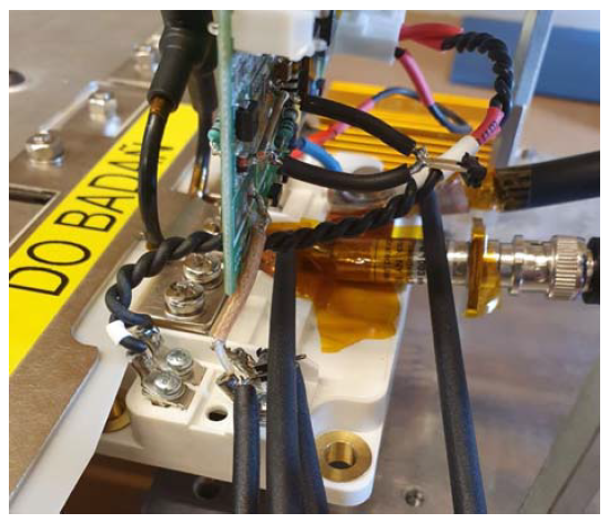
The Microsemi MSCSM120AM042CT6-LIAG 1200 V, 495 A SiC MOSFET module was connected to laminated busbars designed to allow a CCSR insertion into the power loop. The CCSR underwent mechanical modifications in order to minimize the additional parasitic inductance added into the power loop. As a result, a total parasitic inductance was limited to 24 nH even with the CCSR installed. The SiC MOSFET power module under test with the CCSR and 50 MHz bandwidth Rogowski coil installed in the power loop has been presented in figure 2.

In addition, the custom-made air core 50 μH inductor has been used as a load inductance. The MOSFET gate has been driven by a modified high-performance low output impedance gate driver from the Medcom company, providing voltages of +20 V/-5 V, as recommended by the manufacturer of the tested SiC power module. In order to achieve the fastest switching possible, no additional external gate resistor was included in the gate loop (RG = 0 Ω). The gate driver output and the MOSFET under test gate and source connection terminals were connected using a short high-bandwidth coaxial cable to minimize parasitic inductance in the gate loop. The drain-source voltage waveforms of the SiC MOSFET transistor under test were obtained using Tektronix THDP0200 differential voltage probe. A Tektronix MSO46 series oscilloscope has been used to capture the waveforms. Output signals of voltage and current probes were precisely time-aligned using a method described in [14]. Considering the intentionally imperfect (non-central) placement of the Rogowski coil relative to the primary conductor in this research work, an accuracy of ± 2% is expected, according to the manufacturer. An operating point with a power supply voltage of 600 V has been chosen, as the DUT is a 1,2 kV class device. The DPT tests have been performed with all three selected Rogowski coils one after another, as it was impossible to fit all three at the same time on optimized low parasitic inductance busbars.
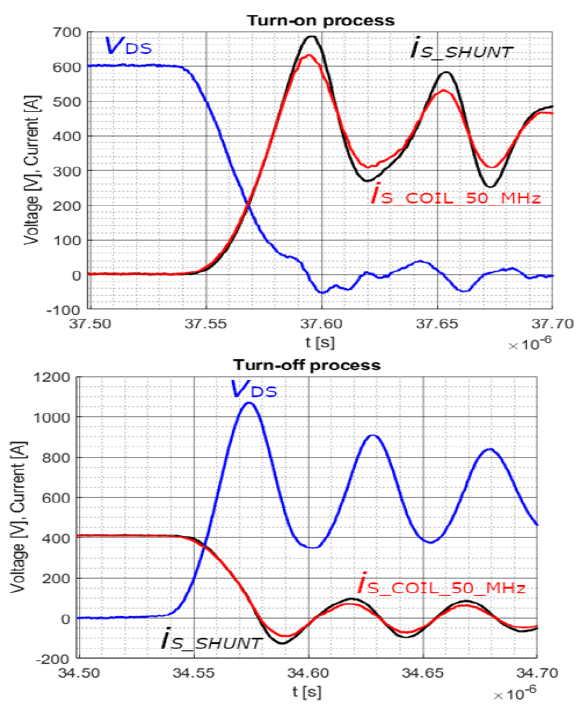
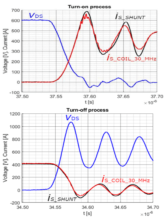
Selected turn-on and turn-off waveforms recorded during the switching of 400 A source current are presented in figures 3-5. They show a comparison of current waveforms obtained with RCCPs and reference CCSR. It shows that after the time alignment, the main slopes for both turn-on and turn-off processes are quite similar in shape compared to the reference waveform of the coaxial shunt resistor. However, the shapes of the current waveforms obtained by the RCCP are distorted, especially in the post-switching oscillation phase. The lower the bandwidth of the RCCP is, the more the particular waveform is distorted. The RCCP featuring 50 MHz bandwidth provided the waveform with significantly reduced amplitude of the oscillations (76% of the amplitude in the CCSR waveform), even though the oscillations frequency is 17,15 MHz, which is far from the claimed 50 MHz bandwidth (-3 dB). The shape, on the other hand, is reproduced reliably without significant distortions caused by EMI. The 30 MHz bandwidth RCCP performed similarly to the 50 MHz RCCP, but significantly greater distortions in the waveform can be observed. That means that 30 MHz RCCP is more susceptible to EMI. The measured current waveforms might be far from reality, suggesting huge oscillations in the power module itself, unequal current sharing between the chips inside the module, or poor gate-source voltage control in the power module under test. In the case of 23 MHz RCCP (Fig. 5), the current shape is significantly distorted and out of phase. That shows substantial susceptibility to EMI radiated during rapid switching processes. This RCCP is definitely not suitable for measurements of fast-switching SiC MOSFET power modules, as obtained waveforms are not reliable. In the authors’ opinion, this is caused mainly due to the susceptibility of the selected RCCP to the EMI occurring during fast switching processes.
All in all, unfortunately, all the selected RCCPs did not fully meet the criteria of reliable, current waveform reproduction, suggesting that further research and development of higher bandwidth flexible RCCPs that are immune to the EMI is needed.

Conclusions
The results of performed measurements show that commonly used in the industry, flexible RCCPs with bandwidths of up to 50 MHz might not be fully suitable for rapid switching SiC MOSFET power modules. In addition to mismatches during the current rising or falling phase, the obtained current waveforms suggest not-existing high-frequency oscillations. Moreover, the waveforms might be distorted due to the susceptibility of RCCPs to the electromagnetic interferences that occur during fast switching processes. On the other hand, using CCSRs in power loops significantly changes the parasitic parameters of the power loops, directly influencing the switching behaviors. That shows the necessity for further research and development of flexible RCCPs featuring higher bandwidth with better immunity to electromagnetic interferences. At the moment, RCCPs seem to be the most suitable solution, but the possible errors and mismatches must be kept in mind when the performance of SiC power modules is evaluated.
REFERENCES
[1] Robles E., Matallana A., Aretxabaleta I., Andreu J., Fernandez M., Martin J., The role of power device technology in the electric vehicle powertrain, International Journal of Energy Research, vol. 46, Issue 15, 22222-22265
[2] Yadlapalli R., Tagore K., Anuradha K., Rajani K., Chandra S., A review on energy efficient technologies for electric vehicle applications, Journal of Energy Storage, vol. 50, Issue January, 104212
[3] Comyn R., SiC Power Device Competitive Landscape: A Patent Perspective, PCIM Europe 2023, 09 – 11 May 2023, Nuremberg
[4] Kumar A., Moradpour M., Losito M., Franke W., Ramasamy S., Baccoli R., Gatto G., Wide Band Gap Devices and Their Application in Power Electronics, Energies 2022, vol. 15, 9172
[5] Rąbkowski J., Harasimczuk M., Kopacz R., Sobieski R., Three-Level Interleaved Non-isolated DC/DC Converter as a Battery Interface in an EV Charging System with Bipolar DCLink, Przegląd Elektrotechniczny, 2023, Issue 5, 202
[6] Helsper M., Ocklenburg M., SiC MOSFET Based Auxiliary Power Supply for Rail Vehicles, 20th European Conference on Power Electronics and Applications (EPE’18 ECCE Europe), 2018, 1-8
[7] Shepard P., 175 kVA SiC Converters in the New Dragon 2 Locomotive, 2018, Online. Available: https://eepower.com/news/175kva-sic-converters-in-the-newdragon-2-locomotive/ (Accessed 2022-07-21)
[8] Lindahl M., Velander E., Johansson M. H., Blomberg A., Nee H., Silicon Carbide MOSFET Traction Inverter Operated in the Stockholm Metro System Demonstrating Customer Values, 2018 IEEE Vehicle Power and Propulsion Conference (VPPC), 2018, 1-6
[9] Biliński J., The latest generation drive for electric buses powered by SiC technology for high energy efficiency, MATEC Web of Conferences, vol. 180 (2018)
[10] Telford M., SiC power device market rising 41.4% to $2.28bn in 2023, Semicontuctor Today, compounds & advanced silicon, vol. 18, 2023, March, Issue 2, 6-6
[11] Power Electronics Measurements, Online. Available: https://www.pemuk.com/products/cwt-currentprobe/cwtmini50hf.aspx (Accessed 2023-07-29).
[12] Effective Measurement of Signals in Silicon Carbide (SiC) Power Electronics Systems, application note, Online. Available: https://download.tek.com/document/Effective-Measurement- SiC-Power-Systems_48W-73812-0.pdf (Accessed 2023-09-30).
[13] Microchip Microsemi MSCSM120AM042CT6LIAG SiC MOSFET power module datasheet, Online. Available: https://www.microchip.com/en-us/product/MSCSM120AM042CT6LIAG-Module (Accessed 2023-07-29).
[14] Zięba D., Rąbkowski J., Problems related to the correct determination of switching power losses in high-speed SiC MOSFET power modules, Bulletin of the Polish Academy of Sciences: Technical Sciences, vol.70, 2022, Issue 2
[15] Zięba D., Rąbkowski J., Dynamic performance evaluation of ultra-fast SiC MOSFET power module – a comprehensive approach, Przegląd Elektrotechniczny, 2023, Issue 5, 190
[16] Zhang Z., Guo B., Wang F., Jones E., Tolbert L., Methodology for Wide Band-Gap Device Dynamic Characterization, IEEE Transactions on Power Electronics, vol. 32, Issue 12, 9307–9318
[17] T&M Research, Current Viewing Resistors, Online. Available: https://www.tandmresearch.com/index.php?page=products (Accessed 2023-07-29)
[18] Pearson Electronics, Pearson Current Monitor, Online. Available: https://www.pearsonelectronics.com/pdf/7713-03.pdf (Accessed 2023-07-29).
[19] Rogowski W., Steinhaus W., Die Messung der magnetischen Spannung, Archiv fur Elektrotechnik, vol. 1, 1912, Issue 4, 141-150
[20] Samimi M., Mahari A., Farahnakian M., Mohseni H., The rogowski coil principles and applications: A review, IEEE Sensors Journal, vol. 15, 2015, Issue 2, 651-658[19] Ma H., Yang Y., Wu L., Wen Y., Li Q., Review of the designs in low inductance SiC half-bridge packaging, IET Power Electronics, vol. 15, 2022, Issue 11, 989-1003
Authors: Dawid Zięba, Medcom Company, Jutrzenki 78A, 02-230 Warsaw, E-mail: dawid.zieba@medcom.com.pl; Jacek Rąbkowski, Warsaw University of Technology, Institute of Control and Industrial Electronics, Koszykowa 75, 00-662 Warsaw, E-mail: jacek.rabkowski@pw.edu.pl.
Source & Publisher Item Identifier: PRZEGLĄD ELEKTROTECHNICZNY, ISSN 0033-2097, R. 100 NR 7/2024. doi:10.15199/48.2024.07.01
