Published by Paweł PTAK1, Tomasz PRAUZNER2, Henryk NOGA3, Piotr MIGO3, Agnieszka Gajewska3, Politechnika Częstochowska, Katedra Automatyki, Elektrotechniki i Optoelektroniki (1), Uniwersytet Jana Długosza w Częstochowie, Katedra Pedagogiki (2), Uniwersytet Pedagogiczny w Krakowie, Instytut Nauk Technicznych (3)
Abstract. The paper presents a study on an electromagnetic inductive sensor for detecting and locating faults in protective coatings. The accuracy of the sensor was tested by means of periodic signals of various frequency. A number of measurements were performed for selected signals in order to select required frequencies and to determine the sensitivity and accuracy of the inductive sensor. The possibility of minimising measuring errors was also addressed. Once the frequency and shape of the signal is selected, a multi-frequency binary signal is generated for testing multi-layer anticorrosion coatings. Performing a measurement with a number of different frequencies at a time makes it possible to eliminate sources of errors, such as the necessity to repeat measurements at the same place. The measuring system employs the programming package DasyLab by National Instruments.
Streszczenie. Artykuł prezentuje wyniki badań czujnika elektromagnetycznego indukcyjnego, który będzie w stanie wykryć i zlokalizować wady w badanych powłokach ochronnych. Przedmiotem badań będzie ocena możliwości zastosowania opracowanego inteligentnego systemu pomiarowego na potrzeby przemysłu energetycznego. Sprawdzono dokładność czujnika przy zastosowaniu sygnałów okresowych o różnych kształtach. Dla wybranych rodzajów sygnałów przeprowadzono szereg pomiarów dobierając częstotliwość, określając czułość i dokładność czujnika indukcyjnego oraz oszacowano możliwości zmniejszenia błędów pomiarowych. Dobór częstotliwości i kształtu ma posłużyć zastosowaniu wieloczęstotliwościowych sygnałów binarnych do badania wielowarstwowych powłok antykorozyjnych. Pozwoli to na pomiar wieloma częstotliwościami jednocześnie aby uniknąć szeregu źródeł błędów takich jak powtarzalność miejsca pomiaru. Przedstawiony system pomiarowy wykonano przy zastosowaniu pakietu programowego DasyLab firmy National Instruments. (System pomiarowy do badania stanu powłok ochronnych urządzeń elektroenergetycznych)
Keywords: intelligent measuring system, inductive sensor, modeling, frequency selection, coatings, field measurements of power devices
Słowa kluczowe: inteligentny system pomiarowy, czujnik indukcyjny, badania modelowe, dobór częstotliwości i rodzaju sygnału, powłoki ochronne, pomiary poligonowe konstrukcji energetycznych
Introduction
A coating is a layer of material created in a natural way or applied on the surface of an object made of a different material in order to obtain desired technological or decorative properties. The coatings applied for both purposes should also meet requirements concerning their appearance, quality, thickness, strength and durability [1,2].
There exists a wide array of devices used for testing the coating parameters, the number of which can be extensive, with individual parameters being tested in a number of ways depending on the standard selected for reference.
Measurements of the thickness of outer layers or coatings are performed in numerous branches of industry, such as automotive, food, electrotechnological, electronic, aviation, metallurgical, computer, telecommunications and plastics industry [3,4,5]. Various types of coatings have to conform to specific standards [6,7,8,9,10].
One of the most widely applied in industry metal coatings is the zinc one. Its durability depends on its thickness and the exploitation conditions. The requirements concerning testing the parameters depend on the production method and also on the function of the element on which the coating has been applied.
Despite the constantly improving quality of anticorrosion coatings, it is corrosion that causes the majority of faults or deterioration of exploitation parameters in devices. Metal elements can be protected from corrosion in a number of ways, one of which is applying zinc, paint, bitumen, or other protective coatings.
Since protective coatings are intended to provide both mechanical strength and electrochemical resistance to corrosion, they consist of a number of layers. Typically, the surface of an element is first covered by a zinc layer and then by a paint layer. Since paint cracks easily, detrimental factors causing corrosion get inside and destroy the layer which is invisible from the outside. Because of that, corrosion is difficult to detect and poses a serious threat to construction elements of the power system. With the internal zinc layer being inaccessible to inspection by means of classical instruments for measuring outer layers, it is necessary to develop alternative nondesctructive methods suitable for this kind of measurement performed during exploitation [1,2,3,4].
Inductive measuring sensors
The subject of the present study is transformer sensors. The magnetic circuit of the sensor consists of the coating and substrate under scrutiny. The coating is a gap in the circuit. The inductivity of the sensor varies with the gap dimensions and the variation is nonlinear.
The sources of measuring errors in inductive sensors can be classified as:
1. Hardware sources, such as power supply instability, accuracy of the instrument collaborating with the sensor, imprecision of the sensor construction, size of the sensor active surface, supply frequency, size of the surface under examination;
2. Sources related to the object examined and ambient conditions, such as surface roughness, shape of the object, edge effect, temperature, influence of external fields, etc.
Hardware sources of errors can be minimised, but errors related to the object under examination can hardly be eliminated as they are part of the measurement itself. Technological standards stipulate the size of a surface to be tested. However, it is still possible to minimise the influence of such errors to some extent. For example, the influence of the change in the temperature measured in the resistance of the inductive sensor windings can be minimised by applying differential systems. The effect of the surface shape or roughness is minimised by downsizing sensors.
Preliminary examination of the inductive sensor
A preliminary selection of the kind of signal and its frequency provides a basis for designing a multi-frequency binary signal (MBS), by means of which it is possible to measure the thickness of a coating and to test the material against delamination (i.e. to test if a third layer has not appeared).
In the laboratory measurements samples of protected car body steel were used, consisting of a steel substrate coated with a layer of zinc and a layer of protective paint. Then, measurements were performed by means of a transformer sensor and compared to the results obtained by means of thickness gauges of known accuracy manufactured by Fisher [13]. Fig. 1 presents the results of the measurements, with accuracy at the level of 1%.
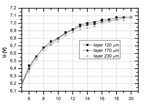
The greatest sensitivity of about 2 mV/µm for a sinusoid measuring signal was attested in the frequency range 11 kHz to 18 kHz. The sensitivity value was calculated on the basis of the measurement data and averaged for that range.
The thickness gauges were also used for measuring the joint thickness of zinc and paint. The accuracy of the measurements was assessed by means of statistical methods, after having performed a number of measurements on previously prepared samples of protective coatings. The accuracy analysis of the measurements performed by the author-designed system were subsequently compared to the data obtained by means of manufactured gauges. The juxtaposition of the results is presented in Fig. 2 [7,8,9,10].

To obtain the value of the standard deviation s, measurements were carried out on two coatings, coating 1 – 120 µm thick and coating 2 – 170 µm thick, with a signal of frequency 1 kHz. 30 measurements were taken for each thickness and for each sensor altogether.
After a series of experiments and analyses, the idea was put forward that the measurements should be performed in two steps:
1. Preliminary measurements intended to recognise the kind of protective coating, select a frequency and create the MBS consisting of 3÷5 frequencies in the range;
2. Measurements proper by means of the MBS.
Intelligent measuring system
There are various kinds of instruments for measuring the thickness of multilayer coatings available on the market. One of them is PHASCOPE® PMP10 DUPLEX [13], manufactured by Fischer, used for measuring the thickness of multilayer coatings both on magnetic and non-magnetic substrates [11]. The instrument is not however suitable for measuring the thickness of coatings made of zinc alloys, such as ZnNi or ZnFe, which restricts the range of its applicability.
The intelligent two-phase measuring system under design can be used for measuring the thickness of conductive coatings, such as zinc, together with protective layers on the power system construction or car body elements. The two-phase operation of the device includes recognising a protective coating, selecting a frequency range and forming a MBS consisting of a number of frequencies suitable for the measurement as the first step and the measurement proper by means of the MBS as the second step.
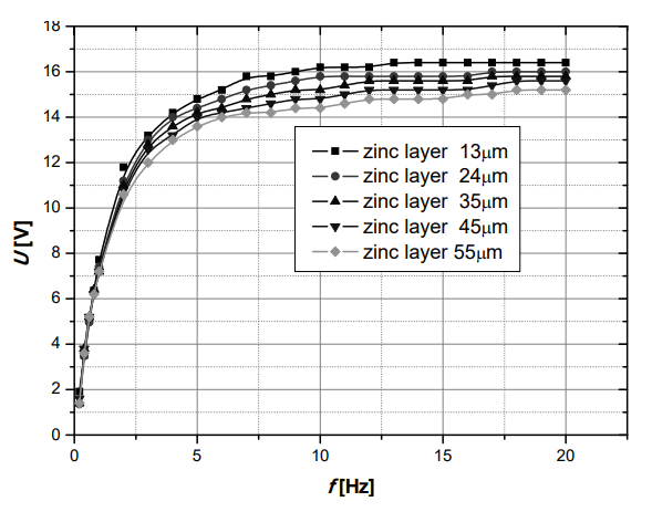
At the preliminary stage of the study, the total thickness of the protective coatings can be measured by means of the inductive method. The thickness of the conducting layer cannot be measured directly since it is located under the external protective non-conducting layer, such as paint. The zinc coating located under the paint layer can be measured by means of an inductive transformer sensor. To verify the usefulness of this method in the first stage of the study, test measurements on zinc coatings 13 µm, 24 µm, 35 µm, 45 µm and 55 µm thick on a 1mm thick ferromagnetic substrate were carried out. The external paint layer was selected in such a way that the joint thickness of both layers, i.e. the zinc one and the paint one was 70 µm. Because of that, the sensor does not respond to variation in the total thickness of the two-layer coating, which is constant, but to the variation in the zinc layer. Fig. 3 presents selected measurement results of the thickness of various zinc coatings.
In the measuring system under design, a transformer sensor will be applied, with a multi-frequency supply signal. When the measuring signal consists of a number of frequencies, it is possible to measure the thickness of conducting and non-conducting layers in a single measurement [6,8].
On the basis of the preliminary results obtained, the intelligent measuring system selected a few component frequencies of the MBS (6 kHz, 8 kHz, 10 kHz and12 kHz) for the case under discussion. For these frequencies, the sensitivity to the changes in the zinc coating thickness was the greatest. The frequencies were selected in such a way as to enable a measurement of a non-ferromagnetic layer, i.e. zinc, by means of two frequencies 6 kHz and 8 kHz. To measure the thickness of the zinc-paint coating on a magnetic substrate, the system selected the frequencies 10 kHz and 12 kHz. The measuring system was modelled by means of the software package DasyLab [12] in two variants, corresponding to two phases of the measurement. In the first variant, presented in Fig. 4, four measuring paths were simulated for a pre-selected frequency of the measuring sensor. Each measuring path corresponds to one frequency of the signal, the amplitude of which can be adjusted. The system computes the maximal value of the signal amplitude for a prescribed number of periods and then determines an average thickness of the zinc coating. On the basis of the results obtained, the component frequencies of the MBS are subsequently determined.

In the second variant, there is only one measuring path (Fig. 5) for the second phase of the measurement carried out by means of a MBS generated in the preliminary phase.

The four modelled signals were combined into one resultant measuring signal. On the basis of its value, the system computes the maximal amplitude, with the prescribed number of signal periods. After these quantities have been determined, the system returns the thickness of the zinc coating.
Applying a few selected frequencies of the sinusoid signal simplifies the measurement by eliminating the need for time-consuming analysis. Because of this, it is possible to apply the method under regular exploitation of the power network, without switching it off. This, in turn, significantly reduces the cost of testing.
Based on the DasyLab package, the measuring system offered in the study enables interactive setting of the measuring signal parameters in response to the varying conditions of the measurement. The standard measuring instruments available on the market, such as Fischer PMP10, are closed systems which do not offer a possibility of modifying their software or the parameters of testing signals.
In both variants of the measuring-diagnostic system it is possible to adjust the amplitude of each component of the MBS, it is also possible to set frequencies different from those obtained in preliminary measurements. The possibility of altering the amplitude is especially useful since with the unmodified value of amplitude, the system can transgress its linear range of operation, thereby increasing the measurement error.
Concluding remarks
1. The inductive sensor under study can be used for measuring the thickness of protecting coatings as long as it is small with respect to the thickness of a substrate. The measuring signal frequency ranges from 1 to 20 kHz. Due to the fact that the depth of the measuring signal penetration into the coating on a ferromagnetic substrate decreases as the frequency increases, it is necessary to select the signal frequency and amplitude for each surface individually, so as to maximise the measurement accuracy.
2. The measurement method presented in the paper can be used for assessing the corrosion damage of the conducting protective coating, which is inaccessible for testing by means of the instruments based on the classical eddy-current method. The measuring signal can be adjusted to the measuring probe and type of the coating under test. The selection of the measuring frequency in the inductive sensor affects the measurement accuracy.
3. With a multi-frequency signal applied in the sensor, the analysis of the coating condition is more accurate than it would be with a single sinusoid signal. With a multifrequency signal it is possible to measure the thickness of a zinc coating situated under the external protective layer.
The preliminary results of the frequency selection for the measuring signal provide a basis for creating an MBS. The measuring system can be used for observing the operation of an element and diagnosing its parameters in a continuous way. With software based on artificial intelligence, the system will be capable of self-diagnosing. Such system will also adopt itself to the varying conditions of the measurement and requirements of the user.
REFERENCES
[1] Lewińska-Romicka A., Pomiary grubości powłok. Biuro Gamma, Warszawa (2001)
[2] Głowacka M., Inżynieria powierzchni. Powłoki i warstwy wierzchnie – wybrane zagadnienia. Skrypt Politechniki Gdańskiej, Gdańsk (2007)
[3] Ptak P., Borowik L., Diagnostyka zabezpieczeń antykorozyjnych na potrzeby elektroenergetyki. Przegląd Elektrotechniczny, (2012), nr.9a, 142-145
[4] Zloto, T., Ptak, P., Prauzner, T., Analysis of signals from inductive sensors by means of the DasyLab software. Annales UMCS Informatica, (2012), 31-37
[5] May P., Morton D., Zhou E., The design of a ferrite-cored probe. Sensors and Actuators, A 136, 221-228.
[6] Smetana M., Strapacova T., Detection capabilities evaluation of the advanced sensor types in Eddy Current Testing. Przegląd Elektrotechniczny, (2013), nr.3a, 247-249
[7] Ptak P., Janiczek R., Przetworniki indukcyjnościowe w pomiarach grubości warstw wierzchnich. Przegląd Elektrotechniczny, (2007), nr.1, 86- 90
[8] Ptak P., Prauzner T., Badanie czujników detekcji zagrożeń w systemach alarmowych. Przegląd Elektrotechniczny, (2013), nr.10, 274-276
[9] Janiczek R., Ptak P.: Przetworniki indukcyjnościowe w pomiarach grubości warstw wierzchnich. Przegląd Elektrotechniczny, (2007), nr.1, 86- 90
[10] Prauzner T., Finite Element Method in an analysis of selected parameters of an inductive sensor for protective coatings measurements, Przegląd Elektrotechniczny, 91 (2015), nr.12, 205-208
[11] Prauzner T., Interactive computer simulation as a response to contemporary problems of technical education, SOCIETY. INTEGRATION. EDUCATION, Proceedings of the International Scientific Conference. (Vol.II), Rēzekne, (2016), 579-588
Authors: dr Paweł Ptak, Politechnika Częstochowska, Katedra Automatyki, Elektrotechniki i Optoelektroniki, Al. Armii Krajowej 17, 42-200 Częstochowa, e-mail: p.ptak@o2.pl; dr Tomasz Prauzner, Uniwersytet Jana Długosza w Częstochowie, Katedra Pedagogiki, ul. Jerzego Waszyngtona 4/8, 42-200 Częstochowa, e-mail: matompra@poczta.onet.pl; dr hab. Henryk Noga, Uniwersytet Pedagogiczny im. KEN w Krakowie, Instytut Nauk Technicznych, ul. Podchorążych 2, 30-084 Kraków, e-mail: henryk.noga@up.krakow.pl; dr inż. Piotr Migo, Uniwersytet Pedagogiczny im. KEN w Krakowie, Instytut Nauk Technicznych, ul. Podchorążych 2, 30-084 Kraków, e-mail: piotr.migo@up.krakow.pl; mgr Agnieszka Gajewska, Uniwersytet Pedagogiczny im. KEN w Krakowie, Instytut Nauk Technicznych, ul. Podchorążych 2, 30-084 Kraków, e-mail: agnieszka.gajewska@up.krakow.pl
Source & Publisher Item Identifier: PRZEGLĄD ELEKTROTECHNICZNY, ISSN 0033-2097, R. 99 NR 12/2023. doi:10.15199/48.2023.12.65
