Published by 1. Andrzej FARYŃSKI1, 2. Zbigniew ZIÓŁKOWSKI1, 3. Przemysław SUL2, Air Force Institute of Technology (AFIT) (1), Warsaw University of Technology (2)
ORCID: 1. 000-0008-1232-2747; 2. 000-0002-7713-0271; 3. 0000-0002-4327-9334
Abstract. The article describes research, the main aim of which was to present the method of generating high-voltage impulses – solitons using a non-linear NLTL transmission line. Using such a line for the transformation of voltage pulses, the peak value of the voltage can be increased several times and the rise time and duration of the pulse can be significantly reduced. The results of laboratory tests presented in this article confirm the usefulness of this type of line for generating high-voltage nanosecond pulses.
Streszczenie. W artykule opisano badania, ktorych głownym celem było przedstawienie metody generowania wysokonapieciowych impulsówsolitonów za pomocą nieliniowej linii transmisyjnej NLTL. Stosując taką linię do transformacji impulsów napięciowych można kikukrotnie zwiększyć wartość szczytową napięcia oraz znacznie zredukować czas narastania I czas trwania impulsu.Wyniki badań laboratoryjnych przedstawionych w niniejszym artykule potwierdzają przydatność tego typu linii do generowania wysokonapieciowych nanosekundowych impulsów (Generacja solitonów wysokonapięciowych w nieliniowej linii transmisyjnej).
Keywords: Non-linear transmission lines (NLTL), pulse generation, electrical solitons.
Słowa kluczowe: Nieliniowe linie transmisyjne (NLTL), generacja impulsów, solitony elektryczne.
Introduction
In recent decades, there has been much research work on the feasibility of using nonlinear transmission lines (NLTLs), for the generation of strings of high-voltage pulses, especially of high power, in the high RF as well as microwave frequency range [1 ], [2 ]. The pulses comprising such strings are known as solitons – a specific class of waves that propagate in non-linear dispersive media [3], [4], [5]. Each such soliton pulse propagates through the medium with little change in shape.
An NLTL is a long line filled with a material (medium) with non-linear dielectric and magnetic properties, with distributed constants: unit inductance L[H/m] and unit capacitance C[F/m]. The dielectric permeability of the medium depends on the electric field strength and or its magnetic permeability depends on the magnetic field strength. The construction of such a line is described in [2]. A section of such a line is shown in Figure 1.

Principle of the NLTL
The phase velocity of pulse propagation in a line with distributed constants is:

where: L – unit inductance [H/m], C – unit capacitance [F/m]
If the capacitance C decreases with increasing voltage, the further part of the pulse with a higher voltage value will travel faster than the initial part with a lower value, leading to the formation of an electromagnetic shock wave front with a very short rise time at the NLTL output. This is illustrated pictorially in Fig.2.
If a trapezoidal pulse is applied to the line input whose rising edge can be approximated by a series of small rectangular spikes of increasing amplitudes and decreasing widths, each narrow rectangular pulse generates a soliton in the NLTL that propagates along the line [7],[ 8], with solitons of larger amplitudes reaching the end of the line first. As a result, a radio frequency (RF) pulse generator based on the NLTL can transform the slowly varying input pulse into a stream of pulses of smaller width and higher peak power (sharpened) compared to the input pulse, each of which propagates along the line maintaining approximately its shape.

Under experimental conditions it is much easier than a line with distributed constants to study a ladder line . Then L, C – are the inductance and capacitance of the elements of a single section of the ladder line. If the number of sections is n and the line has length d, the propagation velocity is:

where: d – length of line, n – number of line sections, L – section inductance, C – section capacitance
The shortest achievable rise time is limited by the Bragg cut-off frequency:
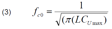
where: L – section inductance, CUmax – section capacitance for maximum voltage.
In what follows, this description will deal with the ladder line. The approximate value of the pulse rise time reduction caused by the LC ladder sections can be calculated by considering the time delay between the bottom of the amplitude and the peak of the propagating pulse as follows [9]:
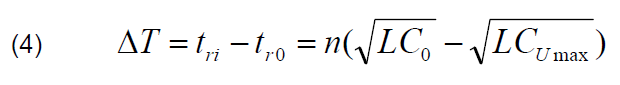
where: tri is the rise time of the input signal, tro is the rise time of the output signal, n is the number of line sections, C0 is the initial capacitance (for voltage U0=0).
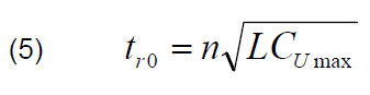
In the extreme case, the rise time of the output pulse is limited to a value corresponding to the Bragg cut-off frequency of the LC ladder.
Assuming for simplicity that only the capacitance is nonlinear and that the non-linearity is characterised by a factor k:
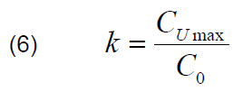
Formula (2) can be transformed into the form (7) indicating that the assumed pulse sharpening can be achieved with capacitors with weaker non-linearity if a sufficient number of n sections are used.

In the paper [4], it was shown that in practice it is easier to produce a sufficient number of oscillations (i.e. a sequence of solitons) of reasonable amplitude when the NLTL is built from 50 or more sections.
Description of the construction of a non-linear transmission line
This article describes the construction of a non-linear ladder transmission line, in which commercially available (www.tme.pl) high-voltage 2.2nF/10 kV ceramic capacitors and inductances (chokes on ring ferrite cores of NiZn type with the symbol RTNIZN 10x6x3-U1000 of dimensions Ø10/Ø6/3, made of AN-100H material with initial permeability μr=1000) were used. Due to the lack of detailed data on the physical properties of the available 2.2nF/10 kV ceramic capacitors, their capacitance as a function of voltage was determined. The results of these measurements are shown in Fig.3.

The results presented show the strong voltage dependence of the capacitance of these capacitors.
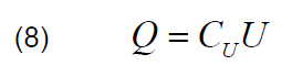
Determining additionally the electric charge accumulated in the capacitor (8), it can be seen that in the voltage range U > 2 kV the charge decreases with increasing voltage . Hence, the conclusion is that in this voltage range this capacitor will exhibit the characteristics of negative dynamic resistance
Using the ceramic capacitors discussed above, a ladder transmission line consisting of 10 LC sections was constructed according to the schematic diagram shown in Figure 4.
The high voltage pulse is applied to the line input when the TG1 controlled spark gap is triggered. The line input voltage was measured using divider R3/R4 with a division of 1000, the line output voltage was measured using divider R5/R6 with a division of 940. Measurements were carried out for capacitor C0 charging voltages between -3kV up to -6.5 kV. The view of the transmission line built and used in the study is shown in Figure 5.
Description of the laboratory tests
In the first series of tests, measurements were carried out with a line consisting of a section with parameters L=1 μH and C=2.2 nF. The voltage at the input and output of the line was recorded on a RIGOL DS4024 digital oscilloscope with a frequency response of f = 500 MHz and a sampling frequency of 4 GHz.
The pulse-solitons recorded at the line output (for a capacitor charging voltage C0 of UC0 = 3 kV) are shown in Fig. 6. There was a significant sharpening of the output pulse (from about 80 ns at the input to about 20 ns at the output) and about a 3.5-fold increase in amplitude (from 3 kV at the input to 10.5 kV at the output).
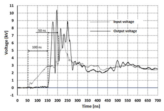
The propagation time of the pulse through the line was τ ≈ 100 ns, while the pulse reflected from the end of the line reached its input, where it was recorded, after a further 50 ns. By increasing the charging voltage to UC0 = -3.5 kV, pulses (solitons) with a maximum amplitude of 11.9 kV were recorded, as shown in Figure 7.

In the next series of tests, the choke inductance L was increased to 4 μH (doubling the number of turns) and the charging voltage of capacitor was increased to UC0 = -6 kV and UC0 = -6.5 kV.
The pulses (solitons) recorded at the line output for a charging voltage C0 of UC0 = -6 kV are shown in Figure 8, and for a charging voltage UC0 = -6.5 kV are shown in Figure 9.
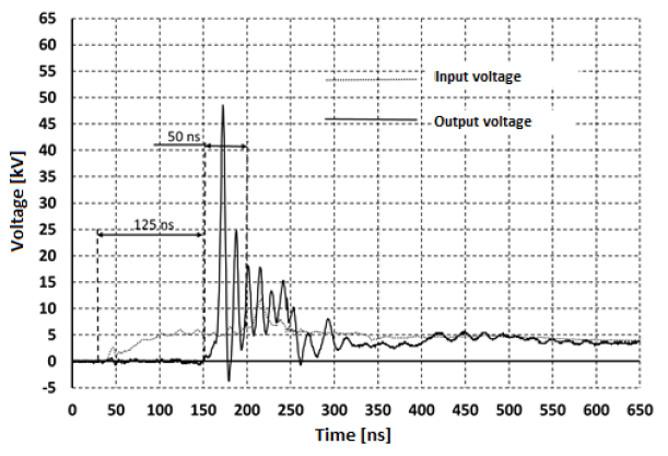
In these tests (for the case of a charging voltage value of UC0 = -6 kV), soliton pulses of surprisingly high amplitude were recorded at the output. The amplitude of the first pulse (leader) was Ul = 48 kV (i.e. an 8-fold multiplication of the amplitude was registered, from 6 kV at the input to 48 kV at the output) and with a 10-fold reduction in rise time (from 60 ns the input to 6 ns at the output). The propagation time of the wave the line was τ ≈ 125 ns, while the pulse reflected from the end of the line reached its input, where it was recorded, after a further 50 ns.


For a charging voltage of UC0 = -6.5 kV, soliton pulses with a leader amplitude of Ul = 62 kV were recorded at the output, so there was a 9.5-fold amplitude multiplication (from 6.5 kV at the input to 62 kV at the output). The propagation time of the through the line was τ ≈ 105 ns, while the pulse reflected from the end of the line reached its input, where it was recorded, after a further 46 ns.
Obtaining soliton pulses with such high voltages may be due to the fact that there is an additional, synergistic effect of the non-linearity of the ferrite chokes used. By doubling the number of turns (a 4-fold increase in choke inductance) and doubling the charging voltage of the capacitance C0, saturation of the ferrite choke cores was caused (a multiple reduction in the magnetic permeability of the choke core material).
A spectral analysis (FFT) of the soliton package generated at a capacitor C0 charging voltage of UC0 = -6.5 kV is shown in Figure 10.
Unfortunately, after four attempts, the capacitors failed. Their capacitance decreased by about 2-3 times and the character of their capacitance dependence as a function of voltage changed, as shown in Figure 11. The probable cause of the capacitors’ failure was a change in the dielectric structure at such high voltages, but the capacitors showed no breakthrough when tested with a static voltage of 12 kV!
Conclusions
1. Applying a ladder line constructed from commercially available high-voltage 2.2 nF/10kV ceramic capacitors [11] and ferrite chokes, a sequence of solitons with amplitudes ranging from 10 kV to 60 kV and half-widths of a dozen to a few nanoseconds was generated.
2. The amplitude of the solitonic output pulses was multiplied up to 9 times to 62 kV (Fig. 8), with their halfwidth of 6 ns.
3. Spectral analysis of the generated soliton parcel with a maximum amplitude of 62 kV indicates that it was dominated by a frequency of approximately 74 MHz.
REFERENCES
[1] J.D.C.DARLING, P.W. SMITH , High-power pulsed RF extraction from nonlinear lumped element transmission lines, IEEE Trans.Plasma Sci., vol. 36, no. 5 pp. 2598-2603, Oct. 2008
[2] A.J. Fairbanks, T.D. Crawford, A.L. Garner – “Nonlinear transmission line implemented as a combined pulse forming line and high power microwave source”Rev. Sci. Instrum. 92, 104702 (2021)
[3] P.W. Smith – „Pulsed, high power, RF generation from nonlinear dielectric lader networks – performance limits” Trans. of IEEE International Pulsed Power Conference 2011
[4] S. Ibuka, et. AI. – “Voltage amplification effect of nonlinear transmission lines for fast high voltage pulse generation “Trans, of IEEE International Pulsed Power Conference” 1997.
[5] R.J. Baker, et all. – “Generation of kilovolt-subnanosecond pulses using nonlinear transmission line” Meas. Sci. Technol. 4, pp 893-895, (1993).
[6] T. Kuusela, J. Hietarinta – “Nonlinear electrical transmission line as a burst generator” Rev. Sci. Instrum. 62 (9) pp 2266- 2270, September 1991
[7] M. Case et all – “Picosecond duration, large amplitude impulse generation using electrical soliton effects” Appl.Phys.Lett. Vol 60 (24), pp.3019-3021, June 1992
[8] L. P. Silva Neto, J.O.Rossi, J. J. Barroso, E. Schamiloglu – „High-power RF generation from nonlinear transmission lines with barium titanate ceramic capacitors“ IEEE Trans. Plasma Sci. 44, 3424 2016
[9] Anm Wasekul Azad – Development of puls power sources using self-sustaining nonlinear transmission lines and high-voltage solid state switches. – Dissertation in Electrical and Computer Engineering & Mathematics University of Missouri –Kansas City, 2012
[10]J. O.Rossi, P.N. Rizzo – „Study of hybrid nonlinear transmission lines for high power RF generation” IEEE Pulsed Power Conference 2009
[11] Karta katalogowa kondensatora 2,2 nF/ 10 kV – data sheet for capacitor 2,2 nF/ 10 kV – CC10K-2N2.pdf (tme.eu)
Authors: PhD, Eng Andrzej FARYŃSKI, Air Force Institute of Technology (AFIT), Księcia Bolesława 6 – street postal code: 01-494 Warsaw, post office box 96, Poland, E-mail:andrzej.farynski@itwl.pl
PhD, Eng Zbigniew ZIÓŁKOWSKI, Air Force Institute of Technology (AFIT), Księcia Bolesława 6 – street, postal code: 01-494 Warsaw, post office box96, Poland, E-mail: zbigniew.ziolkowski@itwl.pl
PhD, Eng Przemysław SUL, Warsaw University of Technology, Koszykowa Street 75, postal code: 00-662 Warsaw, Poland, E-mail: przemyslaw.sul@pw.edu.pl;
Source & Publisher Item Identifier: PRZEGLĄD ELEKTROTECHNICZNY, ISSN 0033-2097, R. 99 NR 11/2023. doi:10.15199/48.2023.11.06
