Published by Ali HAMOODI, Rasha MOHAMMED, Bashar SALIH, Northern Technical University, Engineering technical college
Abstract. The objective of this work was to protect the transmission line (T.L.) from the lightning effect. In the last decades, several methodologies have been employed for the rise of lightning performance on the T.L Lightning with high values of current is a major cause of faults. Many types of current sources (AC, DC and pulse) were simulated to represent the current of lightning and the effect of each type on a metal-oxide arrester (MOV1, MOV2) and the load. The waveform of voltages and current at the (MOV1, MOV2) and the load have been drawn. It has been concluded from the comparison among the different cases that were made.
Streszczenie. Celem tej pracy było zabezpieczenie linii przesyłowej (TL) przed wyładowaniami atmosferycznymi. W ostatnich dziesięcioleciach zastosowano kilka metodologii w celu zwiększenia wydajności wyładowań atmosferycznych w T.L. Błyskawice z wysokimi wartościami prądu są główną przyczyną usterek. Symulowano wiele rodzajów źródeł prądu (AC, DC i impulsowe), aby przedstawić prąd wyładowania atmosferycznego i wpływ każdego typu na ogranicznik z tlenku metalu (MOV1, MOV2) i obciążenie. Narysowano przebiegi napięć i prądów na (MOV1, MOV2) oraz obciążeniu. Wywnioskowano z porównania różnych spraw, które zostały przeprowadzone. (Ochrona odgromowa linii przesyłowej wysokiego napięcia za pomocą ogranicznika przepięć)
Keywords: lightning, transmission lines protection, arrestors types, metal-oxide modelling.
Słowa kluczowe: linia transmisyjna wysokiego napięcia, zabezpieczenia, ochrona odgromowa
Introduction
A lightning surge is a short-term irregular overcurrent created by lightning and momentarily applied to T.L. Lightning causes a quick shift in the electromagnetic field around T. L, resulting in an induced lightning surge. High current values are caused by lightning in the power structure, and several strategies and approaches are utilized to mitigate these challenges. Overvoltage is often of two types: fulgurite and changing [1].
The lightning strikes major electrical circuits connecting to both sides of the T.L structure, causing delays in lines and plans connected to T.L. As a result, it is critical to investigate a lightning strike for a reliable process of a control project; the discharge flow overvoltage is the key issue for the power structure and substation protection project. When lightning strikes the highest point of a transmission tower, a lightning current flows down to the lowest point of the tower and grounds; the voltage on the opposite side of the tower rises, causing a back flashover across an arc horn. Because of the considerable average return variation associated with lightning transients, a proper electrical type is necessary, and modeling investigations necessitate the whole creation of the lightning wonders and system elements. When it comes to eradicating the T.L and making preparations, lightning does the greatest damage. In electrical power networks, utilizing a surge arrestor to reduce or eliminate lightning flashovers or switching surges on distribution and transmission lines is crucial for overvoltage protection. A protection tube was an old type of surge arrestor. With the advent of the metal oxide arrester, with its superior energy capability, and with the adjustment of the quantity of earth covers, the utilization of arresters for the stronghold of lines has anticipated new energy and esteem. As a result, the flood arrestor is now in a dangerous situation where extraordinary current significance shots can keep the arrestor [2].
Effect of lightning on T.L.
When lightning strikes, it depends on a few factors: the level of the lightning represents the zone traversed by the line, the actual sizes, the general level of the line, and the presence of normally safeguarding objects, for example, structures and tall trees close to the line or different lines in a similar channel.
The total amount of lightning activity is represented by the number of lightning strikes per square mile on Earth each year. The actual line resorts to being a section that is pulled by the lightning gatherer and prompts drawing in streaks that would go after the ground distinctively over an area multiple times the width of the typical level of the above channel or protection wire .
This rationalization is typically known as an ingenious overview of a streak, understanding the width and shadow of the strains and the depth of lightning for an area, the calculation of a part of the road, the quantity, and the anticipated wide variety of moves as a result of lightning to the road in step with a mile in a year. The account wide variety will represent the everyday distribution of the statistical data, those numbers range from year to year with time and location because of the distinction within the top of the terrain and different signs and symptoms which include proximity to homes that defend the road from lightning strikes. [3].
Materials and methods
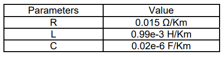
The real data of this work were taken from electric power transmission and distribution reference [4], These parameters are listed in the table (1).
Table.1 T.L parameters
The protection method used for T.L specifications, surge arresters is widely used to protect the T.L. metal oxide arrester and provide the best protection for T.L. The following components make up the fault simulation model are given as:
• Single-phase source.
• impedance.
• surge arrester (MOV1).
• T.L.
• A.C current source (represents lightning source).
• surge arrester (MOV2).
• breaker.
• parallel RLC load.
• measurements.
• scopes.
• Modern surge arrester
A metal oxide lightning arrester limits the overvoltage by means of disconnecting the road or by means of shifting to a voltage lower than the flash voltage to disconnect the road [5]. Flow dividers (surge arresters) are related on T. L with inside the center of the section and floor to sell the lightning act and to lower the fail level. Numerous special styles of arresters are accessible (e.g. with gapped or non-gapped metal-oxide) and all do in a like way, the motive is to the excessive impedance at typical operating voltages and develops low impedances via surge situations. Despite a large number of lightning arresters, they are still used with silicon carbide resistor arresters which are fixed today [6]. The simulation results show that the temporary raise in current at MOV1and MOV2 which is done by the lightning at 10kA lightning current is utilized as given in Figs.9 and10. On the other hand, a momentary rise in voltage in each arrester. After 0.03sec the arrester’s behaviour was steady state situation. the load current decreased during that time, and the load voltage increased where the lightning happens.
There are many types of lightning arresters, the two types used are metal oxide and suspension lightning arresters as shown in Fig.1 respectively. In this work, metal oxide types were adopted in the simulation.

The metal oxide device pillar, composed of the accompanying backing structure, includes the real active portion of the arrester. The pillar contains single metal -oxide resistors piled on top of apiece other, their distance conclusively defines the energy preoccupation and the current ringing ability. It is within the scope of periphery 30mm when used in the distribution system, insomuch 100mm or further for high-voltage and extra-high voltage discipline. The resistor of Metal oxide after is high between 20mm and 45mm.
Components
Metal oxide arrester consists of a saddle clamp, flex Joint, shunt, arrester body, disconnect and ground lead.
Working principle
The passing currents above the arrester in the part of the area may be useful. The voltage is very small for the power frequency so; the arrester practically makes it like an insulator. But, flow currents in the KA domain are inserted into the arrester, like in the event when lightning or swapping over-voltages happen, at that time the resultant voltage through its stations will continue low sufficient to keep the insulation of the connected appliance from the things of overvoltage. At a similar time, the escaping current runs over the arresters, this contains a big capacitive and a significantly lesser resistive section.
The function of this type of arrester is to process the system to hold off its voltage, limit the pass in voltage to a safe level with the lowest delay and filter and get the system back to its ordinary process type as soon as the passing voltage is blocked [2].
Lightning stroke machinery
When charges accumulate in clouds, the lightning process occurs, as the charges are discharged into neighbouring clouds or to the ground. Basically, the process of the occurrence of lightning is an electric discharge of charges in the form of flashes from clouds with positive and negative charges. Charges in the cloud as given in Fig.2 pass when the lesser Part of the cloud is negatively charged at a temperature of -5°C although the positive charge is located at the top of the cloud at a temperature below -200C.
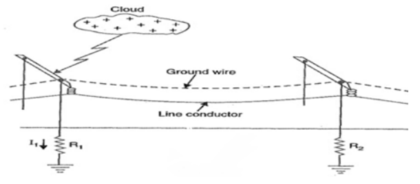
Below the cloud, it is possible to form positive charges on the ground. In most thunderclouds, there is an area with limited positive grime located near the bottom of the cloud a 0°C. Charges formed in the kilo-coulomb range reaching a distance of about 50Km will be formed when lightning occurs, but the average current discharged by lightning is within limits KA [7]. The effect of lightning is the effect of a dense current of high strength and it increases first in the atmosphere, then in the solid state, or less at (the earth) [8- 10].
Lightning parameters
Lightning arrester is considered as the primary source for designing lightning protection devices to reduce over voltage on a transmission line. These parameters are given as:
• Peak current value of both first and subsequent
• Stroke current wave shape
The size of the stroke charge and the magnitude of the return strike are key qualities to study the ultimate lightning force on the head of the T.L system.
There are two types of lightning strokes:
• Direct lightning strokes
Direct lightning stroke finishing on the T.L may affect in the happening that intrudes the power method, such as the above voltage. The lightning overvoltage is observed as the main reason for line isolation flashover, which can be separated into three types specifically back flashover, protecting failure and persuaded overvoltage [11-12].
• Indirect lightning strokes
Encouraged overvoltage happens when a clouds-to-earth lightning flashes crops a passing electromagnetic field, so makes important surge voltage on overhead lines in the area. The lightning-persuade overvoltage is in charge of the common errors occurring in circulation overhead lines. Though, these made voltages have an unimportant result on high-voltage T.Ls. The voltage motivates on a T.L affected by a secondary lightning stroke normally contains four main parts [13-15].
Proposed model
A 735kV transmission system with two T.L arresters located at the sending and the receiving ends of the line feeds a load (8MW) through a 16.093 Km T.L as given in Fig.3. Over the system a lightning surge of (10kA,20kA,30kA) was tempted and the simulation results were carried out by using MATLAB software environment.

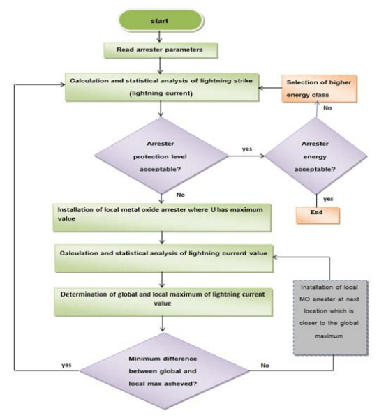
Algorithm flowchart template
In order to fulfil the scope of this work, the development process ode23t(mod/Trapezoidal) simulation of a metal oxide surge arrester on a 735 kV T.L is applied. The process flow of the modelling system with a details explanation is illustrated in Fig.4.
Results and discussion
Before the fault occurred, the simulation results showed the temporary putting-up in current at MOV1 and MOV2 after applying different lighting current values as illustrated in Fig.9 and Fig.10. In addition to the temporary increase in both arrester’s voltages. After fault at time 0.03 sec, the two arrester’s behaviour as steady state conditions but the load voltage has been increased as compared with the load current that decreased.
Ac current source (lightning source) At lightening surge (10kA) (Ac surge)
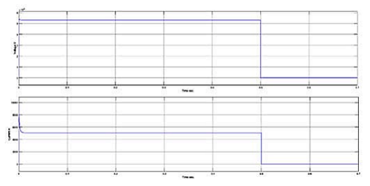
Fig. 5-6 represents the relationship between voltage and current with respect to time at MOV1and MOV2.


Fig. 7 represents the relationship between voltage and current with respect to time at load.


DC current source (lightning source) At lightning surge (10kA) (DC surge)
Fig. 8-9 represent the relationship between voltage and current with respect to time at MOV1and MOV2.
Fig. 10 represents the relationship between voltage and current with respect to time at load.
At lightning surge (10kA) (pulse surge) Fig. 11-13 represents the relationship between voltage and current with respect to time at MOV1and MOV2.
Fig.13 represents the relationship between voltage and current with respect to time at load.


Before the breaker (fault) switch is open i.e. before the fault occurred time the current passed into MOV1and MOV2 and no current appeared at load because the arresters (MOV1&MOV2) behaviour as non-linear resistance, in this case they behave as low resistance and the lightning current (10 KA) passed through them to the ground, no current signal appeared at load for all causes (AC, DC and Pulse) current surge.
Conclusions
After applying many different current sources on T.L many cases are appeared and they gave various conclusions as follows: From AC current source Fig. 5 and 6 show that after fault accrued, the voltage at MOV1 was lower than that at MOV2, but the current at MOV1 was higher than the current at MOV2. Fig. 8 and 9, show that after fault accrued, the voltage at MOV1 is approximately equal to the voltage at MOV2, and the current at MOV1 and MOV2 settled at zero. For the impedance of T.L, the current rating of the arrester and discharge voltage are 10KA and 30KV. This work will give and help the knowledge about the overvoltage of the protection system for T.L supported by the surge arrester. DC and pulse surges gave voltage at MOV1 higher than that generated by AC surge. AC surge gave voltage at MOV2 higher than that generated by booth DC and pulse surges. At 10KA (AC surge) Before fault occurrence, the voltage and current at MOV1 were lower than that at MOV2, but at load, the voltage reduced to zero and the current jumped instantaneously to (5250e7 ) due to the effect of impedance. The peak impulse voltage of the load current when the breaker has been closed appeared approximately equal for AC, DC and pulse surges.
Acknowledgments: We would like to thank our affiliation with the northern technical university (NTU) for supporting us in our work.
REFERENCES
[1] Gaurav S, Anshul M. Simulation of Compensated T. L Protection from Lightning by Using Matlab. IJERT. 2015; 4 (5): 146-149.
[2] Chaitrashree SR, Sahana S, Rajalakshmi PM, Noor A. Analysis of the Use of Surge Arresters in Transmission System Using MATLAB/Simulink. IJAREEIE. 2016; 5(3):1428-1434.
[3] M. G. Comber, S.F. LaCasse, R.M. Reedy, “Lightning Protection of T.Ls with Polymer-Housed Surge Arresters”, presented at EEI T&D Meeting Palm Beach, FL May 18, 1994.
[4] S Satyanarayana, S.Sivangaraju, “Electric Power Transmission and Distribution” Pearson Education India, 2008.
[5] Jaroszewski M, Pospieszna J, Ranachowski P, Rejmund F. Modeling of Overhead Transmission Lines with Line Surge Arresters for Lightning Overvoltages. Application of Line Surge Arresters in Power Distribution and Transmission Systems, Cavtat .2008;18(1):120-131
[6] Nangkyuthini K. Lightning Performance of Medium Voltage T.L Protected by Surge Arresters. An International Journal of Scientific Engineering and Technology Research. 2008; 3(16) :3362-3367.
[7] Moe MS, Naung CW. T Lightning Performance of Medium Voltage T.L Protected by Surge Arresters International Journal of Research Publications.2014;3(16):3362-3367
[8] Sanketa S. Lightning Phenomenon, Effects and Protection of Structures from Lightning. IOSR-JEEE. 2016; 11(3): 44-50.
[9] Santosh BK, Rajan HC. MATLAB/SIMULINK Simulation Tool for Power Systems” International Journal of Power System Operation and Energy Management. 2011;1(2): 2231 4407
[10 ] Safwan AH, Farah IH, Ali NH. Pitch Angle Control of Wind Turbine Using Adaptive Fuzzy-PID Controller. EAI Endorsed Transactions on Energy. 2020; 7 (28): 1-8
[11] Safwan AH, Ali NH, Ghanim MH. Automated irrigation system based on soil moisture using arduino board. Bulletin of Electrical Engineering and Informatics.2020 ; 9(3): 870-876.
[12] Ali NH, Safwan AH, Rasha AM. Photovoltaic Modeling and Effecting of Temperature and Irradiation on I-V and P-V Characteristics. International Journal of Applied Engineering Research. 2018; 13(5): 3123-3127.
[13] Ali NH, Safwan AH, Ahmmed GA. Photovoltaic-Battery System Tested under Sun Irradiance. LJER. .2018; 18( 2):65- 75. Ali NH, Safwan AH, Mohammed AI. Power Factor Correction [14] of AC to DC Converter Using Boost Chopper. J Appl Sci Eng. 2018; 13 (8): 6440-6445.
[15] Rasha AM, Ali NH, Bashar MS. Partial discharge measurement in solid dielectric of H.V Cross-linked polyethylene (XLPE) submarine cable. Indonesian Journal of Electrical Engineering and Computer Science.2020; 17(3): 1578-1583.
AUTHORS: Ali N. Hamoodi, Northern Technical University (NTU), E-mail: ali_n_hamoodi@ntu.edu.iq.
Rasha A. Mohammed, Northern Technical University (NTU), Email: rasha8479@ntu.edu.iq.
Bashar M. Salih, Northern Technical University (NTU), E-mail: basharms_tecm@ntu.edu.iq.
Source & Publisher Item Identifier: PRZEGLĄD ELEKTROTECHNICZNY, ISSN 0033-2097, R. 99 NR 2/2023. doi:10.15199/48.2023.02.21
