Published by Ivan KOSTIUKOV, National Technical University “Kharkiv Polytechnic Institute”, Department of Electrical Insulation and Cable Engineering, Ukraine
Abstract. This paper gives a description of measurement method which can be used in practice of carrying out measurement of stray inductance of tested capacitive object with the unknown value of electrical capacitance. Stray inductance is determined by means of analysis of previously smoothed by the least squares method curves of discharge current caused by overdamped discharge of tested capacitive object. An example of practical implementation and the analysis of factors that affect the accuracy of proposed method are also given.
Streszczenie. W artykule opisano metodę pomiarową, która może być zastosowana w praktyce do pomiaru indukcyjności rozproszonej badanego obiektu pojemnościowego przy nieznanej wartości pojemności. Indukcyjność rozproszoną wyznacza się na podstawie analizy wygładzonych wcześniej metodą najmniejszych kwadratów krzywych prądu wyładowania wywołanego rozładowaniem badanego obiektu pojemnościowego. (Oszacowanie indukcyjności rozproszonej kondensatorów na podstawie analizy prądów rozładowania)
Keywords: correlation coefficient, dielectric permittivity, insulation testing, voltage drop.
Słowa kluczowe: indukcyjność roz[proszona, kondensator, prąd rozładowania
Introduction
The value of electrical capacitance is among various other factors that can cause a significant impact on technical performance of high voltage equipment, which is used in electrical engineering. Due to the dependence on the value of relative dielectric permittivity, this characteristic of electrical insulation is quite sensitive to the presence of humidity [1]. Therefore, the values of electrical capacitance and dielectric permittivity can be efficiently used in various practical applications which require the assessment of quality of electrical insulation [2-4]. Besides, the value of electrical capacitance is among other factors that influence the value of power losses in insulation of electrical equipment [5]. In practice the problem of electrical capacitance measurement can be solved by applying various technical solutions. Numerous methods of measurement are based on the applying of AC bridges, for example Schering bridge [6]. Another wide spread approach for electrical capacitance measurement implies the determination of time constant of the discharge process [7]. Some other research, focused on electrical capacitance and impedance measurement, have been concentrated on the development of measurement techniques based on the applying of quasi-balanced circuits [8], schemes with phase detectors [9], measurement schemes which imply the applying of various techniques for digital signal processing [10], applying of impedance–to-voltage converters [11], as well as specialized integrated circuit AD5933 [12].
In majority of cases the analysis of technical performance of measurement schemes is carried out under the assumption of negligible impact of parasitic parameters of tested object on their technical performance. However, in case if it is necessary to carry out the assessment of technical state of electrical insulation which operates in high voltage equipment, the presence of some inevitable stray inductance of tested object often can lead to certain difficulties in physical interpretation of the obtained results. Despite the efforts devoted to solving the problem of stray inductance mitigation, it affects some regimes of operations even for such almost entirely capacitive objects as various types of electrical capacitors [13-15] and capacitive voltage dividers [16]. Mentioned difficulties are caused by the fact that the inevitable stray inductance of tested object in some regimes of measurement can cause the increasing of measured values of electrical capacitance with the increasing of frequency of applied voltage. As the increasing of frequency of applied voltage usually leads to more or less distinct decreasing of relative dielectric permittivity, depending on specific types of polarization valid for a particular dielectric material, such increasing of electrical capacitance complicates physical interpretation of the obtained results of measurement. The increasing of electrical capacitance usually becomes more significant in case when frequency of applied voltage approaches the resonant frequency of tested object, i.e. with the increasing of frequency of applied voltage. Besides mentioned difficulties in physical interpretation of obtained results of electrical capacitance measurements, it is obvious that the presence of stray inductance inevitably causes certain difficulties in the assessment of the dielectric dissipation factor. In case of negligible stray inductance of tested object and parallel equivalent scheme of tested capacitive object with power losses the value of dissipation factor can be determined according to the usual relation:
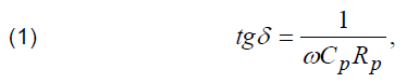
where: ω is the value of angular frequency of applied voltage, Cp, Rp are the values of electrical capacitance of tested object and shunt resistance caused by power losses. As it can be concluded from (1), possible inaccuracy of carried out measurements of Cp, Rp caused by the presence of stray inductance results in inaccuracy of dissipation factor measurements. Consequently, the presence of some stray inductance of tested capacitive object can distort the results of measurements and causes misconceptions about the technical state of tested object. Therefore, for practical applications it is necessary to develop methods of measurements which can be used in order to carry out the assessment of stray inductance of tested capacitive object.
The problem of stray inductance estimation is actual not only in issues that concern the assessment of quality of electrical insulation, but also for other practical applications of electrical engineering, such as the formation of high values of current pulses with specified requirements to their time dependence. The inductance of the discharge circuit affects time dependence of current pulses [17] and, therefore, this time dependence is also affected by the additional contribution caused by the stray inductance of storage capacitor.
The objective of this paper is the elaboration of method for the estimation of stray inductance of tested capacitive object, based on the analysis of transients in electrical circuits that occur due to the overdamped discharge of tested capacitance.
Illustration of the affect of stray inductance on the accuracy of electrical capacitance measurement
Fig. 1 presents the results of carried out measurements of electrical capacitance of a batch of high voltage pulse capacitors with nominal value of capacitance equal to 140 μF and operating voltage equal to 5 kV. All measurements have been carried out by applying series equivalent scheme of tested capacitor with power losses and by means of using digital DE-5000 RLC meter.
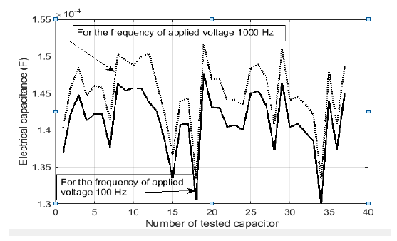
Fig.2 represents the increment of electrical capacitance caused by the increasing of frequency of applied voltage from 100 Hz to 1000 Hz.
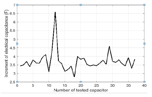
From Fig.2 it can be seen that the increasing of frequency of applied voltage leads to previously mentioned increasing of electrical capacitance, which can be noticed for any of tested high voltage capacitors. It is obvious that for the case of unknown values of stray inductance of tested capacitor, shunt resistance, caused by dielectric power losses, and also for the unknown value of electrical capacitance, which can be affected by the presence of moisture, such increasing of electrical capacitance complicates physical interpretation of obtained results of measurements, as it contradicts the admissible dependence of the relative dielectric permittivity on frequency of applied voltage.
Materials and methods
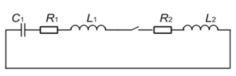
Elaborated method for the estimation of stray inductance is based on the analysis of discharge current curves for the overdamped discharge regime of tested capacitive object. All discharge processes have been considered for the case of the equivalent scheme of the discharge circuit presented on Fig. 3, which is pretty typical for example in practice of modelling discharge processes in generators of pulse currents with high voltage pulse capacitors.
As it can be seen from Fig. 1, the presence of parasitic parameters of tested object L1 and R1 disenables the direct measurements of voltage on an unknown capacitance.
However, in practice it is possible to measure the value of voltage drop on the outputs of current to voltage converter, represented by resistance R2 on Fig. 2. Assuming negligible inductance of discharge circuit L2, this voltage can be represented as a sum of voltages on the unknown electrical capacitance, stray inductance and resistance, caused by power losses in tested object:
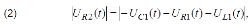
where UC1(t), UR1(t) and UL1(t) respectively denote the values of voltage drop on the unknown capacitance, power loss resistance of tested object and stray inductance of tested object.
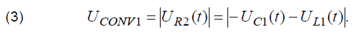
In this case it is necessary to consider two cases that correspond to different ratios between the values of R2 and R1.The first case corresponds to the insignificant resistance caused by power losses in tested object. In this simplest case it is possible to assume that the value of voltage on R2 in each moment of transient is equal to the sum of voltages on capacitance and stray inductance. In this case it is possible to neglect with the value of voltage on R1 and the value of voltage on the output of current-to-voltage converter UCONV1 can be written as:
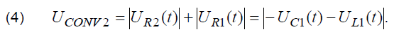
The second case corresponds to the significant value of the internal resistance R1. In this case in is necessary to carry out measurements of R1 and make appropriate processing of obtained oscillograms in order to obtain the array of data which is determined only by the values of voltage drop on stray inductance and measured capacitance. In this case the value of voltage on the output of current-to-voltage converter UCONV2 can be written as:
Hence, in both cases processed time dependence of voltage is determined by the value of voltage drop on measured capacitance and stray inductance. In order to carry out measurement of stray inductance it is necessary to distinguish the exact contribution of each of these components to their sum, which is available for measurements.
Separation of component of voltage drop on stray inductance of tested object from the component of voltage drop on the unknown capacitance can be carried out by considering the relation which determines correlational relationships between signals.
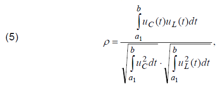
where ρ denotes the value of correlation coefficient, uC(t) and uL(t) respectively denote time dependencies of voltage on measured capacitance and stray inductance. The upper boundary of integration b corresponds to the instant of transient termination, while the lower boundary of integration a1 varies in a range of values that correspond to time interval from the beginning of transient to the value of Tc, which can be determined according to:
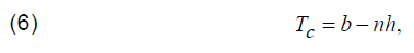
where h denotes time duration between two samples of analyzed signal, n is arbitrarily selected integer number.
Subsequent analysis and calculations according to (5) will be carried out by using the following relations (7-9) for the discharge current [18]:
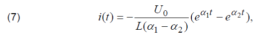
where U0 is the initial value of voltage on measured capacitance and α1, α2 can be determined by using the following relations: where U0 is the initial value of voltage on measured capacitance and α1, α2 can be determined by using the following relations:
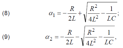
where L is the total inductance of the discharge circuit, R is total value of resistance of the discharge circuit that includes both values of R1 and R2:

Further analysis also will be carried out for the case when the parameters of the discharge circuit satisfy the relation which allows to consider that |α1| << |α2|. Fig. 4 presents the results of carried out according to (5) calculations. All calculations have been carried out for the value of C1 equal to 4.7·10-6 F and L1 + L2 equal to 15·10-2 H.
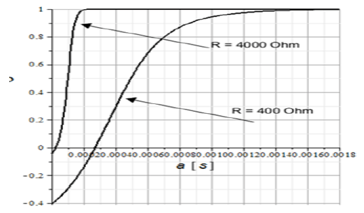
As it can be seen from Fig. 4, the increasing of lower boundary of integration leads to the increasing of ρ, which reaches 1 and stays invariable for higher values of a1. Such tendency becomes more distinct with the increasing of resistance of the discharge circuit. For the region with ρ equal to 1 it is rather difficult to distinguish the exact contribution of voltage drop on stray inductance and capacitance to their sum, which is available for measurements. However, for the value of ρ equal to 0 such separation can be carried out by using the orthogonality of analyzed signals. In order to carry out such separation of components of voltage drop, (4) should be written in the following form:
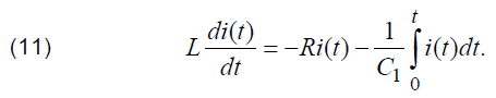
The value of stray inductance, similalry to the values of voltage drop on these elements of equivalent scheme on Fig. 3, can be determined by means of multiplying (11) on time derivative taken from time dependence of the discharge current and by making integration from previously determined according to (5) value of the lower boundary of integration a1, which corresponds to zero value of (5), to the value of b, which corresponds to the moment of transient termination. In this case it can be noticed that due to the absence of correlation between the corresponding time dependencies of voltage drop the second term in the right side of (11) is equal to 0. Consequently, in this case (11) can be reduced to the following relation:
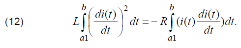
By taking into consideration (12), the value of stray inductance can be determined as:

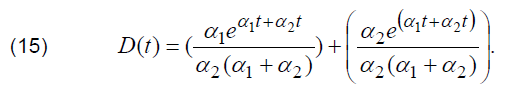
As the absence of correlation between time dependencies of voltage drop on stray inductance and measured capacitance is essential for making calculations according to (13), comprehensive description of proposed method should include the analysis of conditions for which the value of calculated according to (5) correlation coefficient is equal to zero. The upper boundary of integration b in (5) corresponds to the moment of transient termination and, therefore, antiderivative function for the numerator of (5) is equal to zero for the moment of time b. Consequently, it is sufficient to carry out such analysis only for time dependence of antiderivative function in the numerator of (5). This antiderivative function can be written in the following form:
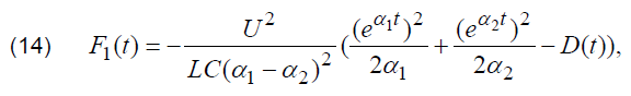
where D(t) can be determined by the following relation:
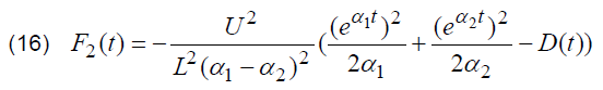
It is necessary to emphasize that all the results of calculations presented on Fig. 4 have been carried out for the values of voltage drop on electrical capacitance (uC(t)) and stray inductance (uL(t)) of tested object. However, due to the presence of parasitic parameters L1 and R1 of capacitive object the exact value of voltage on capacitance which is used in (5) is unavailable for direct measurements. The same problem is valid for the value of voltage drop on stray inductance. Therefore, both time dependencies of voltage drop, which are necessary for carrying out calculations according to (5), are unavailable for direct measurements. Nevertheless, it can be shown that for practical calculations it is sufficient to carry out the assessment of lower boundary of integration a1, that corresponds to zero value of (5), without taking into consideration the exact values of voltage drop on stray inductance and by processing only experimentally obtained curves of the discharge current. As time dependence of the discharge current is available for direct measurements, the determination of the lower boundary of integration a1 can be carried out by the analysis of antiderivative, determined for the result of multiplication of time derivative for the discharge current and antiderivative for the discharge current. This antiderivative function can be determined according to (16):
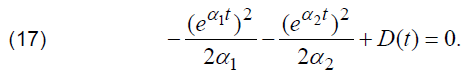
As it can be noticed, (15) and (16) have different denominators. Nevertheless, mentioned difference does not affect the accuracy of a1 determination, as for both cases of F1(t) and F2(t) the value of a1 will be obtained as a root of the following relation:
Consequently, instead of determination of a1 by applying the root of determined according to (14) function F1(t), which implies the applying of values of voltage on stray inductance and capacitance which are unavailable for direct measurements, the value of a1 can be efficiently determined by finding the root of F2(t).
Calculation of stray inductance according to (13) requires the determination of time derivative for the discharge current. Therefore, it should be taken into consideration that in case of processing of digital signals by means of various numeric methods, for example by the finite differences method, even small perturbations in sampled signal will result in a pretty significant perturbations in calculated time derivative. Therefore, in practice it is preferable to process previously smoothed curves by applying the least squares method with the help of the following relation:
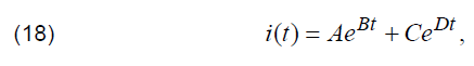
where A, B, C, D are coefficients, determined by means of applying the least squares method. Therefore, for smoothed by the least squares waveform of the discharge current previously mentioned antiderivative determined for the result of multiplication of time derivative for the discharge current and antiderivative for the discharge current can be written as:

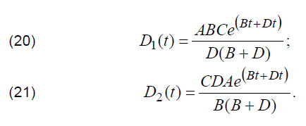
where D1(t) and D2(t) can be determined according to (20, 21):
By taking into consideration (19), the relation for a1, for the case of processing curves of current previously smoothed by the least squares, can be written according to:
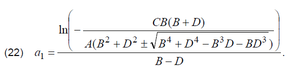
As the values of coefficients A, B, C and D are derived after the processing of experimentally obtained curves of discharge current, in further analysis (22) will be used for the experimental determination of a1,
The results of practical implementation of described method
The described method for electrical capacitance measurement was substantiated by the analysis of discharge current curve that arises due to the overdamped discharge of 4.737 μF polypropylene capacitor. Stray inductance of tested object was imitated by series connection of a cylindrical air core coil to the tested capacitor. Equivalent parameters of the discharge circuit which have been used for the substantiation of described method are presented in Table 1.
Table 1. Parameters of the discharge circuit
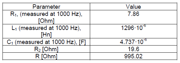
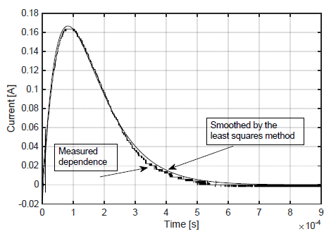
Fig. 5 presents measured and smoothed by the least squares method waveform of the discharge current, which was analysed in order to carry out calculation of stray inductance according to (13).
The results of processing of presented on Fig. 5 curve of the discharge current are presented in Table 2.
Table 2. The results of processing curve of the discharge current
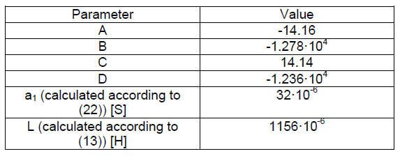
The comparison of presented in Table 2 results of calculations with the value of stray inductance presented in Table 1 shows that presented approach for processing curves of discharge current allowed to attain the sufficient level of accuracy, as the discrepancy between the presented in Table 1 value of stray inductance and estimated according to (14) and presented in Table 2 value of stray inductance was 140·10-6 Hn with a relative error of estimation equal to 11%. Among other various factors, in this case the inaccuracy of estimation could have been caused by a not very properly adjusted regime of capacitors discharge. For the parameters of discharge circuit presented in Table 1 calculated according to (8, 9) complex coefficients α1 and α2 indicate that the regime of capacitors discharge was underdamped, though it was pretty close to overdamped, as indicates time dependence of the discharge current presented on Fig. 5
Remarks on some factors that affect the accuracy of described method
The accuracy of the described method, obviously, is affected by the accuracy of determination of the lower boundary of integration a1, for which (5) is equal to zero. This conclusion arises due to the fact that the relation for stray inductance (13) was obtained under the assumption that time dependence of voltage drop on stray inductance is orthogonal to time dependence of voltage drop on electrical capacitance, which is valid only for certain value of a1. Therefore, it is necessary to emphasis opposite requirements that arise to the value of R2 from the point of view of more accurate determination of the lower boundary of integration a1, and more accurate determination of total resistance of the discharge circuit R, which is used in (13). In practice the value of R1, obviously, is affected by its possible more or less distinct frequency dependence. For overdamped discharge of tested capacitance C1 curves of the discharge current can be characterized by spectral density distributed in a pretty broad range of frequencies Therefore, it is quite difficult to accurately assess the exact value of the resistance R1 caused by power losses in conductive parts of tested capacitive object. In practice the most efficient way to eliminate the influence of R1 on accuracy of measurements is the increasing of R2, as insignificant values of R1 in comparison with R2 allow not to take this value into the consideration. However, as it can be distinctly seen from data on Fig. 4 this very requirement leads to the decreasing of the lower boundary of integration a1 for which (5) is equal to zero, and, therefore, causes additional difficulties for accurate determination of a1. The accuracy of stray inductance estimation can be also affected by time the dependencies of inductive elements on the equivalent scheme on Fig. 2 that can arise due to the impact of skin-effect. Such time dependencies have not been taken into consideration in proposed method of processing curves of the discharge current, as all relations have been obtained under the assumption of invariable in time parameters of the equivalent scheme on Fig. 3. As switching elements affect time dependence of the discharge current, special attention should be paid to the proper selection of switching elements of the discharge circuit The distortion of current curve can degrade the accuracy of determination of a1 and, therefore, can lead to additional inaccuracy in measurements of stray inductance.
Conclusions
Described method for the estimation of stray inductance is based on the analysis of discharge current curves for overdamped discharge of tested capacitive object. As due to the presence of parasitic parameters the value of voltage on tested capacitance is unavailable for direct measurements, analyzed curves are derived from the value of voltage drop on the output of current-to-voltage converter. This value is equal to the sum of voltages on stray inductance and electrical capacitance. Separation of mentioned components of voltage drop is achieved by the determination of zero value of correlation coefficient between time dependencies of time derivative and primitive function for discharge current. An example of practical implementation of the described method has shown a sufficient for some applications level of accuracy.
REFERENCES
[1] Ozaki T. , I to N. , Nakamura S, Kawai J Changes in capacitance and dielectric dissipation factor of water-treed XLPE with applied voltage, Electrical Engineering in Japan, 144 (2003), No. 1, 12-20.
[2] Fothergi l l J.C., L iu T., Dodd S.J., Dissado L.A., Nilsson U.H. The measurement of very low conductivity and dielectric loss in XLPE cables: a possible method to detect degradation due to thermal aging IEEE Transactions on Dielectrics and Electrical Insulation, 18 (2011), No. 5, 1544-1553.
[3] Zaengl W.S. Dielectric spectroscopy in time and frequency domain for HV power equipment, part 1: Theoretical Considerations, IEEE Electrical Insulation Magazine, 19 (2003), No. 5, 5-19
[4] Younsi K., Neti P., Shah M., Yingneng Zhou J., Krahn J., Weeber K. Online capacitance and dissipation factor monitoring of AC motor stator insulation, IEEE Transactions on Dielectrics and Electrical Insulation, 17 (2010), No. 5, 1441-1452
[5] Kropotin O., Tkachenko V., Shepelev A., Petrova E., Goryunov V., Bigun A. Mathematical model of XLPE insulated cable power line with underground installation, Przegląd Elektrotechniczny, 95 (2019), No. 6, 77-80
[6] Bera S.C., Chattopadhyay S. A modified Shering bridge for measurement of the dielectric parameters of a material and the capacitance of a capacitive transducer, Measurement, 33 (2003), No. 1, 3-7
[7] Rathore T.S. A novel backlash circuit and scheme for capacitance measurement IETE Technical Review, (1984), No.1, 110
[8] Roj J., C ichy A. Method of measurement of capacitance and dielectric loss factor using artificial neural networks, Measurement Science Review, 15 (2015), No. 3, 127-131
[9] Raven M.S. , Raven D. New approaches to the direct measurement of capacitance, Electrocomponent Science and Technology, 4 (1977), No. 1, 37-42
[10] Ramos P.M. , Janei ro F. M. , Radi l T. Comparison of impedance measurements in a DSP using ellipse-fit and seven parameter sine-fit algorithms, Measurement, 42, (2009), No. 9, 1370-1379.
[11] Shijie Sun, Lijun Xu, Zhang Cao, Hai l i Zhou and Wuqiang Yang. A high-speed electrical impedance measurement circuit based on information-filtering demodulation, Measurement Science and Technology, 25 (2014), No. 7, 075010,
[12] Chabowski K., Piasecki T., Dzierka A. Simple wide frequency range impedance meter based on AD5933 integrated circuit, Metrology and Measurement Systems, 22 (2015), No. 1, 13-24,
[13] Siami S., Daude N., Joubert Ch., Merle P. Minimization of the stray inductance in metalized capacitors: Connections and winding geometry dependence, The European Physical Journal Applied Physics, 4 (1998), No. 1, 37-43
[14] Ingal ls M. , Kent G. Monolithic capacitors as transmission lines, IEEE Transactions on Microwave Theory and Techniques, MTT-35 (1987), No. 11, 964-970
[15] Joubert Ch., Beroual A ., Rojat G. Magnetic field and current distribution in metalized capacitors, Journal of Applied Physics, 76 (1994), No. 9, 37-43
[16] Wong, C.S . Effect of stray inductance on capacitive voltage divider, IEEE Journal of Applied Physics, 56 (1986), No. 2, 673-675
[17] Patry I., Nicola M., Marinescu C., Vladoi L., Nitu M. , C. Achievement of current pulses of high amplitude using a voltage pulse generator, Annals of the University of Crainova, Electrical Engineering series, 43 (2019), No. 1, 71-78.
[18] Neiman L .R. , Demi r chjan K.S. Theoretical foundations of electrical engineering, Part 1, Leningrad, 1959.(in Russisn)
Author: PhD Ivan Kostiukov, National Technical University “Kharkiv Polytechnic Institute”, 2, Department of Electrical Insulation and Cable Engineering Kyrpychova str.,61002, Kharkiv, Ukraine E-mail: iakostiukow@gmail.com.
Source & Publisher Item Identifier: PRZEGLĄD ELEKTROTECHNICZNY, ISSN 0033-2097, R. 97 NR 4/2021. doi:10.15199/48.2021.04.32
