Published by SARAGADAM HEMANTH KUMAR, SH SURESH KUMAR BUDI, Dept. of EEE, Gokul Group of Institutions, Piridi, Bobbili, AP, India.
Abstract: Voltage sag is one of the most common power quality disturbances in electrical networks. Voltage sags are incidents that reduce the voltage amplitude for a short time. Voltage Sags are caused by abrupt increases in loads such as short circuits or faults, motor starting, or electric heaters turning on, or they are caused by abrupt increases in source impedance, typically caused by a loose connection, so the power quality reduces. To prevent these voltage sags a new topology of Fault Current Limiter (FCL) is proposed for the voltage sag and the phase-angle jump mitigation of the substation Point of Common Coupling (PCC) after fault occurrence. This structure has a simple control method. By using the semiconductor switch in the dc current path instead of two numbers of thyristors at the bridge branches, the FCL has high speed and consequently, the dc reactor value is reduced to a lower value. Using the dc voltage source in the proposed structure compensates the voltage drop on the powerelectronic devices and the small dc reactor resistance. In addition, the dc voltage source placed in the proposed FCL structure reduces its Total Harmonic Distortion (THD) and ac losses in normal operation. In general, this type of FCL, with the simple control circuit and low cost, is useful for the voltage-quality improvement because of voltage sag and phase-angle jump mitigating and low harmonic distortion in distribution systems. So it reduces the THD of the voltage waveform on load voltage and it has low ac losses in normal operation. In this project voltage sag compensation by using FCL is designed in MATLAB/Simulink software and simulation results are presented. In this project single phase and three phase with and without FCL Simulink models are proposed and their behaviors are observed.
Keywords: Fault Current Limiter (FCL), Point of Common Coupling (PCC), Total Harmonic Distortion (THD).
I. INTRODUCTION
In an effort to prevent damage to existing power-system equipment and to reduce customer downtime, protection engineers and utility planners have developed elaborate schemes to detect fault currents and activate isolation devices (circuit breakers) that interrupt the over-current sufficiently rapidly to avoid damage to parts of the power grid. While these traditional protection methods are effective, the ever-increasing levels of fault current will soon exceed the interruption capabilities of existing devices. Shunt reactors (inductors) are used in many cases to decrease fault current. These devices have a fixed impedance so they introduce a continuous load, which reduces system efficiency and in some cases can impair system stability. Fault current limiters (FCLs) and fault current controllers (FCCs) with the capability of rapidly increasing their impedance, and thus limiting high fault currents are being developed. These devices have the promise of controlling fault currents to levels where conventional protection equipment can operate safely. A significant advantage of proposed FCL technologies is the ability to remain virtually invisible to the grid under nominal operation, introducing negligible impedance in the power system until a fault event occurs. Ideally, once the limiting action is no longer needed, an FCL quickly returns to its nominal low impedance state.

Fig.1 shows the diagram of a test system used in this paper. The low voltage side of the substation transformer is Y-connected and is grounded by means of a reactor of 0.01 per phase. This grounding system limits over currents caused by single-phase-to-ground faults. The high voltage side of the substation transformer is _- connected. At MV and LV sides of transformer, single phase- to-ground fault (LG), two-phase- to-ground fault (2LG), two-phase fault (2L) and three-phase fault (3L) will be examined and the results can be evaluated. The probabilities of each type of faults are as follows: LG = 75%, 2LG = 17%, 3LG = 3%, 2L = 3%, 3L = 2%.
Thus, single-phase-to-ground fault and two-phase-to ground fault will be considered further. The results (voltage-time curve) are shown in Fig.2. to 2.8 The results of operations performed by the procedure implemented in MATLAB can be summarized as follows.
• The retained voltage during a three-phase fault at the secondary of the substation can be approximated by means of the following expression:

Where ZS and ZTR are, respectively the impedances of the high-voltage (HV) equivalent and the substation transformer; Rf is the fault resistance, while V(pre-sag) and V(sag) are the voltages prior and during the fault, respectively. This formula shows that if the impedance of substation transformer is large enough, with a low fault resistance, not many equipment trips should be caused by three-phase faults (Math and Bollen, 1996; Caldron et al., 2000).
• If customer equipment is installed only at the low voltage side, as assumed in this work, the percentage of trips due to single-phase-to-ground faults will significantly decrease.
• Depending on the distribution voltage level and the transformer grounding system, only those faults originating not far from the substation terminals will cause severe voltage sags.
• Type of transformer influence on type of voltage sag at MV side of transformer is significant and can increase or decrease the voltage of different phases during the fault.

According to IEEE standard 1159-1995, a voltage sag is defined as a decrease to between 0.1 and 0.9 p.u. in root mean square (rms) voltage at the power frequency for durations of 0.5 cycle to 1 min [1]. Voltage sags have always been present in power systems, but only during the past decades have customers become more aware of the inconvenience caused by them. A power system fault is a typical cause of a voltage sag [2]. Faults occur in transmission (EHV), sub transmission (HV), medium-voltage (MV), and low-voltage (LV) systems, and the sags propagate throughout the power system. The sag distribution experienced by a low-voltage customer includes all these sags of different origin. It is not essential that all power system areas are modeled and included in voltage sag distribution calculations. This issue is studied in this paper. In addition, voltage sag distributions are calculated for two urban and two rural power system areas. The sag propagation throughout the power system and the probabilities of different fault types at each voltage level are taken into account in the calculations. Voltage sags can generally be characterized by sag magnitude, duration, and frequency [3]. Network impedances determine the sag magnitude. When considering sags caused by faults, the protection practices specify the sag duration, and the fault frequencies determine the number of voltage sags.
II. PROPOSED METHOD
Electric power quality (PQ) can be defined as the capacity of an electric power system to supply electric energy of a load in an acceptable quality. Many problems can result from poor PQ, especially in today’s complex power systems, such as the false operation of modern control systems. Voltage sag is an important PQ problem because of sensitive loads growth. Worldwide experience has show that short-circuit faults are the main origin of voltage sags and, therefore, there is a loss of voltage quality. This problem appears especially in buses which are connected to radial feeders. The most common compensator for voltage sag is the dynamic voltage restorer (DVR). The basic operation of the DVR is based on injection of a compensation voltage with required magnitude, phase angle, and frequency in series with the sensitive electric distribution feeder. The voltage sag during the fault is proportional to the short circuit current value. An effective approach to prevent expected voltage sag and improve the voltage quality of point of common coupling (PCC) is fault current limitation by means of a device connected at the beginning of most exposed radial feeders. Superconducting fault current limiter (SFCL) structures have proper characteristics to control the fault current levels due to their variable impedance in the normal and fault conditions. However, because of high technology and cost of superconductors, these devices are not commercially available. Therefore, by replacing the superconducting coil with a non superconducting one in the FCL, it is possible to make it simpler and much cheaper.
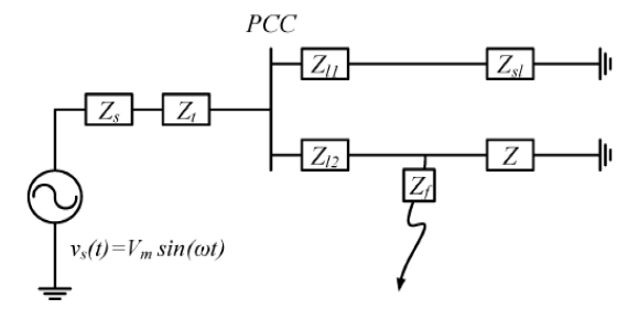
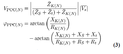
It is important to note that the main drawback of the non superconductor is a power loss which is negligible in comparison with the total power, provided by the distribution feeder. The other structures which are introduced and have two numbers of thyristor switches in the ac branch of the diode bridge. When the fault occurs, after fault detection, the thyristor switch turns off at first zero crossing and the fault current is limited to an acceptable value. These structures have switching power loss and a complicated control circuit because of thyristor switching in the normal operation. In addition, we know that thyristor operation delay (turn off at first zero crossing) causes interruptions on structure performance. So, to limit the fault current between the fault occurrence instant and thyristors turn off instant, a large reactor in the dc route is used. Due to voltage drop, harmonic distortion, and power losses, this large value of dc reactor is unfavorable. Fig. 3 shows the single-line diagram of the power system. This figure shows a substation with only two feeders F1 and F2. However, the presented analysis can be easily extended to any number of feeders, The F1 supplies a sensitive load. With a fault in the F2, the voltage sag occurs in the substation PCC. The positive-sequence equivalent circuit of such a system is shown in Fig. 4. To calculate the voltage sag, the simple voltage divider method is introduced. In the normal state, the voltage magnitude and its phase angle in the substation PCC can be expressed as follows:


III. DESIGN CONSIDERATIONS
As mentioned previously, Ldc is placed in series with the semiconductor switch to protect it against severe di/dt at the beginning of fault occurrence. So its value can be chosen, considering current characteristics of the semiconductor switch. For designing shunt branch parameters, it is possible to consider the following conditions. In the ideal case, shunt branch impedance is equal to load impedance. In this condition, when a fault occurs in the protected feeder, the voltage sag at the PCC will be zero. However, it is difficult to equate these impedances exactly because of the load variation on distribution feeders. So it is difficult to estimate the best value for Lsh and Rsh. From a practical point of view, parameters of the shunt branch can be determined by using the history of load measurements at the protected feeder. It is obvious that the feeder’s power and, consequently, its current change. For the calculation of Lsh and Rsh values, average impedance of the protected feeder is calculated. So Lsh and Rsh are chosen to be equal to its inductance and resistance. It is evident that it is possible to decrease the resistance of the shunt branch (without changing the magnitude of its impedance) in a wide range without any considerable phase-angle jump during fault. Decreasing Rsh decreases the power loss of the shunt branch during the short-circuit interval. So its design becomes simpler.
IV. RESULTS AND DISCUSSIONS
Results of this paper is as shown in bellow Figs.5 to 7.
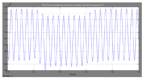
A. Three Phase Line with FCL


V. CONCLUSION
Voltage sag compensation, phase-angle jump mitigation, and fault current limiting operation due to the control method were analyzed. The proposed FCL is capable of mitigating voltage sag and phase-angle jump to acceptable levels. By using the semiconductor switch in the dc current path instead of two numbers of thyristors at the bridge branches, the proposed FCL has high speed and, consequently, the dc reactor value is reduced to a lower value. Note that the control system of this structure is simpler than previous ones. In addition, the dc voltage source placed in the proposed FCL structure reduces its THD and ac losses in normal operation. In general, this type of FCL, with the simple control circuit and low cost, is useful for the voltage-quality improvement because of voltage sag and phase-angle jump mitigating and low harmonic distortion in distribution systems. In addition to that single phase and three phase power systems are developed with and without the FCL. Their behaviors are observed.
VI. REFERENCES
[1] J. V. Milanovic and Y. Zhang, “Modeling of FACTS devices for voltage sag mitigation studies in large power systems,” IEEE Trans. Power Del., vol. 25, no. 4, pp. 3044–3052, Oct. 2010.
[2] T. J. Browne and G. T. Heydt, “Power quality as an educational opportunity,” IEEE Trans. Power Del., vol. 23, no. 2, pp. 814–815, May 2008.
[3] N. Ertugrul, A. M. Gargoom, and W. L. Soong, “Automatic classification and characterization of power quality events,” IEEE Trans. Power Del., vol. 23, no. 4, pp. 2417–2425, Oct. 2008.
[4] M. Abapour, S. H. Hosseini, and M. T. Hagh, “Power quality improvement by use of a new topology of fault current limiter,” in Proc. ECTICON, 2007, pp. 305–308.
[5] M. Brenna, R. Faranda, and E. Tironi, “A new proposal for power quality and custom power improvement: Open UPQC,” IEEE Trans. Power Del., vol. 24, no. 4, pp. 2107–2116, Oct. 2009.
[6] W. M. Fei, Y. Zhang, and Z. Lü, “Novel bridge-type FCL based on self turnoff devices for three-phase power systems,” IEEE Trans. Power Del., vol. 23, no. 4, pp. 2068–2078, Oct. 2008.
[7] E. Babaei, M. F. Kangarlu, and M. Sabahi, “Mitigation of voltage disturbances using dynamic voltage restorer based on direct converters,” IEEE Trans. Power Del., vol. 25, no. 4, pp. 2676–2683, Oct. 2010.
[8] M. Moradlou and H. R. Karshenas, “Design strategy for optimum ratingselection of interline DVR,” IEEE Trans. Power Del., vol. 26, no. 1, pp. 242–249, Jan. 2011.
[9] S. Quaia and F. Tosato, “Reducing voltage sags through fault current limitation,” IEEE Trans. Power Del., vol. 16, no. 1, pp. 12–17, Jan. 2001.
[10] L. Chen, Y. Tang, Z. Li, L. Ren, J. Shi, and S. Cheng, “Current limiting characteristics of a novel flux-coupling type superconducting fault current limiter,” IEEE Trans. Appl. Supercond., vol. 20, no. 3, pp. 1143–1146, Jun. 2010.
Source & Publisher Item Identifier: International Journal of Scientific Engineering and Technology Research
Volume.05, IssueNo.17, July-2016, Pages: 3586-3589. https://ijsetr.com/uploads/153462IJSETR10198-644.pdf
