Published by 1. Yiyin KLISTAFANI, 2. A. M. Shiddiq YUNUS, 3. Muhammad ANSHAR, 4. Sri SUWASTI, State Polytechnic of Ujung Pandang, Indonesia (1) ORCID: 1. 0000-0003-3064-9612; 2. 0000-0002-9599-6941; 3. 0000-0001-5687-5023; 4. 0000-0002-7070-9651
Abstract. Wind energy has become the most popular renewable based power plant for the last decades due to its environment benighted and large natural availability. Although modern wind turbine successfully installed worldwide, some areas with low speed wind characteristic might require a special innovation to increase the amount of conversion of extracted wind energy into electric power. One of among popular techniques for the low speed wind turbine is Diffuser Augmented Wind Turbine (DAWT) which are continued to develop from time to time for example by using numerical simulation as an early stages before manufacturing. In this paper a numerical simulations are performed to investigate the effect of attached flange on wind velocity characteristics. Numerical simulations were carried out for the flow field around various flange diffuser type structures to improve the performance of a DAWT. The present studies specifically investigate the effect of attached flange to outlet diffuser with various flange’s angle (0°, 10°, 20°, 30°) on the wind velocity characteristics. Numerical studies were conducted using the Computational Fluid Dynamics (CFD) method. The studies demonstrate that the curved diffuser with flange 10° generates the strongest increment of the wind velocity compared to the other configurations. The maximum velocity inside the diffuser increases up to 115.14%. It is found that the wind velocity at the diffuser centreline is not capable to represent the overall velocity of each section. The curved diffuser with flange 10° shows the highest increment of the average wind velocity along diffuser with the greatest increment of 102.4 % at x/L = 0.36, and the highest increment wind velocity at the diffuser centreline section at x/L = 0.18 is 115.14%.
Streszczenie. Energia wiatrowa stała się najpopularniejszą elektrownią wykorzystującą odnawialne źródła energii w ciągu ostatnich dziesięcioleci ze względu na zaciemnione środowisko i dużą naturalną dostępność. Chociaż nowoczesne turbiny wiatrowe są z powodzeniem instalowane na całym świecie, niektóre obszary o niskiej prędkości wiatru mogą wymagać specjalnej innowacji w celu zwiększenia ilości konwersji wydobytej energii wiatru na energię elektryczną. Jedną z popularnych technik dla turbin wiatrowych o niskiej prędkości jest turbina wiatrowa z dyfuzorem (DAWT), która jest od czasu do czasu rozwijana, na przykład przy użyciu symulacji numerycznej jako wczesnych etapów przed produkcją. W artykule przeprowadzono symulacje numeryczne w celu zbadania wpływu przymocowanego kołnierza na charakterystykę prędkości wiatru. Przeprowadzono symulacje numeryczne pola przepływu wokół różnych konstrukcji typu kołnierzowego dyfuzora, aby poprawić wydajność DAWT. Obecne badania w szczególności badają wpływ zamocowania kołnierza do dyfuzora wylotowego o różnym kącie kołnierza (0°, 10°, 20°, 30°) na charakterystykę prędkości wiatru. Badania numeryczne przeprowadzono metodą obliczeniowej dynamiki płynów (CFD). Z przeprowadzonych badań wynika, że zakrzywiony dyfuzor z kołnierzem 10° generuje najsilniejszy przyrost prędkości wiatru w porównaniu z innymi konfiguracjami. Maksymalna prędkość wewnątrz dyfuzora wzrasta do 115,14%. Stwierdzono, że prędkość wiatru w osi dyfuzora nie jest w stanie przedstawić całkowitej prędkości każdej sekcji. Zakrzywiony dyfuzor z kołnierzem 10° wykazuje największy przyrost średniej prędkości wiatru wzdłuż dyfuzora z największym przyrostem 102,4% przy x/L = 0,36, a największy przyrost prędkości wiatru w środkowej części nawiewnika przy x/L = 0,18 to 115,14%. (Ocena konstrukcji dyfuzorów kołnierzowych w celu poprawy wytwarzania energii w turbinie wiatrowej ze wspomaganiem dyfuzorem)
Keywords: CFD, DAWT, Diffuser, Flange, Wind energy, Wind turbine
Słowa kluczowe: turbina wiatrowa, dyfuzor, .
Introduction
The potential for renewable energy in the world is quite large and has the potential to be developed. One of the potential renewable energy that can contribute significantly to energy needs is wind energy. Wind energy is one of the very clean and sustainable energy sources that abundantly available naturally. Currently, wind energy covers about 6% of the global electricity demand (https://wwindea.org/worldwind-capacity-at-650-gw/). The potential of wind energy is huge and study shows if 20% of the possible wind resources are able to be utilized [1]. One of the problems in the utilization of wind energy conversion technology is that the wind speed is too low for the application. It is well known that wind turbines usually operate for the rated wind speed of around 8-11 m/s [2], [3]. The power of the wind is proportional to the cubic power of the wind velocity approaching a wind turbine. This means that even a small amount of its acceleration gives large increase on the energy generation [4]. Therefore, wind turbine innovation is very important to optimizing the utilization of wind energy, especially in areas with low wind speed characteristic. One of the developments in wind turbine innovation is the DAWT (Diffuser Augmented Wind Turbine) concept which is equipped with a diffuser sheath on the rotor. The use of diffuser is intended to increase the effective wind speed, therefore, the power produced by wind turbines increases.
There are many studies that focus on wind turbine innovations in increasing wind speed, for example the studies from Refs [5]-[8]. Studies that focusing on finding ways to increase the wind speed are introduced by Kannan et al [5], Lipian et al [6], [7], and Khamlaj and Rumpfkeil 8. Yadav and Kumar [9] have also reviewed related shrouded wind turbines with low wind speeds. In the previous study, Ohya et al. [10] developed the diffuser structures by attached flange at the exit periphery to the diffuser body. It was confirmed in the study that the diffuser structure with flange was effective for collecting and accelerating the wind than diffuser without flange. In addition, the power output coefficient increase five times greater than conventional wind turbines. The development study related of DAWT has also been carried out in the previous study by Yiyin et al [11] where in the study the diffuser type structures are modified into four types, namely flat diffuser, curved diffuser, flat diffuser with inlet shroud, and curved diffuser with inlet shroud. The results obtained from the study that the curved diffuser showed the highest improvement of the centreline and average wind velocities along diffuser. The greatest observed increment was 76.99 % at with the maximum average wind velocity of 8.85 m/s.
With the development of computer technology and engineering software evolution, it is possible to model engineering problems using Computational Fluid Dynamics (CFD) approaches for example the CFD simulation for Darrieus Type Wind Turbine for performance investigation [12], [13]. The simulations range from the simplest 2D Reynolds-Averaged Navier-Stokes (RANS) approach to the most complex Direct Numerical Simulation (DNS) approach. A good agreement of the CFD computations using the SST turbulence model was obtained in several computations, for example Pape and Lecanu [14], Sørensen et al [15], Bangga et al [16] and [17], Weihing et al, [18], and Jost et al [19]. These encourage the use of CFD for predicting the fluids engineering problems especially with the help of the Menter SST k-ω model. Having considered the above background, the development of a wind power system with high output aims at determining how to collect wind velocity efficiently and what kind of diffuser design can generate energy effectively from the wind speed. In the present studies, several numerical investigations will be carried out for the flow field around diffuser structures aiming to identify the optimized configuration.
Numerical Methods
The CFD studies mainly concern about the flow development around four types of diffuser with attached flange at the exit diffuser.
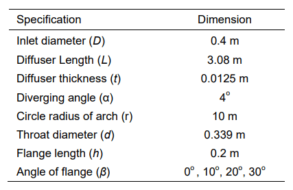
A steady two-dimensional approach was employed for the present studies. It will be shown that this is sufficient for predicting the main flow features, but not the wake behavior of the flow. However, the latter is not of interest as the focus of the present studies is only for estimating the flow acceleration inside the diffuser. The geometry was created using the Ansys workbench 2019 R1. The curved diffuser was generated according to the geometry specified in the numerical studies carried out by Klistafani et al [11], where the curved diffuser is a geometry that can provide the best performance improvement for DAWT compared to a flat diffuser. The diffuser has a thickness of 1.25 cm. This was designed based on the recent studies by Hu and Wang (2015) who employed ten layers of plate with each has a thickness of 1.25 mm. The flange length (h) used is 0.2 m referring to previous studies [5], [8]. Four different types of the diffuser were introduced, namely curved diffuser with flange 0°, 10°, 20°, and 30°. These structures are illustrated in Figure 1. Detailed information about their dimension is given in Table 1 and Figure 2.

Table 1. Diffuser type structure (2D) dimensions
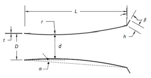
The domain of the simulation is illustrated in Figure 3. The inlet of the flow is located at 5 times the inlet diameter of the diffuser (D). The velocity inlet boundary condition was applied at this location. The flow leaves the computational domain at 8.5D distance from the outlet plane of the diffuser with the outflow boundary condition. The side walls were set as a non-slip wall that are sufficiently far away from the area of interest to ensure the minimal effect on the flow characteristics near the diffuser. The computations were carried out using the commercial software Ansys Fluent 2019 R1. The flow was assumed to be steady and the incompressibility effect was neglected. This is reasonable because wind turbines usually operate at a much smaller velocity than the speed of sound. An initial undisturbed wind velocity of 5 m/s was prescribed at the velocity inlet plane. The same velocity was employed by Ohya et al [10] in their experiment. The turbulence closure was modelled using the two-equation SST k-ω model according to Menter [20]. This model combines the the standard k-ε model [21] in the freestream and the Wilcox k-ω model [22] for the wall bounded flow. The model is good for predicting flows with a strong adverse pressure gradient as demonstrated already in [11], [15]-[19], [23]-[25]. The pressure velocity coupling uses the SIMPLE method. All the variables were solved using the second order discretization. The computations were carried out for 10,000 iterations, otherwise convergence was achieved if the residual of the momentum reaches 1e-6.
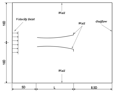
The mesh was generated using ANSYS Workbench 2019 R1 software. Mesh parameters and controls are shown in Table 2. An enlarged view of the mesh near the curved diffuser wall is shown in figure 4. Grid independence studies were carried out in advance to ensure that the results are independent of the mesh resolution. The results are shown in table 3 where the streamwise velocity ratios (U/U∞) of the five meshes are compared. It can be seen that Grid 3 has an optimal grid size with a number of cells is 50,310. Adding the number of cells as in Grid 4, it doesn’t give too much computational results, with a prediction difference value of 3.7%.
Table 2. Mesh parameters and controls
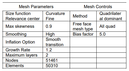
Table 3. Grid Independence – Difference value of streamwise flow
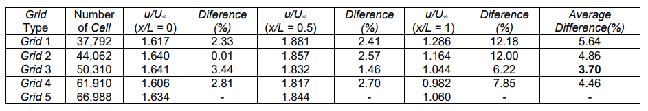
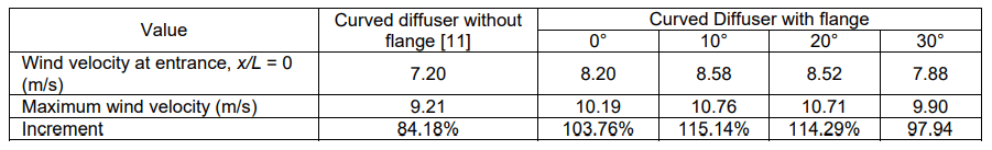
Table 4. Wind velocity at midline for all curved diffuser type structures compare with curved diffuser without flange [11]
Results and Discussion
The dimensionless streamwise velocity U/U∞ at midline diffuser plots for five diffuser type structures are presented in figure 5. In case of the diffuser type structures, the distribution of the axial velocity reveals that the maximum velocity occurs for curved diffuser with flange 10°. All of the diffuser structures by attached flange at the exit periphery to the diffuser body give a positive impact on increasing wind speed. The difference in increased velocity generated by the curved diffuser flange 10° compared to diffuser without flange [11] is 30.96%. The curved diffuser with flange 10° shows a better performance, although curved diffuser with flange 20° also give great increment of wind speed. The difference of its increment is very small (0.85%). Maximum wind speed of curved diffuser with flange 10° is not occurs at entrance position, but at x/L = 0.18. Detailed information regarding the comparison of the wind velocity at midline of all diffuser type structures is shown in table 4.
Further comparison of the dimensionless streamwise velocity U/U∞ for four diffuser type structures and curve diffuser without flange [11] are presented in figure 6, in which the average velocity data are taken at each section of diffuser. As shown in figure 6, diffusers equipped with the flange have the bigger average wind velocity through inside diffuser than curved diffuser without flange. At the inlet diffuser section (x/L = 0), the highest value of the averaged wind speed occur in curved diffuser with flange 10° and 20°. However the curved diffuser with flange 10° has the highest maximum average wind speed than others in the inside diffuser (x/L = 0.36). The difference increment value of maximum averaged wind speed generated by curved diffuser 10° compare with curved diffuser without flange is 25.47%. the highest maximum average wind speed is 10.12 m/s with the increment value is 102.45%.
Comparison of velocity contour on curved diffuser without flanges and with flanges 10° can be seen in Figure 7. Vortices flow at downstream diffuser with flanges 10° larger (indicated by blue area) than flow through curved diffuser without flange. The large vortexes in the downstream area have suction effect in the upstream areas; as a result the wind that crosses the upstream diffuser increases the wind velocity (indicated by orange contour). The velocity contour strengthen the previous discussion (Figures 5 and 6), namely curved diffuser with a flange 10° giving better performance than curved diffuser without flange. As informed in table 4, the difference wind increment of both geometries is 30.96%.
In line with the discussion result of the velocity contour, the pressure contour also shows that the curved diffuser with flange10° provides the best performance. This is indicated by the high pressure in the downstream region and at area around the diffuser wall, thereby strengthening the evidence that the suction effect caused by the curved diffuser with the flange 10° is very strong compared to the diffuser without the flange. Pressure contour regarding the comparison of curved diffuser without and with flange 10° is shown in figure 8.
In line with the discussion result of the velocity contour, the pressure contour also shows that the curved diffuser with flange 10° provides the best performance. This is indicated by the high pressure in the downstream region and at area around the diffuser wall, thereby strengthening the evidence that the suction effect caused by the curved diffuser with the flange 10° is very strong compared to the diffuser without the flange. Pressure contour regarding the comparison of curved diffuser without and with flange 10° is shown in figure 8.

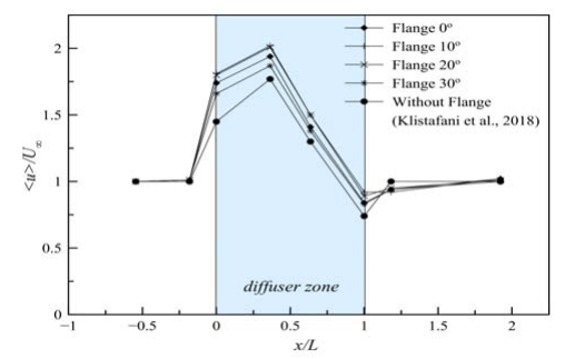
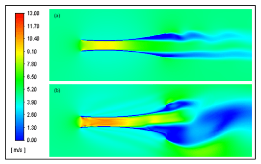
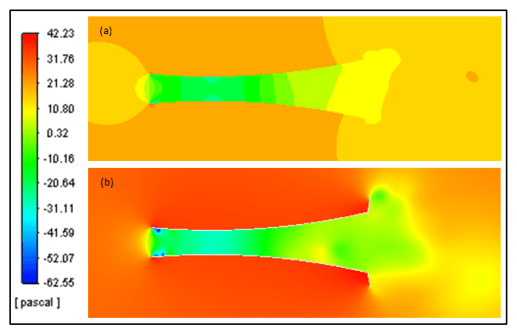
Figure 9 presents the velocity profiles for different flange angle of diffuser compared with curved diffuser without flange and without diffuser at all. It’s to clarify the rate of wind flow within various configuration of diffuser. It can be seen that the wind velocity at the upstream zone is same for all the configurations of curved diffuser. The wind velocity at section x/L = -0.54 (far away from inlet diffuser) not influenced by the presence of the curved diffuser. It becomes evident that the wind velocity slightly increases at the near inlet diffuser (x/L = -0.18), although the difference of wind velocity increases for all the curved diffuser within and without diffuser is small. The increase in wind velocity is clearly visible when entering the diffuser (x/L = 0), where the curved diffuser equipped with the flange 10° and 20° have the good performance than the others. However, the greatest increase in wind velocity along the diffuser (x/L = 0.36 until x/L = 1) is actually generated by the curved diffuser with flange 10°. Overall, it can be clearly seen that Curved diffuser equipped with flange have wind velocity increment bigger than curved diffuser without flange (x/L = – 0.18 until x/L = 1).
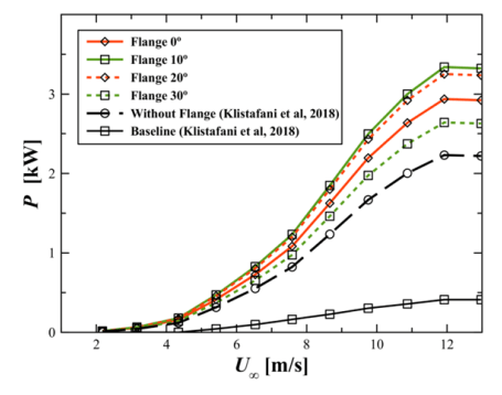
The research vertical axis wind turbine (VAWT) investigated by Saedi et al [26] is considered to estimate the generated power production of the turbine equipped with the curved diffuser with flange. The turbine has a radius of 2 m and a height of 1.38 m. The estimated power curves of the turbine for various wind speeds and curved diffusers with flange can be seen on figure 10. In these plots the turbine is assumed to be located at x/L = 0.36 where the maximum average wind speed takes place. Flange that equipped at outlet diffuser can improve generated power of turbine significantly than diffuser without flange. Curved diffuser with flange 10° has the greatest estimated generated power production than others.
A diffuser with a flange angle 0° has 12% lower power (2.9369 kW) than the power generated by a flange diffuser 10° (3.3395 kW). However, the addition of the flange angle is not in line with the increase in power generated, when the flange angle is enlarged to 20°, the resulting power decreases by 2.6% to 3.2519 kW. A diffuser with a flange angle 30° produces less power than a diffuser with another flange, which is 2.6421 kW. The research vertical axis wind turbine (VAWT) investigated by Saedi et al [26] is considered to estimate the generated power production of the turbine equipped with the curved diffuser with flange. The turbine has a radius of 2 m and a height of 1.38 m. The estimated power curves of the turbine for various wind speeds and curved diffusers with flange can be seen on figure 10. In these plots the turbine is assumed to be located at x/L = 0.36 where the maximum average wind speed takes place. Flange that equipped at outlet diffuser can improve generated power of turbine significantly than diffuser without flange. Curved diffuser with flange 10° has the greatest estimated generated power production than others. A diffuser with a flange angle 0° has 12% lower power (2.9369 kW) than the power generated by a flange diffuser 10° (3.3395 kW). However, the addition of the flange angle is not in line with the increase in power generated, when the flange angle is enlarged to 20°, the resulting power decreases by 2.6% to 3.2519 kW. A diffuser with a flange angle 30° produces less power than a diffuser with another flange, which is 2.6421 kW.

Conclusion
Numerical simulations have been carried out for flow fields around curved diffuser with various angle of flange. The main conclusions derived from the study are as follows:
1. All of the diffuser structures by attached flange at the exit periphery to the curved diffuser body give a positive impact on increasing wind velocity.
2. Curved diffuser flange 10° shows the highest improvement of wind velocities, not only the centreline wind velocity but also the average wind velocity. The highest increment of the wind velocity at the diffuser centerline section is 115.14% with the maximal velocity is 10.76 m/s.
3. The curved diffuser with flange 10° has the greatest maximum average wind speed than others in the inside diffuser (x/L = 0.36). the highest maximum average wind speed is 10.12 m/s with the increment value is 102.45%.
4. Curved diffuser with flange 10° has the greatest estimated generated power production around 3.3395 kW.
5. The curved diffuser with flange 10° very suitable to be used as a wind turbine shroud to improved wind turbine performance.
Acknowledgements – The authors would like to acknowledge the funding support of directorate of research and community service, directorate general of strengthening research and development, ministry of research, technology and higher education of Indonesia.
REFERENCES
[1] Qasim, A.Y., Usubamatov, R., Zain, Z.M. and Quad, G.A., 2012. The parameters affect on power coefficient vertical axis wind turbine. IIUM Engineering Journal, 13(1).
[2] Bangga, G., Hutomo, G., Wiranegara, R. and Sasongko, H., 2017. Numerical study on a single bladed vertical axis wind turbine under dynamic stall. Journal of Mechanical Science and Technology, 31(1), pp.261-267.
[3] Bangga, G., Kusumadewi, T., Hutomo, G., Sabila, A., Syawitri, T., Setiadi, H., Faisal, M., Wiranegara, R., Hendranata, Y., Lastomo, D. and Putra, L., 2018, January. Improving a twoequation eddy-viscosity turbulence model to predict the aerodynamic performance of thick wind turbine airfoils. In J. Phys.: Conf. Ser (Vol. 974, No. 1, p. 12019).
[4] Abe, K.I. and Ohya, Y., 2004. An investigation of flow fields around flanged diffusers using CFD. Journal of wind engineering and industrial aerodynamics, 92(3-4), pp.315-330.
[5] Kannan, T.S., Mutasher, S.A. and Lau, Y.K., 2013. Design and flow velocity simulation of diffuser augmented wind turbine using CFD. journal of engineering science and technology, 8(4), pp.372-384.
[6] Lipian, M., Karczewski, M. and Olasek, K., 2015. Sensitivity study of diffuser angle and brim height parameters for the design of 3 kW Diffuser Augmented Wind Turbine. Open Engineering, 1(open-issue).
[7] Lipian, M., Karczewski, M., Molinski, J. and Jozwik, K., 2016. Numerical simulation methodologies for design and development of Diffuser-Augmented Wind Turbines–analysis and comparison. Open Engineering, 1(open-issue).
[8] Khamlaj, T.A. and Rumpfkeil, M.P., 2018. Analysis and optimization of ducted wind turbines. Energy, 162, pp.1234-1252.
[9] Yadav, A.K. and Kumar, D., 2017. Review of a Shrouded Wind Turbine for Low Wind Speeds. International Digital Library of Technology & Research, Vol. 1, Issue 5.
[10] Ohya, Y., Karasudani, T., Sakurai, A., Abe, K.I. and Inoue, M., 2008. Development of a shrouded wind turbine with a flanged diffuser. Journal of wind engineering and industrial aerodynamics, 96(5), pp.524-539.
[11] Klistafani, Y., Mukhsen, M.I. and Bangga, G., 2018. Assessment of various diffuser structures to improve the power production of a wind turbine rotor. Technische Mechanik. Scientific Journal for Fundamentals and Applications of Engineering Mechanics, 38(3), pp.256-266.
[12] Damian Mazur., Analiza CFD pionowej turbiny wiatrowej typu Darrieus, Journal Przeglad Elektrotecnichzny, 08/2013 Page no. 77. 2013
[13] Damian Mazur., Static analysis of the Darrieus wind turbine including loads from the numerical fluid mechanics, Journal Przeglad Elektrotecnichzny, 10/2013 Page no. 293.2013.
[14] Pape, A.L. and Lecanu, J., 2004. 3D Navier–Stokes computations of a stall-regulated wind turbine. Wind Energy: An International Journal for Progress and Applications in Wind Power Conversion Technology, 7(4), pp.309-324.
[15] Sørensen, N.N., Michelsen, J.A. and Schreck, S., 2002. Navier–Stokes predictions of the NREL phase VI rotor in the NASA Ames 80 ft× 120 ft wind tunnel. Wind Energy: An International Journal for Progress and Applications in Wind Power Conversion Technology, 5(2-3), pp.151-169.
[16] Bangga, G., Lutz, T. and Krämer, E., 2017. Root flow characteristics and 3D effects of an isolated wind turbine rotor. Journal of Mechanical Science and Technology, 31(8), pp.3839-3844.
[17] Bangga, G., Lutz, T., Jost, E. and Krämer, E., 2017. CFD studies on rotational augmentation at the inboard sections of a 10 MW wind turbine rotor. Journal of Renewable and Sustainable Energy, 9(2), p.023304.
[18] Weihing, P., Letzgus, J., Bangga, G., Lutz, T. and Krämer, E., 2016, September. Hybrid RANS/LES capabilities of the flow solver FLOWer—Application to flow around wind turbines. In Symposium on hybrid RANS-LES methods (pp. 369-380). Springer, Cham.
[19] Jost, E., Fischer, A., Bangga, G., Lutz, T. and Krämer, E., 2017. An investigation of unsteady 3-D effects on trailing edge flaps. Wind Energy Science, 2(1), p.241.
[20] Menter, F.R., 1994. Two-equation eddy-viscosity turbulence models for engineering applications. AIAA journal, 32(8), pp.1598-1605.
[21] Launder, B.E. and Spalding, D.B., 1972. Mathematical models of turbulence (No. BOOK). Academic press.
[22] Wilcox, D.C., 1993. Turbulence Modelling for CFD, DCW Industries Inc., La Canada, California. IBSN 0-9636051-0-0.
[23] Hu, J.F. and Wang, W.X., 2015. Upgrading a shrouded wind turbine with a self-adaptive flanged diffuser. Energies, 8(6), pp.5319-5337.
[24] Bangga, G. and Sasongko, H., 2017. Dynamic stall prediction of a pitching airfoil using an adjusted two-equation URANS turbulence model. Journal of Applied Fluid Mechanics, 10(1), pp.1-10.
[25] Bangga, G., Weihing, P., Lutz, T. and Krämer, E., 2017. Effect of computational grid on accurate prediction of a wind turbine rotor using delayed detached-eddy simulations. Journal of Mechanical Science and Technology, 31(5), pp.2359-2364.
[26] Saeidi, D., Sedaghat, A., Alamdari, P. and Alemrajabi, A.A., 2013. Aerodynamic design and economical evaluation of site specific small vertical axis wind turbines. Applied energy, 101, pp.765-775.
Authors: Yiyin Klistafani, ST,MT, Energy Conversion Study Program, Mechanical Engineering, State Polytechnic of Ujung Pandang, Indonesia, E-mail: yiyin_klistafani@poliupg.ac.id; A. M. Shiddiq Yunus, ST, MEngSc, PhD, Energy Conversion Study Program, Mechanical Engineering, State Polytechnic of Ujung Pandang, Indonesia, E-mail:shiddiq@poliupg.ac.id;Prof. Ir. Muhammad Anshar, M.Si, PhD, Power Engineering Study Program, Mechanical Engineering, State Polytechnic of Ujung Pandang, Indonesia, E-mail: muh_anshar@poliupg.ac.id; Sri Suwasti, ST,MT, Energy Conversion Study Program, Mechanical Engineering, State Polytechnic of Ujung Pandang, Indonesia, Email: sri_suwasti@poliupg.ac.id;
Source & Publisher Item Identifier: PRZEGLĄD ELEKTROTECHNICZNY, ISSN 0033-2097, R. 98 NR 4/2022. doi:10.15199/48.2022.04.05
