Published by Saktanong WONGCHAROEN1, Sansak DEEON1, Narong MUNGKUNG2, Pathumwan Institute of Technology, Thailand (1), King Mongkut’s University of Technology Thonburi, Thailand (2)
Abstract. This research presented an electronic load circuit for electrical safety by using a serial mode comparator as a protection device against surges caused by electrical power lacking stability and quality. The application of comparators in detecting overvoltage and driving electronic load is possible because of a transistor which is a simple device for failure prevention used in the circuit design. The properties of the circuit can be set. Relation management for failures which might occur in the electrical system is done through SPDs for surge protection. The electronic load is used as a device to reduce swell. The experiment showed that the electronic load circuit could work according to the design, without any failure, and was efficient. The let-through voltage which came to the load did not reach the level at which electrical devices and electronics would get the failure. The circuit could work without interruption. Moreover, the results from the Failure Modes and Effects Analysis (FMEA) showed that they met the specified standards.
Streszczenie. W pracy przedstawiono układ obciążenia obwodu elektrycznego/elektronicznego zabezpieczający obwód przed uszkodzeniem powodowanym przez brak stabilności zasilania. Układ wykorzystuje szeregowo połączenie komparatorów reagujących na przepięcia. Eksperymenty wykazały skuteczne działanie obwodu. Zastosowanie obwodu z szeregowo połączonymi komparatorami do zabezpieczania układów elektrycznych przed przepięciami.
Keywords: Electronic load, Comparators, Swell voltage, Failure modes and effects analysis (FMEA).
Słowa kluczowe: przepięcia, zabezpieczenia, komparatory.
Introduction
Development of a country requires modern technology to drive the growth of the nation in terms of economic value. The electricity and electronics industries have played a significant role in enabling such progress and creating innovations for other industries. There are many important parts of many products such as electrical devices, electrical power devices, automotive electronics, medical tools, smart agriculture, sensors, communication devices, and energy management systems. As the age of Industry 4.0 approaches, electrical devices have been used by people with greater frequency for their convenience. With artificial intelligence from electronics technology, many electrical devices have become smarter. Further, technology has also advanced, resulting in quicker speeds for their response. Changes in the electrical systems which supply technologies might lead to the problem of electricity quality in the future. A question might arise from the voltage, current and frequency rate from the normal state, as specified in IEEE Std. 1159 [1], which might be natural phenomena, electrical failure, device switching, incorrect grounding, or others [2], as shown in Fig. 1
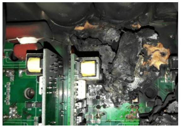
These problems will not only cause failure in the electrical system and electrical devices in terms of quality, but also put users in danger. There are two types of issues regarding surge: 1) Overvoltage for a short period, which is caused by lightning. There are many prevention devices according to IEEE Std. C62.41, such as GDT and MOV. Although there are many protection devices, some electrical and electronic devices still experience failure, as shown in Fig. 1. This problem with swell has not been solved successfully in all cases 2) Failures in the electrical system in each region of Thailand are different. As such, they need to be analysed to improve the quality of electrical power based on actual events.
This paper presents a way to reduce the failures that occur in electrical and electronic devices which are connected to the electrical system and caused by the swell. The electronic load is used as a device to reduce such failure, while a comparator circuit is used to detect the level of swell for comparison with the reference level of swell. The comparator circuit contains a transistor [3-6]. To make a comparison, the window is designed to detect different levels of voltage [7]. It is connected in a serial mode [8,9] so that it can work for safety.
Relationships of Surge Protection Device
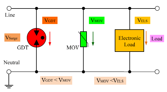
To manage the relationships of surge protection device (SPD) [10,11], it is essential to consider the relationships in terms of reception, limitation or absorption of energy in each device. That is, GDT at the first end must be able to suppress the power (VGDT) caused by lightning to transfer to a MOV device next to the VMOV to decrease the level so there is no failure in accordance with the IEEE Std C62.41 [12,13]. If the overvoltage cannot be suppressed or it decreases below the working condition, a swell protection device with electronic load can still reduce it so that the voltage VELS is at a safe level for electrical and electronic devices. The devices also work smoothly. The relationship management for the surge protection device can be shown in Fig. 2.
The majority of electrical devices are designed to work with 230 VAC. If there is a failure in the electrical system, in this case, overvoltage (230VAC±10%) [14], the electrical device might malfunction or experience failure to the point that repair is not possible [15].
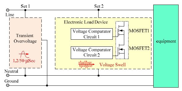
Fig. 3 shows the block diagram of the surge protection device for AC. Inside the surge protection device, there are two kinds of operation. First, the surge protection device consists of GDT and MOV devices with the fastest response time to control the let-through voltage so that it is manageable. Second, a swell suppressor consists of electronic load to control the clamping voltage to remain in the standard range.
Swell voltage comparator detector
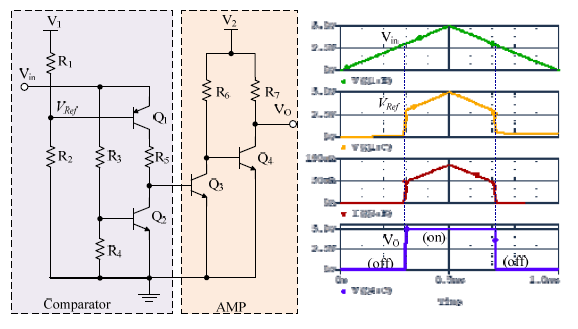
A comparator has been designed with transistors to compare the voltages, as shown in Fig. 4.

A comparator circuit without feedback consists of 2 transistors [5-7]. Transistor Q1 provides the comparator with the function of amplification for input signal, as shown in Equations (1) and (2).
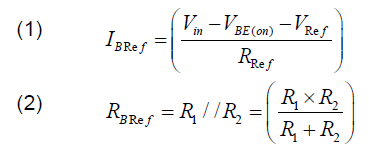
VO is set so that the reference voltage can be used as VRef. The reference voltage is calculated from resistance R1 and R2 in the format of voltage divider circuit, as shown in Equation (3) with the clamping voltage at VBE of Q1, as shown in Equation (4).
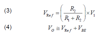
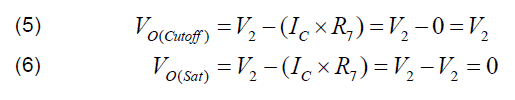
To use a comparator with no feedback, a circuit can be added to increase the output signal so that the output signal can be logically set as 0 (off) or 1 (on). Transistors Q4 will work as a switch to provide bias to the transistors to stay in a cut-off mode and the same status as an open circuit. The bias will then be supplied to the transistors to be in a saturation mode, the same status as a closed circuit, as shown in Equation (5). A large amount of current will pass through the transistors, and the output voltage will have the same value as 0, as shown in Equation (6).
When the voltage Vin is less than the reference voltage VRef, the output signal of the comparator will be 0V. When the voltage Vin is higher than the reference voltage VRef, the output voltage of the comparator will be similar to V2, as shown in Fig. 5
Block diagram of a comparator
The comparator circuit with increased output signal circuit can be illustrated as a block diagram similar to opamp, as shown in Fig. 6.
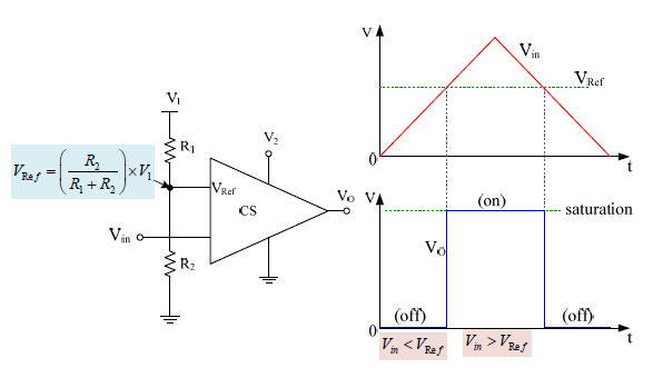
To design comparators, there is only one reference voltage. The output voltage is set to calculate resistance values R1 and R2 as voltage divider circuit. When Vin < VRef, the the output voltage will be the same as the voltage put to V2. When Vin > VRef, the output voltage will be 0.
Two-level comparator circuit
In the two-level comparator circuit for electronic load in a serial mode, there must be comparator CS1 and CS2 to detect the voltage level. When the input voltage Vin is the same as the reference voltage VRef1, there will be output signal VO1 to make MOSFET1 turn ON [16]. When the voltage Vin is higher and becomes the same as the reference voltage VRef2 , the output signal VO2 of CS2 will make MOSFET2 turn ON, resulting in the current IO passing through both MOSFETs in a serial mode. When the input voltage Vin decreases and becomes the same as the reference voltage VRef2, the output of the comparator CS2 will be 0, making MOSFET2 turn OFF. When the voltage Vin decreases and becomes the same as the reference voltage VRef1, the output of the comparator CS1 will be 0, making MOSFET1 turn OFF. When there is no electricity IO, the electronic load stops working, as shown in Fig. 7. T1 and T2 are shown in Equation (7).

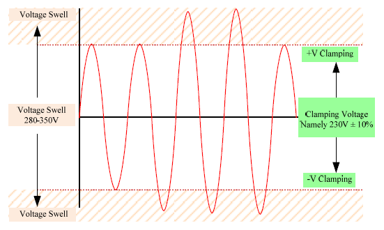
The principle of the surge protection device The electronic load circuit to reduce swell voltage in the low voltage electrical system has been designed with the voltage RMS, which is higher than the standard level (namely 230V±10%). The circuit has been designed in parallel without considering the electrical load current. When there is overvoltage in the system, comparators CS1 and CS2 will detect the voltage level to drive the electronic load in a serial mode [9], as shown in Fig. 8.
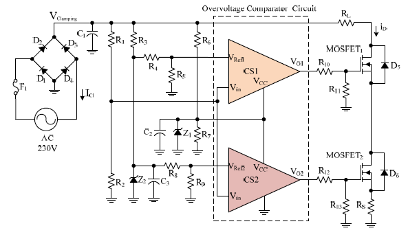
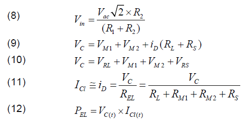
When voltage Vin reaches the specified level, as shown in Equation (5), there will be output signals VO1 and VO2 in order to drive the electronic load by overvoltage in the system. The electronic load circuit will take the current (Leakage Current :ICl) and control the clamping voltage (Clamping Voltage : VClamping or VC) to be in a suitable range, as shown in Equations (6) and (7). MOSFET will act as a receptor of overvoltage as another load in the system, as shown in Equations (8)-(12) [15-16].
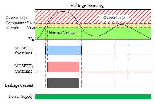
According to Fig. 9, the electronic load circuit alongside a comparator to detect swell has been set regarding the reference voltage for VRef1 and VRef2. When there is overvoltage, comparator CS1 will make MOSFET1 turn ON. When there is overvoltage remaining, comparator WCS2 will turn ON, resulting in leakage current passing through MOSFET2 for the entire circuit. Overvoltage will be reduced in the form of electrical waves, as shown in Fig. 10.
The electronic load circuit has been designed for safety by using comparators in a serial mode. The failure and possible effects have been analysed with the comparator circuit in accordance with the safety principles to ensure that the electronic load circuit with comparators works reliably without any critical failures. There were two sets of devices for testing: a surge protection device and a swell suppressor.
Safety analysis of comparator
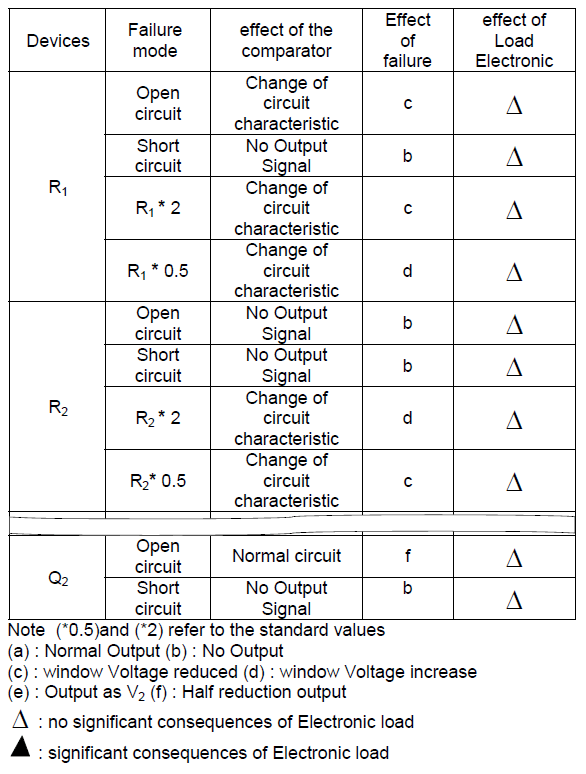
To analyse the type of failure and possible effects, the method called Failure Modes and Effects Analysis (or FMEA) [17] has been used to identify the failure in safety of the electronic load circuit in order to prevent collapse. The analytical principle has been set in IEC 61496-1 [18]. The results of the analysis can confirm that when there is a failure in the electronic load, the system will show Fail-Safe status [19]. Further, the system must not cause any failure, as shown in Table 1.
Table 1. FMEA of the developed comparator
Test results of the surge protection device
The circuit has been set up to test SPDS GDT and MOV. Test waves have been added in accordance with the standards IEEE [12,13] and IEC 20 at 6,000V and the oscilloscope has been used to measure the letthrough voltage (Vlt) at the output. The results were recorded in Table 2.
Table 2. Test results for the surge protection device
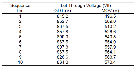
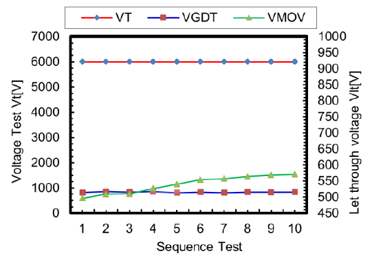
According to Fig. 11, there is a relationship between the voltage test at 6,000V and let-through voltage through surge protection devices GDT and MOV. The output signal waves for the surge protection devices GDT and MOV are shown in Figs. 12 and 13.
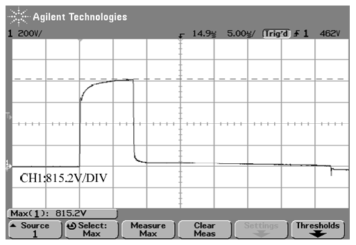
Test results from the swell suppressor
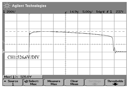
To test the swell suppressor, the electronic load has been added to suppress the swell, as shown in Fig. 14. The swell waves are shown in Fig. 15.
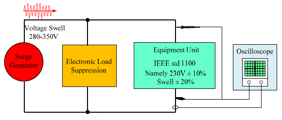
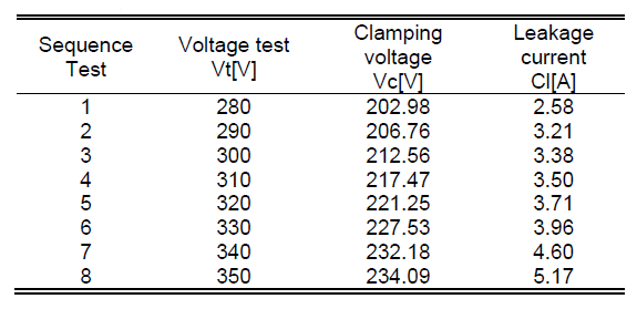
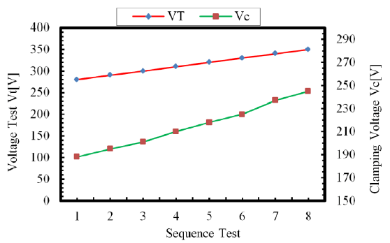
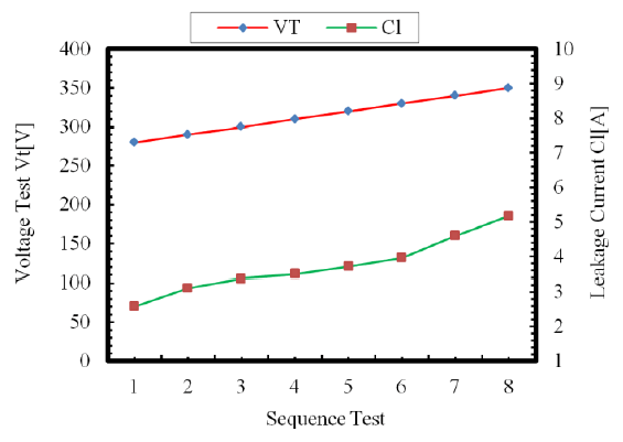
After the setup, AC voltage was added with 280V-350V at 50 Hz. The overvoltage test waves are shown in Fig. 16, and the oscilloscope has been used to measure the electrical current and clamping voltage at the output. The data was recorded in Table 3.
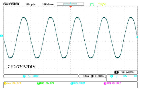
Table 3. Test results for the electronic load in the swell suppressor
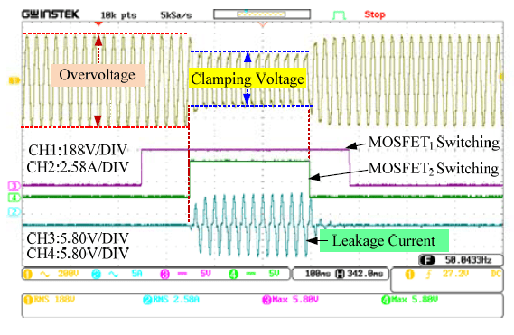
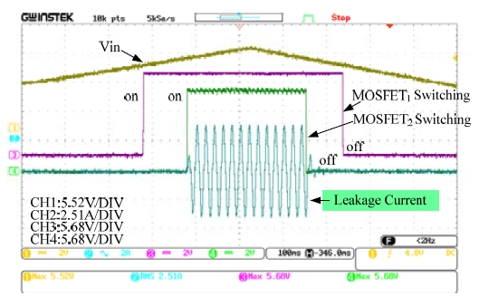
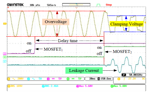
According to Fig. 19, the signal waves of the electronic load and the let-through voltage at the output of the electronic load are shown. CH1 is the swell waves. When there is an output signal, the comparator works at CH3. CH4 is the wave for electronic load in the let-through voltage at CH2. When the signal waves are magnified, there is delay time to detect any failure caused by the overvoltage, resulting in the safety of the electronic load, as shown in Fig. 20.
Conclusion
This research paper presents an electronic load circuit for safety by using comparators in a serial mode as a surge protection device for a low-voltage electrical system. When the quality of the electrical system is inadequate, it might cause failures in electrical and electrical appliances. The design has been organised to consider the potential failures to electrical and electronic devices by managing the relationships between surge protection devices (SPDs) to suppress overvoltage in the magnetic field caused by lightning. To design the electronic load circuit, comparators were used to detect overvoltage. Transistors were used in the design of the comparators and devices were used by the principle alongside the analysis from the computer software as well as the actual devices. The results in the previous section show that they accord to the design. The developed electronic load can accurately work out a failsafe status. The test results from the Failure Modes and Effects Analysis (FMEA) were according to the standards IEC 61496-1. In this paper, there were 2 types of surge protection devices assessed, with the results as follows: 1) Test results from the surge protection devices were in accordance with the designed experiment and as expected. The surge protection devices could suppress overvoltage from the magnetic field caused by lightning when signal waves complying with the IEEE C62.41 at 6,000V (1.2/50µS) were used. The let-through voltage was low and acceptable. 2) Test results from the swell suppressor followed the designed experiment and were as expected. The electronic load could suppress overvoltage when it was over the standards, resulting in the clamping voltage to remain at an acceptable level.
REFERENCES
[1] IEEE Std 1159-2009, IEEE Recommended Practice for Monitoring Electric Power Quality, 2009.
[2] J. Kaniewski, “Transformator hybrydowy z dwubiegunowym przekształtnikiem AC/AC bez magazynu energii DC,” Przegląd Elektrotechniczny, ISSN 0033-2097, 94 (2018), nr 5, 80-85.
[3] C.-S. Plesa, B. Dimitriu, M. Neag, “Design Options for Current Limit and Power Limit Circuit Protections for LDOs,” Advances in Electrical and Computer Engineering Vol.19, no.1, pp.57-62, 2019.
[4] E. J. Wade and D. S. Davidson, “Application of Transistors to Safety Circuits,” IRE Transactions on Nuclear Science, vol. 5, issue 2, pp. 44–46, Aug. 1958.
[5] K. Futsuhara, and M. Mukaidono, “A Realization of Fail-safe Sensor Using Electromagnetic Induction,” IEEE Conference on Precision Electromagnetic Measurements CPEM, Ibaraki, Japan, pp. 99-100,1988.
[6] K. Futsuhara, and M. Mukaidono, “Application of Window Comparator to Majority Operation,” IEEE 19th International Symposium on Multiple-Valued Logic, Guangzhou, China, pp. 114-121, 1989.
[7] M. Sakai, M. Kato, K Futsuhara, and M. Mukaidono, “Application of Fail-safe Multiple-valued Logic to Control of Power Press,” IEEE 22nd International Symposium on Multiple-Valued Logic, Sendai, Japan, pp. 271-350, 1992.
[8] C. Summatta, S. Deeon, “Simple Anti Capacitor Open-circuit Self-oscillation in a CMOS Schmitt trigger-invertor Oscillator circuit for a Fail-safe Relay Drive,” PRZEGLĄD ELEKTROTECHNICZNY, Vol.3, no. 23, pp.97-100, 2019.
[9] C. Summatta, W. Khamsen, A. Pilikeaw, S. Deeon, “Design and Simulation of Relay Drive Circuit for Safe Operation Order,” Proceedings of the 2nd International Conference on Mathematics, Engineering and Industrial Applications 2016 (ICoMEIA 2016), pp.. 030031-1–030031-8, 2016.
[10] P. Hasse, “Overvoltage Protection of Low Voltage Systems,” 2nd Edition, IEE Power and Energy Series 33, The Institution of Electrical Engineers, London, pp. 127-204, 2000.
[11] V. Radulovic, S. Mujovic, Z. Miljanic, “Characteristics of Overvoltage Protection with Cascade Application of Surge Protective Devices in Low-Voltage AC Power Circuits,” Advances in Electrical and Computer Engineering ,Vol.15, no.3, pp.153-160, 2015.
[12] IEEE Recommended Practice on Surge Voltage in Low-Voltage AC Power Circuit, IEEE Std. C62.41-1991, February, 1991.
[13] IEEE Guide on the Surge Environment in Low-Voltage (1000 V and Less) AC Power Circuits, IEEE Std C62.41.1-2002, April 2003.
[14] IEEE Recommended Practice for Powering and Grounding Electronic Equipment. IEEE Std 1100-2005, December 2005
[15] N. Mungkung, S. Wongcharoen, C. Sukkongwari, and S. Arunrungrasmi, “Design of AC Electronics Load Surge Protection,” in International Journal of Electrical, Computer, and Systems Engineering, Vol. 1, no. 2, pp. 126-131, ISSN 1307-5179, 2007.
[16] D.-L. Dang, S. Guichard, M. Urbain, S. Raël,“Characterization and modeling of 1200V–100A N–channel 4H-SiC MOSFET,” 2016 Symposium de Genie Electrique, Grenoble, France, hal-01361697, Jun 2016.
[17] S. Deeon, Y. Hirao and K. Futsuhara, “A Fail-safe Counter and its Application to Low-speed Detection”, Transactions of Reliability Engineering Association of Japan, Vol.33, no.3, pp.135-144, 2011.
[18] Safety of machinery-Electro-sensitive protective equipment-Part 1: General requirements and tests, IEC 61496-1 Standard, April 2012.
[19] S. Deeon, Y. Hirao, K. Tanaka, “A Relay Drive Circuit for a Safe Operation Order and its Fail-safe Measures”, The Journal of Reliability Engineering Association of Japan, Vol.34, no.7, pp. 489-500, 2012.
[20] IEC 6100-4-5, Electromagnetic Compatibility (EMC)- Part 4-5: Testing and measurement techniques, Surge immunity test, May 2014.
Authors: Mr. saktanong wongcharoen, E-mail: saktanong.w@gmail.com; Dr. Sansak Deeon, E-mail: sdeeon2013@gmail.com. Department of Electrical Engineering, Pathumwan Institute of Technology, 833 Rama1 Wangmai District, Bangkok, Thailand;
Dr. Narong Mungkung, E-mail: narong_kmutt@yahoo.com Department of Electrical Technology Education, King Mongkut’s University of Technology Thonburi, 126 Pracha Uthit Rd., Bang Mod, Thung Khru, Bangkok, Thailand.
Source & Publisher Item Identifier: PRZEGLĄD ELEKTROTECHNICZNY, ISSN 0033-2097, R. 96 NR 4/2020. doi:10.15199/48.2020.04.03
