Published by Dirk A. J. van der Bank, and Kyle Lass, Energize, July 2018
The practical implications of obtaining power quality (PQ) grid-code compliance for category C photovoltaic (PV) renewable power plants (RPP) are described in this article. Successful harmonic mitigation was implemented via means of the installation of active harmonic filters (AHF) at low voltage (400V) level; these connected at the respective points of common coupling (PCC) at medium voltage bus levels via step-up transformers.
Regulations and standards
The introduction and connectivity of utility scale renewable energy plants in South Africa onto the national distribution grid went along with the enforcement of technical requirements, -regulations and -standards for all the relevant stakeholders. Broadly spoken, these are a combination of existing local NRS and the National Energy Regulator of South Africa (NERSA) specifications and codes, as well as internationally developed IEC and Cigre specifications, standards and recommended best practices. These documents provide rule and guidance with respect to the PQ requirement at PCC level (mainly harmonic content-, flicker content- and voltage unbalance content), as well as strict requirements towards suitable PQ measurement and the recording equipment itself.
Prospective RPP operators are each issued with a unique Quality of Supply (QoS) specification set (as part of their specific Distribution Connection and Use-of-System Agreement (DCUOSA)). This relates to the maximum RPP contribution to existing background disturbances on the grid, specific for the geographically positioned RPP and PCC. (Determined due to applicable network impedance scan, bus voltage levels, etc.) Proof of QoS compliance is the onus of the RPP once plant construction is completed, and only thereafter may the RPP be granted the right to continued infeed into the national grid.
Challenges for the case study RPP plants
For this case study, two PV plants situated in South Africa were considered for compliancy towards contractual grid code quality of supply. Both were classified as category C plants, therefor obliged to perform full QoS performance verifications. Several technical challenges were experienced; which include the following:
PCC bus shared at MV level
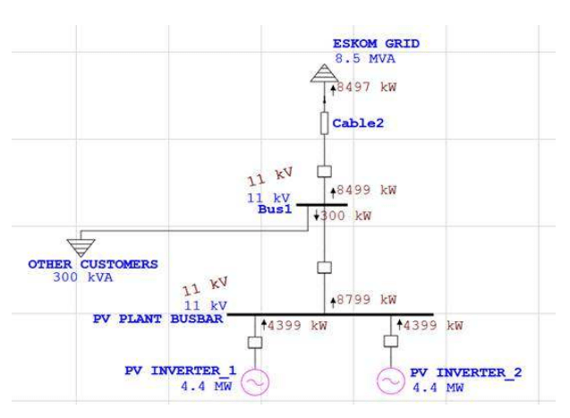
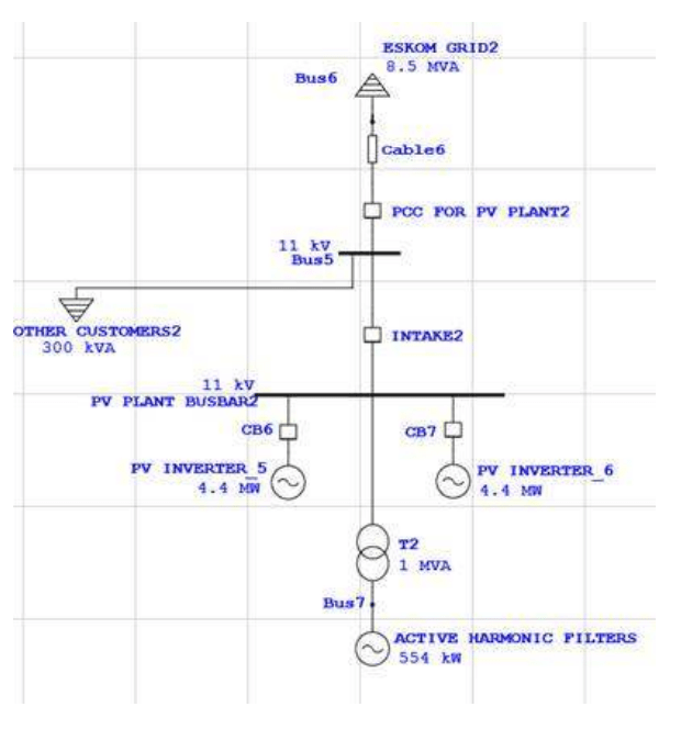
An infrequently implemented feature of these two plants is the plant infeed connection to grid at MV levels (11 kV and 22 kV respectively); the connection busses in both cases are also shared with other users/customers at MV level. Measurements at the PCC (the contractual evaluation point) therefor included potential adverse PQ contribution from these foreign users; this contribution is not dampened via any additional impedance element (i.e. a MV/HV transformer) as typically the case for RPPs where the PCC is at HV (132 kV) level. A representative high level single line distribution diagram (SLD) is presented in Fig. 1.
Grid code compliance studies therefor required either a means of separation in the PQ recordings of the PV-plant only from those of all other shared PCC users, (this to prove PV-only contribution to the grid), or otherwise the provision for adequate mitigation to cater for contribution of all connections at the PCC.
Constant variation in the harmonic spectrum
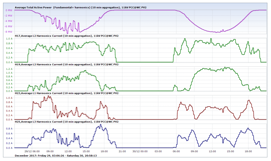
Extended PQ recordings of the PV plants under typical operations revealed excessive harmonic content at varying frequencies. For example, harmonic content during early morning and evenings (start-up and shutdown periods) proved to be very different from the harmonic recordings during full operation (midday) periods. This phenomenon is largely influenced by the characteristics of the PV string invertors’ functionality and control setup. Likewise, influences of cloud activity gave rise to yet another set of characteristic harmonic content. This is demonstrated in Fig. 2; the left side of the graph represent a day with varying cloud coverage, while the right-hand side is typical of a ‘normal’ open sky day period. Harmonic current for the orders 17th, 19th, 23rd and 25th are shown; these just so happen to be the offending harmonic orders due for mitigation. Such variation in harmonic content characteristics dictates special attention with respect to the suitable alternative technologies for effective mitigation.
Mitigation solution
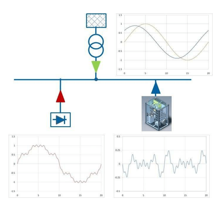
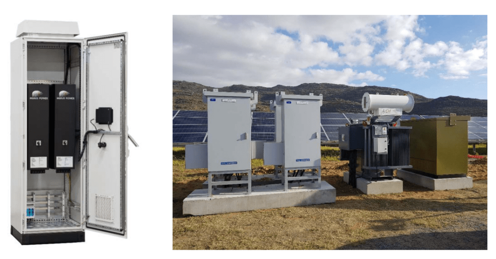
Amongst the alternative harmonic mitigation options for these reference case PV plants, an active harmonic filter (AHF) solution technology was opted for. Such a solution is based on the real-time measurement of harmonic content and the then very fast (within 1ms) generation and injection of cancelling harmonic current. A typical example of the injected waveform can be seen in Fig. 3; for the reference sites this compensation signal was implemented at a single injection point for the complete plant at 400V level, therefor also mandating the installation of a singular suitable size step-up transformer as can be seen in Fig 4. Special design of the active filter needed to occur to ensure the impedance of the transformer did not negatively affect the compensation.
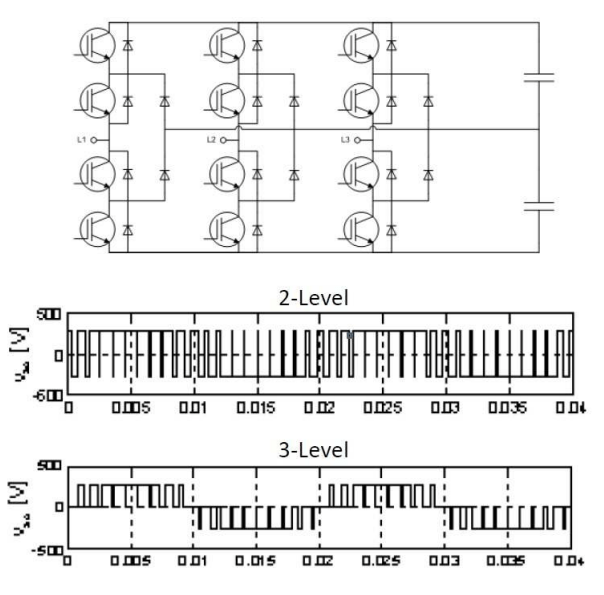
The active filters installed were of three level switching topology which can be seen in Fig. 6; this topology allows for much greater resolution on the measurements and compensation of the harmonics. The higher capacity in turn allows for compensation of much higher harmonic orders. Three level topology also has reduced losses and there is lower stress on the DC-link capacitor. These were all factors that allowed for the compensation of the harmonics required by the reference plants.
Renewable Plant existing compliance
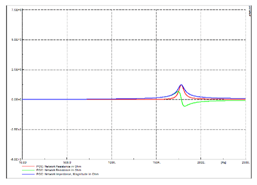
As the AHFs are installed after the plant is operational there were existing compliance specifications that should not be interfered with. These include the reactive power flow of the plant and network resonance with the grid (Fig 7). The AHF equipment manufacturer was able to provide a solution whereby the filter is able to compensate both harmonics and 50Hz reactive power simultaneously should it be necessary to reduce the impact of the step-up transformer in the filter circuit. The implementation of the solution also aided in the reduction of resonance (Fig 8) with the grid with the added impedance to the system. This should be checked prior to the installation by the filter designer in conjunction with the plant owner’s engineer.

Filter configuration
It is common practice for OEMs to provide AHFs in predetermined unit sizes (e.g. 50 A or 100 A sizes). Where higher levels of compensation are required, multiple units can be configured in parallel (where all units are targeting all offending harmonic frequencies), or individual AHF units may each be directed at specific offending harmonic order(s) only. In practice, the playoff of these different combinations in weighing up redundancy with broadband mitigation advantages are important considerations in the final filter control-setup configuration. It is noteworthy that a thorough knowledge of network characteristics (which can only be obtained from prolonged actual recordings) plays a major role in the above decisions. Such knowledge also allows for optimized mitigation in the sense that compensation is only required up the levels of safely being within the allowable set limits for most eventualities (i.e. it is normally not necessary to eliminate all off the harmonic content).
Transformer design parameters
It would be appreciated that the transformer duty requirements for the above include satisfactory harmonic current transfer duty. In contrast to a normal distribution transformer which is primarily earmarked for 50 Hz duty, this application calls for either suitable K-factor rated (preferable) and/or other specific means of allowing for heat generation due to skineffect current distribution in the internal transformer conductors.
Summation CT’s requirements
Following onto the above paragraphs, the correct selection of CTs (and summation CTs) are paramount to satisfactorily performance of the AHFs. Frequency response, burden, transfer ratios and physical sizes are all to be carefully considered.
Environmental conditions
From an environmental perspective, the ambient temperatures at the reference sites prove to be a challenge for reliable operation of electronic equipment; recorded temperatures over extended periods (many months) were found to regularly in the region of between 40-45°C. This relates to special demands on electronic components’ protection mechanisms, including cooling and heat flow design aspects of equipment containers.
Observations beyond grid code regulation requirements
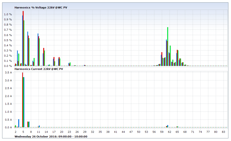
Extensive recordings at other reference plants included relevant data at harmonic orders far beyond the regulatory requirements of only up to the 50th harmonic order. (The actual recordings were performed up to the 512th harmonic order). Fig. 9 for example provides insight into harmonic content between the 60th and 70th harmonic orders; voltage recordings (in %) at the PCC bus and current recordings (in Ampere) from the feeder line where the PV plant taps into the PCC bus. The poor correlation of voltage to current content above the 50th is indicative of the likelihood that this is background (i.e. grid related) or non-PV plant related harmonic content. (This particular recording over about an hour period was taken under stable PV plant operational conditions.)
Being outside the scope of regulation requirements, and indeed outside the capability of most commercially available PQ recorders, this higher (50th +) order harmonic content therefor very seldom gets noticed, let alone acted on. The authors of this article had the privileged of being actively involved in the very detailed and high-resolution recording exercises at numerous and widespread grid connection locations (including more than two dozen renewable plants grid connection studies), and this phenomenon was witnessed at several geographical places across the country. It is therefor proposed that regulators also be sensitised to this growing phenomenon (of the above 50th harmonic pollution of the grid), and the possible implications (if any) of such for nearby consumers also to be considered in future regulatory matter.
Summary
This article summarises some of the challenges which may be experienced in the process of obtaining QoS compliance towards grid code connectivity for utility scale renewable plants in South Africa. The use of active harmonic filters (AHF) proved to be a viable solution to adequately mitigate the constantly varying nature of offending harmonic orders up to (at least) the 35th harmonic order. It furthermore highlights the fact that the harmonic content beyond the 50th harmonic order (i.e. outside the scope of current regulatory codes) is increasing evident on the South African national grid; the future implications thereof perhaps not fully realised yet.
References
[1] Grid Connection Code for Renewable Power Plants (RPPs) connected to the Electricity Transmission System (TS) or the Distribution System (DS) in South Africa, Version 2.9, July 2016.
Contact details: Dirk van der Bank, dirk@adaee.co.za/ Kyle Lass, kjlass@rwww.co.za
Published: Energize, July 2018
