Published by Michał PIEKARZ, Politechnika Warszawska, Instytut Elektroenergetyki
ORCID: 0000-0003-1500-2634
Abstract. The article discusses the issues related to the influence of connecting wind turbines on the angular stability of the power system. Current plans for Poland’s energy transition, climate issues, and the most popular types of wind turbines used in the world were discussed. In the study part, the impact of replacing traditional generating units with wind turbine systems connected by converters on the angular stability of the New England test model was analysed.
Streszczenie. W artykule zostały omówione zagadnienia dotyczące wpływu przyłączania turbin wiatrowych na stabilność kątową systemu. Omówiono aktualne plany dotyczące transformacji energetycznej Polski, kwestie klimatyczne, a także najpopularniejsze rodzaje turbin wiatrowych, wykorzystywanych na świecie. W części badawczej przeanalizowano wpływ zastępowania tradycyjnych jednostek wytwórczych układami turbin wiatrowych przyłączanych przez przekształtniki na stabilność kątową modelu testowego systemu New England. (Analiza wpływu generacji wiatrowej na stabilność systemu elektroenergetycznego)
Słowa kluczowe: stabilność kątowa, generacja wiatrowa, inercja systemu elektroenergetycznego, analiza wartości własnych.
Keywords: angular stability, wind generation, power system inertia, eigenvalue analysis.
Introduction
Along with the economically and technologically developing society, the arises issues will have to be solved in the next few years. Continuous economic development, and thus an increase in energy demand, will not be the only problem that power systems will be facing. The dynamics of the increase in electricity demand [1], climate change and excessive carbon dioxide emissions must be considered [2]. One of the solutions to the above problems can be renewable energy sources. The European Union’s climate and energy policy will, in general, strive for climate neutrality as early as 2050 [3].
One of the main pillars of this policy is, among others, changing the energy mix with an increased share of renewable sources [4].
Increasing number of generating units, connected to the system by converters may cause problems related to the stability or decreasing inertia of the power system [5]. The aim of this article is to present research on replacing traditional generating units with wind farms, as well as assessing their impact on the angular stability of the system.
Climate and energy
The climate and energy policy of the European Union (EU) has a fundamental impact on the national energy strategy, including the long-term vision of achieving the EU’s climate neutrality by 2050 [6,7]. Along with the dynamic economic development that Poland has been experiencing for 30 years, the demand and generation of energy is also increasing. In the case of gross domestic energy consumption, coal plays a central role in Poland – in 2018 it accounted for 46% of the share. Then petroleum (29%), natural gas (15%) and renewable energy sources (9%) [8].
At the same time, excessive carbon dioxide emissions in the electricity sector [1] and climate change around the world, cause the growth of generation from renewable energy sources (RES) [9].
Achieving the climate and energy goals by 2030 is extremely important to accomplish the required low emission energy transformation. In December 2020, the European Council approved targets to reduce net greenhouse gas emissions to at least 55% compared to 1990 levels [3].
The Energy Policy of Poland until 2040 (PEP2040) formulates the scope of the energy transformation in Poland. It specifies, among others, range of technology selection aimed at development of a low-emission power system. The key assumptions of the PEP2040 document regarding the power industry mention [6]:
• Increase in the share of RES in all sectors and technologies. In 2030, the share of RES in gross final energy consumption will be at least 23%, including: no less than 32% in electricity (mainly wind and PV); 28% in heating; 14% in transport (with a large contribution of electromobility).
• The installed capacity of offshore wind energy will be approx. from 5.9 GW in 2030 to approx. 11 GW in 2040.
Wind Energy in Poland
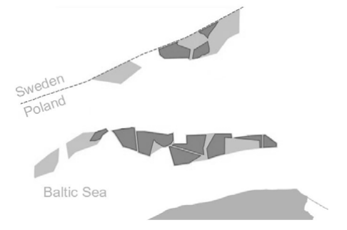
At the end of 2020, the installed capacity of onshore wind was 6347 MW [10]. Also in 2020, the act on supporting offshore wind farms was passed [7]. Subsequently, the European Commission approved the rules of public aid, and all the effort was dedicated on implementing regulations. It was all for the purpose of ensuring that electricity from offshore farms in the Baltic Sea will flow to customers by the end of 2025. The Fig. 1 shows the location of the offshore wind farms in the Polish part of the Baltic Sea, where the most important projects are marked with dark gray color [11].
According to the PEP2040, two scenarios for wind farms in Poland have been proposed – base and ambitious scenario. The base scenario assumes that 10 GW of installed onshore and 5.9 GW of offshore capacity will be achieved by 2030, and 10 GW of onshore and 11 GW of offshore capacity by 2040. The ambitious scenario assumes 18 GW of installed capacity onshore and 5.9 GW at sea will be achieved by 2030, and 25 GW by 2040 on land and 14- 15 GW at sea. The wind energy for 2020 is as follows: 6.35 GW of installed capacity on land, 16 TWh of electricity production and 1239 installations [8,12].
Wind turbine types
The types of wind turbines that are used in currently operating wind farms are shown in Fig. 2. Variable speed wind turbines are equipped with DFIG (Doubly-fed Induction Generator) or full converter generators with PMSG (Permanent Magnet Synchronous Generator). This is due to the better control properties, compared with constant speed wind turbine generators (induction generators). In the case of DFIG generators, their advantage is that only 30% of the power flows through the circuit with the converter. In the case of a synchronous generator (PMSG), the converter must be sized for the full power of the generator. Synchronous generators are more efficient and have a simpler structure, but their cost is higher. In the case of DFIG generators, it is necessary to use additional protection systems against current surge in the event of damage.

Influence of wind farms on the dynamics of the power system
High penetration of a power-electronic connected generators, and therefore decommissioning of generation units with rotating masses, can decrease the system inertia. Traditional generation is based on large turbo or hydro generation units. These units make a significant amount of inertia in the system which is very important for maintaining power system stability. After a power loss, the resulting system frequency drop is delayed by rotating inertia of such generation units [5].
Renewable generation, such as Photo-voltaic systems and wind turbines, are connected through the power electronic devices. This way of connecting generation results in no additional inertia in the power system.
There is a concern that the rate of change of frequency (RoCoF) will increase, and the system stability will be endangered. On Fig 3, there are four elements with high impact on electrical power systems such as: extension of grids (which can affect inter-area oscillations), weather phenomena, large power flows and the market effects.
Then another factors must be considered such as load behaviour (e.g., inverters) and load control. These elements, together with decreasing inertia, can affect frequency behaviour and the value of the inter-area oscillations damping.

Model of the New England power system
The analysis for this article was performed based on the 39 Bus New England System network model (Fig. 4). It is a simplified model of the high voltage network of the Northeast United States [13]. It consists of 39 nodes, 10 synchronous generators, 19 loads, 34 lines and 12 transformers. It uses a rated frequency of 60 Hz, and the highest voltage level is 345 kV. There are also voltages such as 230 kV, 138 kV and 16.5 kV. The G10 generator represents the interconnection of US and Canadian systems. The remaining generators are connected via transformers to the network.
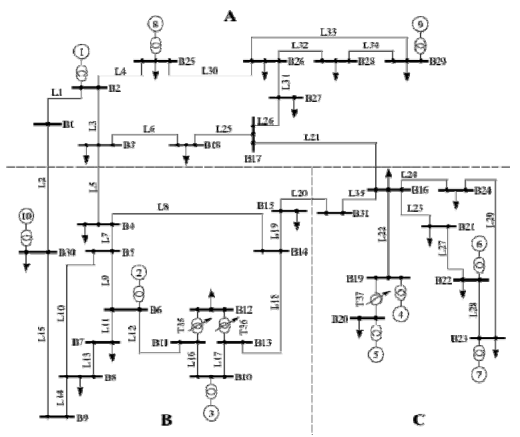
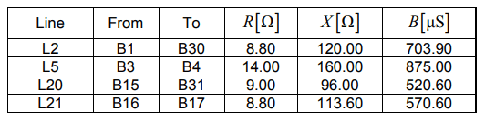
For the purposes of the research, in the field of interarea oscillations, the length of four lines in the model was increased by changing the basic parameters – resistance, reactance and susceptance. The following lines were extended: L2 connecting nodes B1 and B30, L5 – nodes B3 and B4, L20 – nodes B15 and B31 and L21 – nodes B16 and B17. The new parameters of the lines are presented in Table 1.
Table 1. Parameters of the modified line sections
Method and plan of the analysis
This article presents the results of the local angular stability analysis of the power system. The research was carried out in the Power Factory software. For this purpose, the modal analysis module was used to determine the eigenvalues, the oscillation frequencies, and the damping coefficients.
For small perturbations, the system can be expressed in linearized form as follows [16]:
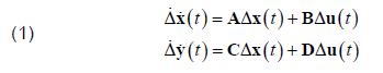
where: Δ is the prefix which denotes a small deviation, A is the state or plant matrix, B is the control input matrix, C is the output matrix, D is the matrix, which defines the proportion of input which appears directly in the output.
The eigenvalues of the state matrix A determine the time domain response of the system to small disturbances. From state matrix A we can calculate the eigenvalues which can determine the stability of the system. For a complex pair of eigenvalues λ = σ ± jw , the real component gives the information about damping and the negative values represents a damped oscillations. The frequency oscillations f in Hz is given by:
and the damping ratio ξ is given by:
The research program was divided into the following cases:
• Case 1 – the basic model of the system with extended lines L2, L5, L20 and L21.
• Case 2 – in the basic model, the traditional G03, G07 and G09 generation units were replaced with wind generation units of the full-converter type.
• Case 3 – in the basic model, traditional generation units located in area C were replaced, i.e., G04, G05, G06 and G07 (Area C becomes non-inertia).
Additionally, the model from Case 3 investigated the effect of installing additional synchronous units along wind turbines.
The results of the analysis
a) Case 1
The research starts with the analysis of the basic case 1 i.e., identification of electromechanical oscillations. As part of this study, the eigenvalues related to local and inter-area oscillations were distinguished, as well as the oscillation frequencies and damping coefficients. The results for the Case 1 are presented in Table 2.
In the Case 1, eigenvalues related to inter-area oscillations were distinguished – 50, 51 and 54, 55. The generators G02 (50, 51) and G09 (54, 55) had a dominant share in these specific eigenvalues.
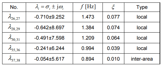
b) Case 2
In the Case 2, the synchronous generators G03, G07 and G09 were replaced by the wind generators. Compared to the Case 1, the Case 2 had eigenvalues related to interarea oscillations – 37, 38. In those eigenvalues, the interarea oscillations are dominated by the G10 generator, with the oscillation frequency slightly increased (from 0.807 to 0.894), and the damping factor decreased (from 0.030 to 0.010). The results for the Case 2 are presented in Table 3.
Table 2. The results for the Case 1
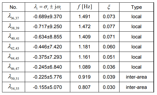
Table 3. The results for the Case 2
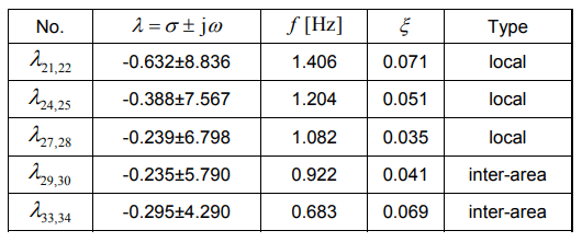
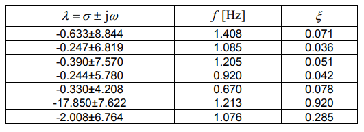
c) Case 3
In Case 3, synchronous generators that were located in the C sector of the New England system were replaced by the wind turbines. In the Case 3, there are four eigenvalues related to inter-area oscillations – 29, 30 and 33, 34. As in the Case 1, the dominant generators in these eigenvalues are the generators G02 (29, 30) and G09 (33, 34), respectively. Compared to Case 1, the oscillation frequency related to the G02 generator remained practically the same (from 0.919 to 0.922) and for generator G09, the frequency oscillation decreased (from 0.807 to 0.683). The damping factor for generator G02 remained practically unchanged (0.039 to 0.041), while for G09, the damping factor increased (0.030 to 0.069). The results for the W3 variant are presented in Table 4.
Table 4. The results for the Case 3
d) Additional analysis for Case 3
In the next part, the Case 3 was extended by four additional cases 3 (G4), 3 (G5), 3 (G6), and 3 (G7). In each of them, in the place of the synchronous generator replaced by the wind turbine, an additional inertia was introduced i.e., a synchronous source that would contribute to the system inertia.
The results of the Case 3 with additional inertia at the location of the generator G4 are presented in Table 5. Table 6 presents the results for the Case 3 with additional inertia at the location of the generator G5. Table 7 presents the results for the Case 3 with additional inertia at the location of the generator G6. Table 8 presents the results for the Case 3 with additional inertia at the location of the generator G7.
Table 5. The results for the Case 3 (G4)
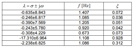
Table 6. The results for the Case 3 (G5)
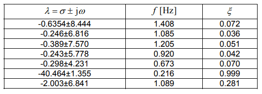
Table 7. The results for the Case 3 (G6)
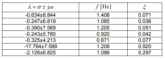
Table 8. The results for the Case 3 (G7)
Compared to Case 3. the number of eigenvalues in the field of electromechanical oscillations increased by 4, while the effect of connecting an additional inertia had little impact on the eigenvalues of the system. However, a change can be seen in the case of eigenvalues related to the added inertia (last two rows). In the Case 3 (G5), a reduction in the oscillation frequency from approx. 1 Hz to 0.216 Hz can be noticed. The damping factors did not change much.
Summary
The article presents current issues related to renewable energy sources – energy transition, Poland’s energy policy until 2050, and the current state of wind energy. The issue of integration of renewable energy units connected to the system by converters was discussed.
The results of the local angular stability studies for various cases of replacing conventional sources with wind sources were presented. The tests were carried out on a model of the New England power system. The base model was modified, the length of four lines was increased. Then, three cases of research were proposed, in which traditional generating units were replaced by wind turbines. An analysis of connecting additional inertia at the wind farm location was also performed.
The obtained research results confirm that the transformation of the generation sector of the power system has an impact on the dynamics of the power system.
REFERENCES
[1] Rabiega W., Sikora P., Gąska J., CO2 Emissions Reduction Potential in Transport Sector in Poland and the EU Until 2050, 2019.
[2] Luboińska B., Emisja gazów cieplarnianych. Wybrane zagadnienia dotyczące emisji CO2 w Polsce. Opracowanie tematyczne OT-683, Kancelaria Senatu, 2020.
[3] Wolf S., Teitge J., Mielke J., Schütze F., Jaeger C., The European Green Deal — More Than Climate Neutrality, Intereconomics, vol. 56, no. 2, pp. 99–107, Mar. 2021.
[4] Paska J., Surma T., Electricity generation from renewable energy sources in Poland, Renewable Energy, vol. 71, pp. 286–294, 2014.
[5] Entso-E, Inertia and Rate of Change of Frequency (RoCoF), 2020.
[6] Polityka Energetyczna Polski do 2040 r., 2021.
[7] Minister Kurtyka on RES in the Polish energy mix, https://www.gov.pl/web/climate/minister-kurtyka-on-res-in-thepolish-energy-mix.
[8] Ceglarz A., Polska Polityka energetyczna, 2020.
[9] Marks-Bielska R., Bielski S., Pik K., Kurowska K., The importance of renewable energy sources in Poland’s energy mix, Energies, vol. 13, no. 18, 2020.
[10] Urząd Regulacji Energetyki, https://www.ure.gov.pl/.
[11] Polskie Stowarzyszenie Energetyki Wiatrowej, Przewodnik po systemie wsparcia dla morskich elektrowni wiatrowych na Bałtyku, 2020.
[12] TPA Poland, Baker Tilly TPA, Lądowa energetyka wiatrowa w Polsce, Onshore wind energy in Poland – Raport, 2021.
[13] Digisilent PowerFactory, 39 Bus New England System Manual.
[14] Łukasz N., Sylwester R., Machowski J., Control Algorithm for UPFC Based on Non-linear Model of Power System, Electric Power Components and Systems, 47, ISSN 1532-5008, pp. 605-618, 2019
[15] Skwarski M., Robak S., Piekarz M., Polewaczyk M., MultiObjective Optimal Sizing of Shunt Braking Resistor for Transient State Improvement, IEEE Access, vol. 9, pp. 69127-69138, 2021.
[16] Machowski J., Bialek J.W., Bumby J.R., Power System Dynamics Stability and control, Second Edition John Wiley&Sons, Chichester, 2008.
Autorzy: mgr inż. Michał Piekarz, Politechnika Warszawska, Wydział Elektryczny, Instytut Elektroenergetyki, ul. Koszykowa 75, 00-662 Warszawa, E-mail: michal.piekarz@ien.pw.edu.pl.
Source & Publisher Item Identifier: PRZEGLĄD ELEKTROTECHNICZNY, ISSN 0033-2097, R. 97 NR 11/2021
