Published by Stanilav S. Girshin1, Igor A. Sorokin2, Aleksandr N. Smerdin3, Aleksandr AY. Bigun1, Elena V. Petrova1, Vladislav M. Trotsenko1, Vladimir N. Goryunov1, George S. Smorodin1,
Omsk State Technical Univercity, Omsk, Russia (1)
Public Join Stock «Interregional Distribution Grid Company of Siberia» (2)
Omsk State Transport University, Omsk, Russian (3)
Abstract. The influence of solar radiation on the temperature regimes of power lines implemented with classical and new types of wires is considered. The maximum permissible temperatures limit the capacity of the lines, and the current temperature regime affects the loss of power and energy due to changes in the ohmic resistance. The paper presents the heat balance equations for insulated and non-insulated wires, formulas for calculating the heat transfer coefficient and solar radiation intensity, and an expression for the permissible current. Typical values of direct and diffused radiation are compared, provided that the wire is perpendicular to the sunlight. It is shown that solar radiation leads to an increase in the temperature of the wires by 5 and up to 7 degrees Celsius with a weak dependence on the type of wires and current load. The corresponding increase in real-power losses does not exceed 3%. The results obtained with the proposed technique for non-isolated wires show good convergence with previous studies. One of the advantages of the developed method is its versatility, which is manifested in the possibility of its application not only for non-insulated wires, but also for wires with insulation.
Streszczenie. Analizowany jest wpływ promieniowania słonecznego na warunki temperaturowe linii energetycznych z klasycznymi i nowymi typami drutów. Maksymalne dopuszczalne temperatury ograniczają możliwości linii, a warunki temperaturowe wpływa na utratę mocy i energii z powodu zmian rezystancji. W pracy przedstawiono równania bilansu cieplnego dla drutów izolowanych i nieizolowanych, wzory do obliczania współczynnika przenikania ciepła i natężenia promieniowania słonecznego oraz wyrażenie na dopuszczalny prąd. Porównywane są typowe wartości promieniowania bezpośredniego i rozproszonego, pod warunkiem, że drut jest prostopadły do światła słonecznego. Analizą efektu promieniowania słonecznego na możliwości i straty mocy napowietrznych linii energetycznych
Keywords: heat balance equation, overhead power lines, temperature regime, real-power losses.
Słowa kluczowe: równanie bilansu cieplnego, napowietrzne linie energetyczne, straty mocy rzeczywistej.
Introduction
One of the conditions for the optimum operation of electric power networks is to minimize the loss of electric energy [1-4]. An assessment of the loss reduction effectiveness requires accuracy in loss determination, this being of particular importance [5]. It is necessary to consider temperature dependence of the ohmic resistance in improving the accuracy of loss calculation [ 6-10]. The wire temperature depends on the wind pattern, air temperature, current load, atmospheric pressure, and solar radiation [11-13]. The influence of solar radiation on the wire temperature is presented in detail in the paper [14, 15]. It is indicated that solar radiation significantly affects unloaded wires. The temperature in this case may increase by 10 to 12 °C. For current density of 2 A/mm2 the heat caused by solar radiation does not exceed 3 to 5 °C. It is noted that in temperate latitudes the solar energy can increase the temperature of the wire operated in the range of permissible temperatures by 2 to 3 °С. In southern latitudes with an ambient temperature of 45 °C in clear weather, heating of the wire by solar radiation can reach 15 or 16 ° C. A more significant increase in the wire temperature in clear weather from exposure to solar radiation (up to 22.5 °C) is noted in the research of OAO Nauchno-Issledovatelsky Institut Electroenergetiki (VNIIE), a publicly held company under the laws of the Russian Federation [16]. The paper [16] indicates that solar radiation heating of the wire can be ignored in winter. Nevertheless, as modern research shows, the solar radiation power at the receiving platform at different angles and in the winter months can be of the same order as the radiation in the summer months.
Heat balance equations used
The above results were obtained in studies of traditional AS wires. This paper presents studies of modern high temperature and self-supporting insulated wires of overhead power lines. The temperature of an insulated wire in a steady-state regime can be found based on the heat balance equation per unit length of the power line [17].
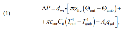
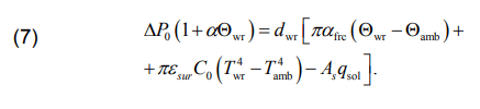
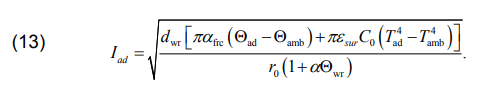
where ΔP are the real-power losses in the wire per unit length at a temperature of Θwr; dwr is the wire diameter; αfrc is the forced convection heat transfer coefficient; Θout and Θamb respectively are the temperature of the wire outer surface and ambient temperature, °С; εsur is the emissivity factor of the wire surface for infrared radiation; C0 = 5,67·10- 8 W/(m2 ·К4 ) is the black body radiation constant; Tout and Tamb are respectively the absolute wire surface temperature and ambient temperature; As is the absorptivity of the wire surface to solar radiation; and qsol is the solar radiation flux density to the wire.
The formulas [17, 18] are used to determine αfrc, Sins, qsol:
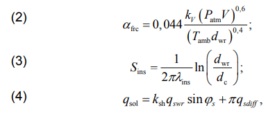
where kV is the wind attack angle coefficient; Patm is the atmospheric pressure; V is the wind speed; Sins is the thermal resistance of insulation; λins is the coefficient of insulation thermal conductivity; dc is the diameter of conductor wire; ksh is the coefficient of line section shading; qswr is the flux density of direct solar radiation on the surface perpendicular to sunlight; φs is the angle between the wire axis and the direction of sunlight; qsdiff is the flux density of diffused solar radiation.
Direct solar radiation varies throughout the year and during the day, so half the value of solar radiation on the earth’s surface was used to account for the effects of solar radiation. The maximum value of direct solar radiation is estimated at 1000 W / m2 . The annual and daily change also occurs for diffused radiation. An average value of 100 W / m2 based on the obtained data is used for calculations. The shading factor ksh is taken to account for the length of the line that is on average illuminated by the sun during the daytime. Since, as a rule, most electric power lines are operated far from high structures, the ksh value is assumed to be 1. For 10 kV lines, the ksh can be less due to the proximity of utility systems. For 110 kV lines with high supports, it is permissible to increase the ksh.
In actual use, the angle φs is determined by the average azimuth of the wire and the latitude. In this paper, the maximum value of φs = 90° is assumed, which is observed at noon when the wire is positioned from West to East.
The value ∆Р is determined by the relations:
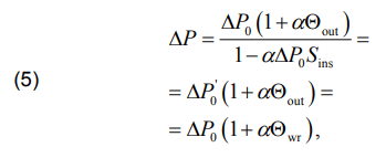
where ΔP0 = I2r0 is the real-power losses in the wire per unit length at the temperature of 0°С; I is the current in the wire; r0 is the in -length ohmic resistance at the temperature of 0 °С; α is the temperature coefficient of resistance; Θwr is the wire temperature.

Equation (1) is obtained assuming that the temperature gradient inside the wire core is equal to zero, i.e. grad Θwr = 0. From this condition we write

The temperature of the non-insulated wire and the real-power losses can be conducted on the basis of 1 at Sins= 0. In this case we obtain
Study of the influence of solar radiation on wires
Relations (1) – (7) were used to study the behavior of three types of wires:
• non-insulated wires ACSR-240/40;
• self-supporting insulated wires PAS-W 1×95;
• high-temperature non-insulated wires ACCR-470-T16.
The arrangements of the wires selected for the numerical experiment (table 1) are shown in fig. 1.
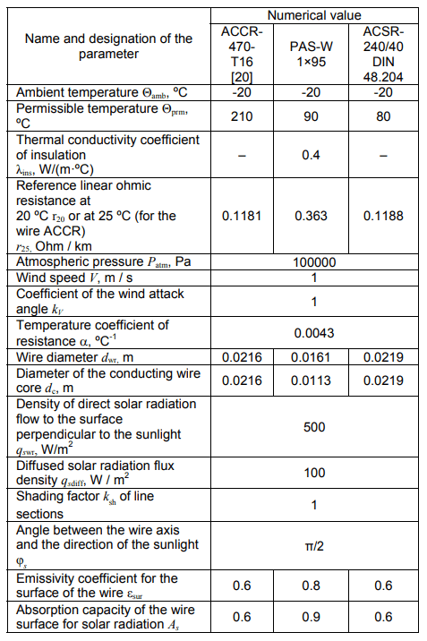
Table 1. Conditions of the numerical experiment
Tables 2, 3, 4 and fig.s 2, 3, 4 represent various aspects of studying real-power losses and temperature losses for the specified types of overhead line wires, with or without solar radiation.
The ambient temperature is assumed to be -20 °C (tables 2, 3, and 4).
The notation shown in tables 2, 3, and 4 correspond to the following formulas
where ΔΘwr, ΔΘ, ΔΘout are temperature differences corresponding to the formulas (8), (9), and (12); ∆Рр and ε∆Р are the absolute and relative differences in real power.
The “s” index in the formulas indicates solar radiation taken into account.
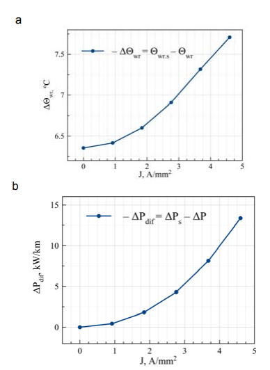
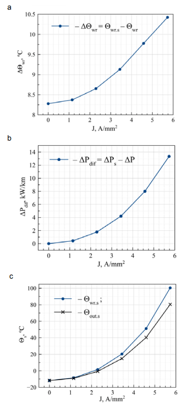
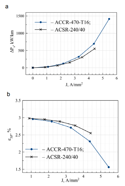
The nature of the graphs in fig. 2 indicates, on the one hand, the excess of the real power and temperature for the wire ACSR-240/40 in the case of solar radiation. When the current density J changes, the ranges of excess real power and temperature are from 0.442 to 13.366 kW/km and from 6.354 to 7.763 °C, respectively (table 2). On the other hand, this excess is not very large. The maximum relative excess of ε∆Р is 2.98 %. The maximum core temperature excess is 7.763 °C.
A special feature of the graph is the increase in the difference between the losses of the ∆Рdif and the temperature difference ∆Θwr of the wire with an increase in the current density (fig. 2). This feature can be explained as follows.
Table 2. Results of the numerical experiment for the wire ACSR-240/40 at Icalc prm = 1104.6 A
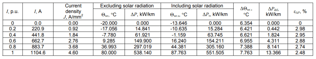
Table 3. Numerical experiment results of the wire PAS-W 1×95 with Icalc prm = 544.81 A
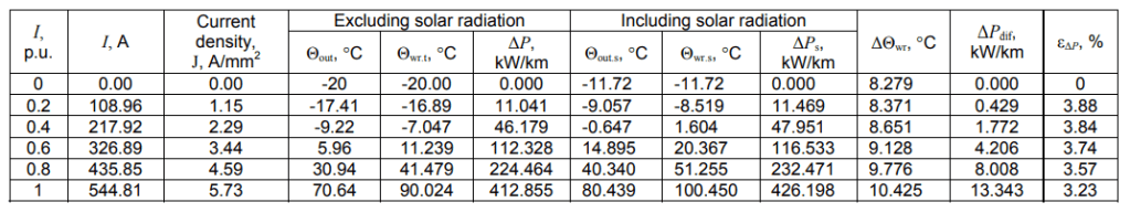
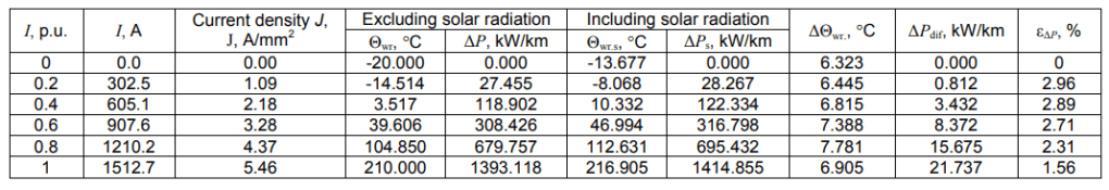
Table 4. Numerical experiment results for the wire ACCR-470-T16 with Icalc prm = 1512.7 A
Any increase in the temperature of the wire, regardless of its cause, leads to an increase in real-power losses (heat generation) due to an increase in resistance. As a result, there is even greater increase in temperature. Thus, there is a positive feedback, which is stronger when the current density is higher (as the losses increase by 1 degree). In other words, at high currents any heating enhances itself to a greater extent than at low currents. In this case, heating caused by solar radiation plays the role of additional heating.
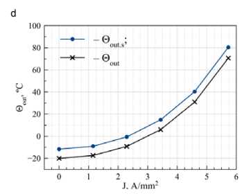
For the wire PAS-W in general we have a similar picture (fig. 3a, b). The changes relate to a slight quantitative increase in ΔΘwr, ΔРdif, εΔР. The maximum value for ΔΘwr is 10.425 °С and for ΔРр it is 13.343 kW/km, and for εΔР it is 3.88 % (table 3).
The value ε∆Р for all the wires under consideration is close to 4 %. The fact is shown in the graph in fig. 4b. At the same time, differences in the values of permissible currents and ambient temperatures cause certain differences in the quantitative changes in the values ΔРs. The permissible current Iprm for the non-insulated wire ACSR in the case of forced convection, based on equation (7), is proposed to be determined by the formula:
Insulation in the wire PAS-W makes it possible to increase the number of parameters under study. Various aspects of the study are shown in fig. 3. All the dependencies have a corresponding physical interpretation.
In particular, in fig. 3b, the discrepancy increase of Θwr s and Θout s with increasing current density corresponds to equation (6).
Table 4 and fig.s 4a and 4b show the change trends of ΔΘwr and ΔРdif for the wires ACSR-470-T16 and ACSR240/40 corresponding to the change trends for the wire PAS-W (Iprm = 544.81 A). The calculations with the AС wires (the analog of ACSR) and СИП-3 (the analog of PAS-W) manufactured in Russia showed almost complete identity of the graphs in fig.s 2, 3 and 4 in terms of the form and parameter values.
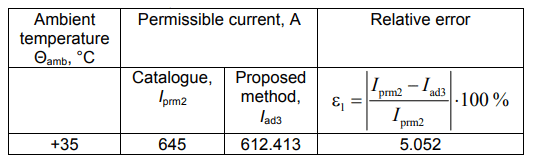
The comparison for the ambient temperature of +35 °C is given in table 5. The relative error is insignificant and it is 5.052 %.
Table 5. Comparison of the calculated values of the permissible current for the wire ACSR-240/40 with the permissible current calculated according to the catalog [19] at the ambient temperature Θamb = +35 °С and the wire temperature Θamb = +80 °C, the wind speed: V = 0.6 m / s, including solar radiation
Conclusion
The following conclusions can be drawn from the research.
1. For the types of wires and ambient temperature values considered in this paper, solar radiation taken into account leads to an increase in real-power losses by up to 3.88%. The maximum increase corresponds to the wire PAS-W 1×95 at a current of 32% of the permissible one. The relative differences in the real-power losses calculated with or without solar radiation are slightly reduced when the current load increases. However, the same differences in kW/km, conversely, increase.
2. As the current density increases, the difference in wire temperatures calculated with or without solar radiation generally increase. The maximum increase in the temperature difference is 10.425 °C and corresponds to the wire PAS-W.
3. For the standard ACSR-240/40 wire, a high coincidence of permissible current calculation data according to the proposed method with the value of the permissible current from the catalogue [19] was determined. The relative error does not exceed 5.052 %.
4. The developed method is applicable not only for standard non-insulated ACSR wires, but also for expanded capacity wires and self-supporting insulated wires.
REFERENCES
[1] Kowalski J., Jak pisać tekst do Przeglądu, Przegląd Elektrotechniczny, 78 (2002), nr 5, 125-128
[2] Johnson B., Pike G.E., Preparation of Papers for Transactions, IEEE Trans. Magn., 50 (2002), No. 5, 133-13
[1] Kukharchuk I. B., Kazakov A. V., Trufanova N. M. Investigation of heating of 150 kV underground cable line for various conditions of laying // Materials Science and Engineering. 2018. No. 327. P. 1-6. DOI 10.1088/1757-899X/327/2/022041.
[2] A. O. Shepelev, E.V. Petrova, O.A. Sidorov, “Consideration of Active Resistances Temperature Dependency of Power Transformers when Calculating Power Losses in Grids”, Industrial Engineering Applications and Manufacturing (ICIEAM) 2018 International Conference on, pp. 1-5, 2018.
[3] Lobão J. A., Devezas T., Catalão JPS. Reduction of greenhouse gas emissions resulting from decreased losses in the conductors of an electrical installation // Energy Convers Manage. 2014. Vol. 87. P. 787–95. DOI: 10.1016/j.enconman.2014.07.067.
[4] Wiecek B., De Mey G., Chatziathanasiou V. [et al.]. Theodosoglou I. Harmonic analysis of dynamic thermal problems in high voltage overhead transmission lines and buried cables // International Journal of Electrical Power & Energy Systems. 2014. Vol. 58. P. 199–205.
[5] Girshin, S.S., Bigun, A.A.Y., Ivanova, E.V., Petrova, E.V., Goryunov, V.N., Shepelev, A.O. The grid element temperature considering when selecting measures to reduce energy losses on the example of reactive power compensation // Przeglad Elektrotechniczny. 2018. No. 8. P. 101-104. DOI 10.15199/48.2018.08.24.
[6] Girshin, S.S., Kropotin, O., Trotsenko, V.M., Shepelev, A.O., Petrova, E.V., Goryunov, V.N., Simplified formula for the load losses of active power in power lines taking into account temperature// Przeglad Elektrotechniczny. 2019. No. 7. P. 42-46. DOI 10.15199/48.2019.07.10
[7] S.L. Chen, W. Z. Black, H. W. Loard, “High-temperature ampacity model for overhead conductors”, Power Delivery IEEE Transactions on, vol. 17, no. 4, pp. 1136-1141, Oct. 2002.
[8] J., Teh, I., Cotton Critical span identification model for dynamic thermal rating system placement // IET Generation, Transmission & Distribution. 2015. Vol. 9, Iss. 16, pp. 2644–2652. DOI: 10.1049/iet-gtd.2015.0601
[9] Shchebeniuk L. A., Antonets T. Yu. Investigation of losses in insulation of high-voltage cables with XLPE insulation // Electrical Engineering & Electromechanics. 2016. No. 4. P. 58–62. DOI 10.20998/2074-272X.2016.4.08.
[10] Łukasz Topolski, Jurij Warecki, Zbigniew Hanzelka Methods for determining power losses in cable lines with nonlinear load // Przeglad Elektrotechniczny. 2018. No. 9. P. 85-90. DOI 10.15199/48.2018.09.21.
[11] D. Douglass, “Weather-dependent versus static thermal line ratings [power overhead lines]”, Power Delivery IEEE Transactions on, vol. 3, no. 2, pp. 742-753, Apr. 1988.
[12] H. Kocot, P. Kubek “The analysis of radial temperature gradient in bare stranded conductors,”Przegląd Elektrotechniczny, vol. 10, pp. 132–135, 2017. DOI: 10.15199/48.2017.10.31
[13] S. S. Girshin, V. N. Gorjunov, A. Y. Bigun, E. V. Petrova and E. A. Kuznetsov, “Overhead power line heating dynamic processes calculation based on the heat transfer quadratic model,” 2016 Dynamics of Systems, Mechanisms and Machines (Dynamics), Omsk, 2016, pp. 1-5. doi:
[14] Girshin SS, Ya Bigun A, Kropotin OV, Shepelev AO, Tkachenko VA, Petrova EV, Goryunov VN. “Comparison approximate analytical solution of the nonlinear differential equation of heating with numerical. ” Journal of Physics: Conference Series [Internet]; 20192019Available from: http://www.scopus.com DOI: 10.1088/1742-6596/1260/5/052006
[15] Levchenko, I. I. Load capacity of overhead power lines under extreme weather conditions [Text] / I. I. Levchenko, E. I. Satsuk / / Electricity. – 2008. – No. 4. – Pp. 2-8.
[16] Nikiforov E. P. Maximum permissible current loads on the wires of operating overhead lines taking into account the heating of the solar radiation wire [Text] / / Electric stations. -2006. – No. 7. – P. 56 – 59
[17] S.S. Girshin, A. A. Bubenchikov, T. V. Bubenchikova, V. N. Goryunov and D. S. Osipov, “Mathematical model of electric energy losses calculating in crosslinked four-wire polyethylene insulated (XLPE) aerial bundled cables,” 2016 ELEKTRO, Strbske Pleso, 2016, pp. 294-298. DOI: 10.1109/ELEKTRO.2016.7512084.
[18] Goryunov V.N., Girshin S.S., Kuznetsov E.A. [and etc.] A mathematical model of steady-state thermal regime of insulated overhead line conductors // EEEIC 2016 – International Conference on Environment and Electrical Engineering 16. 2016. С. 7555481.
[19] ACSR-ASTM-B-Aluminium-Conductor-Steel-Reinforced [Electronic resource] // Eland Cables. – Mode of access: https://www.elandcables.com/media/38193/acsr-astm-baluminium-conductor-steel-reinforced.pdf – Date of access: 27.12.2019
Authors: Stanilav S. Girshin, e-mail: stansg@mail.ru; Igor A. Sorokin, e-mail: kpk@espp-edu.ru; Aleksandr N. Smerdin, e-mail: alexandr.smerdin@gmail.com; Aleksandr AY. Bigun, ,e-mail: barsbigun@list.ru; Elena V. Petrova, e-mail: kpk@espp-edu.ru; Vladislav M. Trotsenko, e-mail: troch_93@mail.ru; Vladimir N. Goryunov,e-mail: vladimirgoryunov2016@yandex.ru; George S. Smorodin,e-mail: neprokatit@ro.ru;
The correspondence e-mail: barsbigun@list.ru
Source & Publisher Item Identifier: PRZEGLĄD ELEKTROTECHNICZNY, ISSN 0033-2097, R. 96 NR 6/2020. doi:10.15199/48.2020.06.11
