Published by Jonas Persson Comsys AB Fältspatvägen 4, SE-224 78 Lund, Sweden. jonas.persson@comsy, Comparing Harmonics Mitigation Techniques – Revision 3 – 2014-04-08
Abstract— the document at hand compares harmonic mitigation techniques in a range of applications and settings. Theoretical and practical comparisons are made between active and passive series and shunt filters. The overall context is to reduce harmonic loading in a drive system. Advantages and disadvantages of parallel and series approaches is discussed, as well as advantages and disadvantages of active and passive solutions. Practical results are discussed in a number of case studies.
I. BACKGROUND
The reader should be aware of the following concepts: harmonics, notching, voltage distortion, current distortion, and voltage unbalance.
Harmonics in power systems are predominantly caused by various semiconductor-based loads. Most common loads are drive systems (typically transistor based variable frequency drives and occasionally also line commutated DC drive systems).
Harmonics are simply multiples of the fundamental frequency. Hence, the 5th harmonic in a 50 Hz system is the 250 Hz frequency component.
We will now consider a 3-phase rectifier. In the simplified case where the output of the rectifier is a constant DC-current the harmonic orders visible on the AC line can be written as
ℎ=𝑝∗𝑘 ±1, where k=1,2,3…
The amplitude of the harmonics will depend on a number of factors. The grid strength (or stiffness) will interact with the semiconductor load, as well as the equivalent series line impedance, if present. In general, a stronger grid gives higher amplitudes on the current harmonics, but lower amplitudes on the voltage harmonics, all else being equal.
In practical systems and applications, a discussion on reasonable goals for harmonic distortion are needed; for a treatment of this, please see [1].
II. HARMONIC ISSUES
There are a number of reasons to limit the amount of harmonics in a system. The following is a non-exhaustive list of symptoms that may be caused by harmonics;
• Notching
• Motor vibration
• Bearing current
• Overheating
• Nuisance tripping
• Generator tripping/malfunction
• Production stops
• Electrical fires
• Electrical component failure
There is no point in reducing harmonic levels for its own sake; harmonics do not automatically mean problems like the ones mentioned above. This paper will not go into depth on the issues caused by harmonics, but will focus on the various ways of mitigating harmonics, along with both the advantages and disadvantages of those methods.
III. OVERVIEW OF SOLUTIONS
For the remainder of the discussion, compensation solutions will be divided into four broad classes, with two defining factors; (1) whether the solution is active or passive, and (2) whether the solution is used in shunt or in series with the load or device to be compensated. Using this classification, four classes are obtained, with several practical examples in each class;
Table 1. Compensation solutions
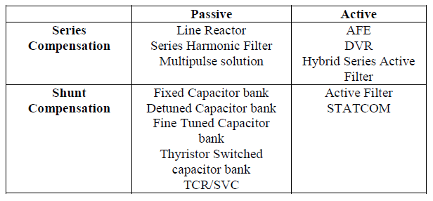
Some of the solutions mentioned in the table above are not ideally suited or intended for harmonic mitigation, they are mentioned for the sake of completeness.
The following types of compensation are mentioned for sake of completeness and will not be discussed further. A Thyristor Controlled Reactor (TCR), is a parallel device where thyristors are used with angle firing control to effectively vary the inductance value of a large reactor. TCRs are frequently used in Static VAR Compensator (SVC) solutions to obtain dynamic reactive power control, most often on medium voltage. A Dynamic Voltage Restorer (DVR) can be used to mitigate sags and dips and can in turn be implemented in several ways. A Static Synchronous Compensator (STATCOM) is a power electronics based Voltage Source Converter that is used as a more modern version of an SVC. In essence, a STATCOM is a parallel active filter.
IV. PASSIVE SOLUTIONS – SERIES
The following section describes and compares passive series mitigation solutions.
Line Reactor
A line reactor is a 3-phase series choke placed in front of the rectifier on the line side of a drive. The line reactor will cause a voltage drop as seen from the rectifier; due to being inductive, the series impedance and hence voltage drop is larger the higher the frequency. Typical inductance values are 2-5%. Lower values than 2% have a very limited impact on the harmonics.
Advantages:
• Low cost
• Significantly reduces current distortion
• Adds protection to the rectifier
Disadvantages:
• Impractical in large drives
• Will not meet harmonic regulation levels on its own
• Need to handle full current of load, not only compensation current
• Drops voltage as seen by the drive rectifier
Series Harmonic Filter
The series harmonic filter is designed to significantly reduce harmonics. In a sense it is a series choke with a few added components tuned to trap more of the harmonics. A typical series harmonics filter can be seen in the figure below;

Compared to the series choke a stronger harmonic rejection ratio is achieved, with higher losses and a more resonance prone filter network. However, the solution is non-flexible as drive load cannot be added to a given series line filter. As with all series solutions, the filter must be sized to handle the full load current, not only the harmonic current
Advantages:
• More effective compensation of harmonics than line-choke
• Significantly reduces current distortion
• Adds protection of rectifier
Disadvantages:
• May be overloaded
• Non-flexible
• May result in leading power factor
• Needs to handle the full current of load, not only the harmonics
• Impossible to control the inrush current
Passive Solutions – Multi-Pulse
A special case of the passive series solution is the multi-pulse transformer. Multi-pulse solutions entail using a multi-pulse, or multi-winding transformer with phase shift in the windings. Every secondary winding utilizes its own rectifier. A 12-pule solution uses two secondary windings and dual rectifiers. An 18-pulse solution adds one secondary windings and one rectifier. For example, an 18 pulse solution will look like this:

Note the phase shifting properties for each of the secondary windings. As discussed in the introduction, the formula ℎ=𝑝∗𝑘 ±1, where p is the pulse number and k is 0,1,2… shows the harmonics exhibited. For example, an ideal 18-pulse system will then only show harmonics of orders 17, 19 (k=1), 35, 37 (k=2) and so on. Harmonics of orders 5, 7, 11, 13, 23, 25 and so on are cancelled out. However this is only true in the ideal case where the multi-winding transformer is ideal and the feeding grid is without unbalance.
If the multi-pulse transformer itself is not perfectly balanced, the result will be the emission of harmonics outside the relation given above (ie: 13th harmonic in an 18-pulse system).
In the same vein, the multi-pulse system requires symmetrical loading on the secondary windings in order for the harmonic cancellation to occur.
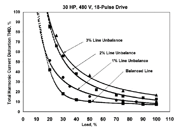
Multi-pulse systems are very sensitive to voltage unbalance. Consider a case with an 18-pulse drive under 50% load. When the unbalance is increased from 0% to 3%, the current THD increases from 10% to 35%. In a similar way, under 100% load, the current THD increases from 8% to 16%. The figure below [4] shows THD as a function of loading for a fixed set of voltage unbalances.
When compared to other solutions, the multi-winding transformer is physically large and heavy. In applications where space and weight is at a premium, this is a major drawback.
Advantages:
• More effective compensation of harmonics than a line-choke
• Significantly reduces current distortion
• Adds protection to the rectifier
Disadvantages:
• Sensitive to voltage unbalance
• Sensitive to transformer asymmetry
• Non-flexible
• Large and heavy (Physically large)
• Optimal cancellation only with symmetric drive loading
• Very hard to retro-fit
• Extended down-time when transformer failure occurs
V. PASSIVE SOLUTIONS – SHUNT
Passive shunt filters encompass a wide range of solutions. With regards to compensating reactive power, these are the most common type of solution. They can generally be divided into the following basic types:
• Fixed capacitor banks
• Contactor based units
• Detuned contactor based
• Thyristor based capacitor banks
• Fine-tuned passive filters
For brevity of discussion, some of the mentioned solutions will not be discussed as they cannot be used to mitigate harmonics. Instead the discussion will focus around the generic benefits and disadvantages to passive shunt solutions. In the figure below, a fixed fine-tuned filter, a contactor based detuned filter and a thyristor based fine-tuned filter can be seen from left to right.

As the shunt connection places the compensation in parallel with the load, the filter can be sized to fit the disturbance rather than the load. In the case of a fine-tuned 5th harmonic filter, this means that the filter will only be sized for the 5th harmonic rather than the total load size. A typical variable speed drive load will have a 5th harmonic current in the neighborhood of 25-30% of the fundamental load current. This means the shunt connected filter may be significantly smaller than the series filter. We will later show that this also holds true for active solutions.
As with all passive solutions, the loading cannot be controlled. The loading of the filter will be determined by the impedance of the filter, the connected grid and the loading on the grid. Further, several fine-tuned filters may interact when placed in the same grid. Since the tuning will depend on and interact with the source impedance, the end results of adding fine-tuned shunt filters are often unpredictable. Consider the following example from [3], where three fine-tuned filters (tuned to 5th, 7th, and 11th harmonic) are placed on a grid with varying source impedance (an oil rig). In the picture below we have one (case iii), two (case ii) and four generators running (case i). Note that the tuning does not move around very much; however the resonant peaks move around significantly, increasing the risk of interaction with other loads.

Advantages:
• More effective compensation of harmonics than a line-choke
• Possible to retrofit
Disadvantages:
• May be overloaded
• Non-flexible
• Sensitive to grid conditions
• Will interact with other passive loads
• Will interact with grid power quality
• Impact on voltage difficult to determine
• Grid interaction unpredictable and in many cases non-intuitive
VI. ACTIVE SOLUTIONS – SERIES
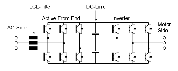
The active series solution is usually implemented in the form of an Active Front-End variable speed drive, or simply an AFE. In a regular variable speed drive, the rectifier is controlled via diodes. With an AFE these are replaced with an active (usually IGBT-based) controlled rectifier. In the figure below, the left part is the active rectifier, the DC energy storage is in the middle, and the inverter (motor) part is to the right. As can be immediately seen, the active rectifier needs to be able to transmit the full power of the load.
One of the immediate benefits of this scheme is the ability of the active rectifier to feed electrical energy back to the grid during braking. AFE drives usually have very low current distortion (typically down to 5% THD) and excellent power factor. The ability to feedback braking energy is very useful in some applications such as ski lifts and elevators; in other applications, AFEs are only installed for their low harmonic signature.
Some tradeoffs affect the AFE performance in particular. In order to make the AFE as light and compact as possible, it is desirable to lower the switching frequency of the active rectifier. This however puts stress on the line filter and creates a higher switch ripple. Increasing the switching frequency is however done at a very high cost; the active rectifier grows physically larger and becomes more expensive.
The voltage waveform below [5] clearly illustrates a severe case of ripple;
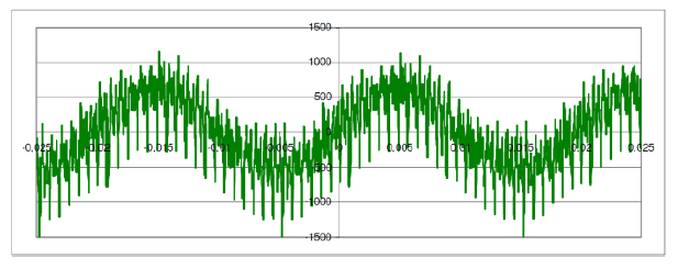
The ripple in the figure above is centered at the 50th harmonic with sidebands at 47th and 53rd; this will severely interact with other equipment on the same bus and may cause equipment malfunction, breaker nuisance tripping and other problems.
Due to the active rectifier, there is a voltage boost of the DC-voltage compared to a conventional 6-pulse drive with a Diode rectifier. The higher DC voltage creates a higher ripple on the motor side, meaning that a dV/dt filter may be needed, especially in an application with higher motor voltages (600-690VAC).
For AFE drives with LCL-filters, special concern must be taken with regards to the switching frequency and the resonance point of the line filter. Normally, the switch frequency is above the resonant frequency in order to benefit from the higher damping. However, this puts the AFE at a double disadvantage since the switching frequency already needs to be low in order to not make the active rectifier part too bulky and lossy. The below figure [8] illustrates the problem of having low damping in the LCL filter – a resonant peak is created which might interact with other loads in the grid. The only way of reducing the severity of the peak is to add damping. The other option would be to increase the switching frequency.

Due to being a series design – transmitting the full load current – the AFE needs to have a low switching frequency in order to not be too inefficient. The high current capacity in combination with a low switching frequency leads to large switching ripple and a higher risk of interacting with other loads on the grid, possibly causing harmonic resonances.
Unless the active frond end part is split from the inverter part in a common DC-bus arrangement, achieving redundancy of the front-end or compensation part is impossible.
Advantages:
• Very efficient suppression of harmonics
• Excellent power factor
• Able to feed energy back to grid
• Insensitive to network unbalance
Disadvantages:
• Active rectifier must transmit full load power
• Large, complex
• Harmonics compensation is tied to drive
• Switch ripple on grid side
• Higher switch ripple on motor side due to boost voltage
• High losses
• Expensive
• Difficult to retrofit
• Redundancy practically requires common DC-bus
• Combination of LCL filter and low switching frequency
• Grid interaction unpredictable and in many cases non-intuitive
VII. ACTIVE SOLUTIONS – SHUNT
An active filter is connected in shunt – in parallel – with the load and can be used to mitigate a number of power quality problems. The most common is the reduction of harmonics caused by variable frequency drives. The majority of active filters use IGBT technology. Active filters work by measuring the load current, analyzing the harmonics and then injecting counter-phase harmonics in order to cancel out the unwanted harmonics.

Since the shunt active filter only needs to handle the size of the disturbance (ie: the harmonics), which are a fraction of the amplitude of the full current, using a higher switching frequency and a higher resonance frequency in the LCL filter is feasible. This significantly lessens the risk of grid interaction and allows the shunt active filter to compensate higher harmonic orders.
Most commonly active filters work in global or selective mode. Global mode means that the active filter tries to cancel out all harmonics irrespective of order. This can be done by removing the fundamental frequency component from the measured signal. Selective mode means that the user is given the opportunity to configure which harmonics to compensate. During selective compensation, it is possible to target a particular issue. This may allow significant downsizing of the active filter. For example, in the case of the 11th harmonic triggering a resonance, an active shunt filter with selective compensation may be configured to only target the 11th harmonic, in turn significantly lowering the required current rating of the active filter.
It should be pointed out that the ability to downsize the active filter to only compensate the needed harmonics is a direct consequence of being a parallel device. An active filter is insensitive to network unbalance and the user may select to only partially compensate the load in order to reach a pre-determined set of criteria.
The active filters will introduce switch ripple, but much less than the equivalent AFE solution due to smaller size relative to the load and due to the higher switching frequency. In modern active filters, the switch ripple is kept under control.
Advantages:
• Most efficient compensation
• Simple to retro-fit
• Tunable to the problem at hand
• Compact
• Allows redundancy to be designed into the system (due to being separate from load)
• Smaller than series solution
• Losses lower than multi-pulse, AFE and series filters
• Simple to compensate groups of different load
• Cannot be overloaded
• Can provide VAR compensation
• Insensitive to network unbalance
• Significantly less switch ripple than AFE
Disadvantages:
• Introduces switch ripple
VIII. COMPARISON
Consider a case where a 1000A variable frequency drive is to be compensated. The resulting amount of harmonics to be mitigated is dependent upon the system impedance and the equivalent series reactance. In a weak grid, the current distortion might be as low as 20%. In a strong grid the number might be up to 38%. In absolute numbers this means a harmonic current of 200 – 380 A RMS.
In the case of harmonic mitigation, it will be enough to just attenuate the harmonics enough to reach a certain voltage distortion (for example 5% according to IEEE-519(1992) [6]). According to the same standard there will also be requirements on the TDD (Total Demand Distortion). In the worst case, the TDD will be required to be less than 5% under all conditions, meaning that if the 1000 A drive is the only system on the PCC (Point of Common Coupling), maximum emission of harmonic current is 5% of the demand current or 50 A RMS. In order to achieve the goal given in this example, the harmonic reduction in terms of current needs to be 150 – 330 A RMS. The actual numbers will vary with application, however the principle holds true in all cases.
The example is illustrated in the figure below.

The ability to downsize the solution to fit a particular purpose is one of the biggest general advantages of parallel compensation circuits compared to series circuits. As demonstrated by the example above, a series compensation would need to have a current rating of 1000 A RMS; the shunt compensation will be 150 – 330 A RMS even when compensating all harmonic orders. The difference will increase in the case where a more specific, pin-pointed solution is required.
IX. PERFORMANCE COMPARISON
In the following section performance is compared on a selection of parameters. The table below compares current compensation results and efficiency of a couple of solutions. Data is courtesy of Danfoss [7]. In the data below, no consideration is given to imperfections in the grid such as unbalance. As has been shown above, results may be far worse for some solutions under those circumstances.
Table 2. Current compensation results and efficiency of a couple of solutions

A. Case Study 1
In the following case, AFE drives are compared with the combination of 6-pulse drives and active shunt filters. Total installation size is 9.2MW with 8400 operating hours per year. Most of the time, 50% of the load is running. The specification requires a current harmonic distortion (ITHD) of less than 5%.
Table 3. AFE drives are compared with the combination of 6-pulse drives and active shunt filters

Note the very large difference in efficiency, footprint and energy losses. In this case, the losses are increased 116% compared to 6-pulse drives and active filters. The reduced losses in turn lead to a significantly reduced need of cooling and ventilation.
B. Case Study 2
In the following case, four harmonics mitigation solutions are compared; no compensation of 6-pulse drives for reference, 12-pulse, 18-pulse, AFE and Active Filters. The test case is a typical installation on a vessel, but the comparison is relevant for on-shore applications as well. In this case, the required distortion level is VTHD < 8%, and no single harmonic exceeding 5%, effectively being compliant with ABS, DNV/GL or IEC/EN 50160.
The vessel is equipped with 4 generators, each rated at 1125 kVA and X’’d of 18%. The vessel is further equipped with four thrusters – two main thrusters rated at 1600 kW each, and two bow thrusters at 600 kW each. Worst case from a harmonic standpoint is full steaming, all four generators online and both main thrusters running at 100%. In a full system study, other operating cases will be taken into consideration as well, but are left out from the results below for brevity.
During the simulation of the results presented here, all cases were taken into account and only the most severe was presented. In other operational modes, the total loading on the vessel grid will be lower.
Without compensation, total harmonic voltage distortion (VTHD) is simulated to between 14.5 – 18% depending on installed equivalent series inductance in the drives.
The table below shows the results in terms of compensation, as well as the size (in length) and weight of the different solutions. Active Filters are included twice; in the first case to just reach the requirement of the classification society (DNV/GL or ABS), and in the second case sized for full compensation.
Table 4. Results in terms of compensation

In the simulation above, no consideration is given to non-ideal components; with offset voltages in the multi-pulse solutions yield higher distortion values, which might be critical in the 18-pulse case. The example serves as a good indicator on how the overall system can be downsized and made more efficient with parallel compensation. Note that the comparison is made using air-cooled units only. For liquid cooled devices, the size/weight proportions stay roughly the same (drives and active filters become more compact – passive filters and transformers do not).
X. DISCUSSION AND SUMMARY
Harmonics is a major concern in many applications today. The increased use of variable frequency drives introduce more energy efficient systems but also an increased harmonic loading. In this paper a number of compensation techniques have been discussed in general terms. Generalized comparisons have been made as well as two case studies.
REFERENCES
[1] J. Persson, “How to Specify Harmonics”, Comsys AB, Lund, 2014
[2] D. J. Carnavole, “Applying Harmonic Solutions to Commercial and Industrial Power Systems”, Eaton | Cutler-Hammer, Moon Township, PA, 2003
[3] A. R. Dekka, A. R. Beig, M. Poshtan, ”Comparison of Passive and Active Power Filters in Oil Drilling Rigs”, The Petroleum Institute, Abu Dhabi, UAE, 2011
[4] K. Hink, “18-Pulse Drives and Voltage Unbalance”, MTE Corporation, Menomonee Falls, WI, 2002
[5] L. Moran, J. Espinoza, M. Ortiz, J. Rodrique, J. Dixon, “Practical Problems Associated with the Operation of ASDs Based on Active Front End Converters in Power Distribution Systems”, Industrial Applications Conference, 2004, Vol. 4, 3-7 Oct. 2004, pp 2568-2572
[6] IEEE Std 519-1992, “IEEE Recommended Practices and Requirements for Harmonic Control in Electrical Power Systems”, IEEE, New York, 1993
[7] Danfoss, “Harmonic Mitigation – Requirements and Danfoss Drives’ solutions”, Danfoss A/S, Gråsten, 2009
[8] A. Julean, “Active Damping of LCL Filter Resonance in Grid Connected Applications”, Master Thesis, Aalborg Universitet, Aalborg, 2009
Source URL: https://comsys.se/our-adf-technology/comparing-harmonics-mitigation-techniques/
