Published by Henryk KOCOT1, Agnieszka DZIENDZIEL1,2, Silesian University of Technology, Institute of Power Engineering and Control Systems (1), PSE Innovations (2)
Abstract. The paper discusses aspects related to the modeling of multi-circuit overhead power lines (HV, EHV), in particular their zero models. The article presents a mathematical model of two-voltage three-circuit overhead line in power system’s structure which includes the impact of lightning conductors, occurrence of bundle conductors and occurrence of differentiation in rated voltage levels of circuits of an overhead line. Moreover, the influence of the lack of symmetrization in such line on the voltages symmetry was examined.
Streszczenie. W artykule omówiono aspekty dotyczące modelowania wielotorowych linii napowietrznych wysokich i najwyższych napięć, a w szczególności ich modeli zerowych. Zaprezentowano model matematyczny, który stanowi opis dwunapięciowej trójtorowej linii napowietrznej w strukturze systemu elektroenergetycznego (SEE), uwzględniający oddziaływanie przewodów odgromowych, występowanie przewodów wiązkowych oraz zróżnicowanie poziomów napięć znamionowych torów prądowych linii. Dokonano również oceny wpływu braku symetryzacji linii na symetrię napięć w takiej linii. (Modele impedancyjne wielotorowych wielonapięciowych elektroenergetycznych linii napowietrznych).
Keywords: multi-circuit overhead lines, earth-return circuits, voltage asymmetry, zero model of power line.
Słowa kluczowe: wielotorowe linie napowietrzne, obwody ziemnopowrotne, niesymetria napięć, model zerowy linii napowietrznej.
Introduction
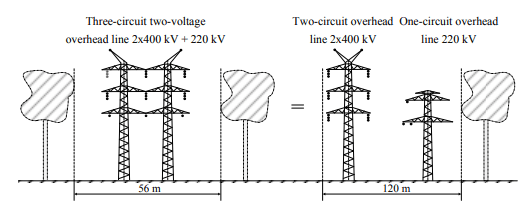
This year, 25th of January 2019, the record peak power demand 26,504 MW in the Polish power system occurred. The previous maximum power demand, which amounted 26,448 MW [1], was noted 28th of February 2018. The growing up demand for electric power extorts growth of generation sources and also lines and structures of the transmission system. Overhead power lines are the biggest and most extensive element of the transmission system fulfilling one of basic and the most important roles of any power system: they make possible electric energy transmission for the big distance. To find a territory for power network enlargement is the most difficult task. That suggests use multi-circuit lines. An additional advantage of this solution is enlargement of the transmitted power in the given section because of bigger number of circuits. The multi-circuit multi-voltage power lines in which at least two circuits placed on the common structure, have different voltage rating are also an interesting solution. Such an approach allows considerably reduce a width of the technological band, what illustrates the Fig. 1.
Multi-circuit multi-voltage overhead power lines have many advantages which cause, that their significant increase as well in Poland as in the world is observed.
An appearance of new elements of the subtransmission networks, i.e. multi-circuit and multi-voltage overhead power lines, carry with it necessity of their appropriate description using a mathematical model. The appropriately made mathematical model with defined and determined parameters takes into consideration all substantial features, phenomena and interactions occurring during operation of the object. In the paper as a mathematical model are understood admittance matrices of symmetrical components, which describe properties of the overhead line, where values of the admittance matrices are made dependent on earth-return circuits’ parameters, determined from geometry and material constants of circuits. In the paper attention was devoted mainly to zero model of overhead power line. An admittance model of the two-circuit single-voltage overhead line is well-known, therefore relationships which allow to determine a three-circuit multi-voltage line considering appearance of overhead earth wires and bundle conductors, are worked out and presented within the frames of the paper.
A computational model of the overhead line – earth-return circuits
Creation of overhead lines’ mathematical models is based on the earth-return circuits’ theory. An earth-return loop was schematically shown on the Fig. 2.
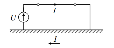
In earth-return circuits the earth treated as a homogeneous semiconducting space is a return conductor; phase conductors and earth wires are treated as parallel running closed earth-return loops. In this part of the paper the term of impedance of conductors which appears in earth-return circuits was discussed in order to understand an origin of particular components in final relationships.
The earth-return circuits are described by impedances: own W and mutual M. The own impedance is connected with an appearance of electromagnetic field penetrating inside of the conductor and also with inducing of electric rotational field around the discussed conductor because of current flow.
An own specific impedance of a single conductor amounts (in Ω/km) for frequency 50 Hz [3]:
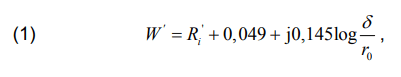
where Ri’ – own specific resistance of the conductor (in Ω/km), δ – distance of the discussed overhead conductor from the fictitious equivalent conductor placed in the earth (in m), r0 – characteristic radius of a single conductor (in m).
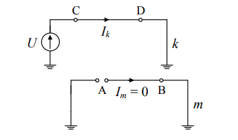
A mutual impedance is connected with influence of different conductor(-s) on the discussed overhead conductor. This mutual impedance is defined as a quotient of the potential difference in the section AB of the conductor and the current Ik (Fig. 3).
A mutual specific impedance for frequency 50 Hz amounts [3]:
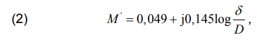
where: D – geometrical distance between the discussed conductors k and m.
Zero model of a two-circuit overhead line
In course of considerations the following assumptions with relation to the system have been made [4]:
– the line is a linear element and appearing in it voltages and currents are mutually linear combinations,
– the line conductors create with the earth earth-return circuits,
– the line has a phase symmetry,
– the line is symmetrical with regard to its ends,
– capacities and leakages were passed over.
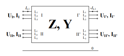
In order to obtain a mathematical model the line was treated as a multi-gate element where number of terminals is equal the number external nodes of the line. For two-circuit line after creation of the reference node, what means transfer its impedance to the phase conductors, it is obtained the scheme as in Fig. 4, being the twelve-node circuit [4].
A basic dependence between values of currents and nodal voltages is given by the relation (3):
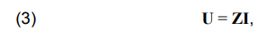
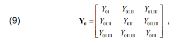
and the matrix of coefficients Z has a degree 12×12 in the case of two-circuit line. An adequate ordering the own and mutual line impedances, taking into consideration assumptions of symmetry, and passage to symmetrical components results obtaining only admittance matrix of positive components Y1 and negative Y2, which are the diagonal matrices, and also null matrix Y0 (the mutual matrices between particular components do not appear). The matrix Y0 has form:
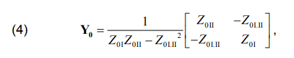
or taking into consideration the adequate own and mutual impedances:
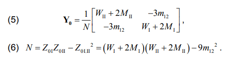
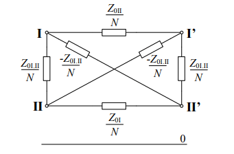
The matrix Y0 is represented by a zero scheme of the two-circuit line (Fig. 5) named an envelope scheme [5].
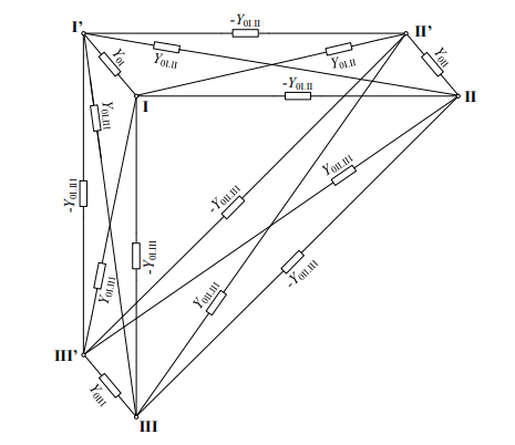
A mathematical model of the three-circuit overhead line
As result of the taken assumptions the analogous deliberations for the three-circuit line presented as an eighteen-node circuit lead to obtaining the admittance matrix of the zero-sequence component Y0 described by the relation (7):
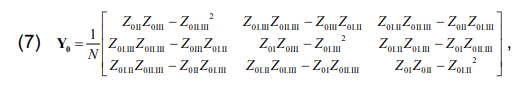
and

The admittance zero matrix Y0 takes the form:
and the adequate scheme is shown in the Fig. 6:
A zero model of the real three-circuit two-voltage overhead line
The obtained mathematical model was used to describe the real two-voltage three-circuit overhead line operating in the area of the PSE-South, located nearby the Łagisza station. The analysed is a type of EHV+EHV (2×400 kV + 220 kV) length 4,81 km, with a horizontal phase conductor configuration. Phase conductors for 400 kV circuits are a type of AFL-8 3×350 mm2 , for 220 kV circuit are of type AFL-8 525 mm2 , and earth wires AFL-1,7 95 mm2 .
A silhouette and geometrical parameters of tension supports of the deliberated three-circuit line are shown in the Fig. 7.
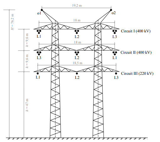
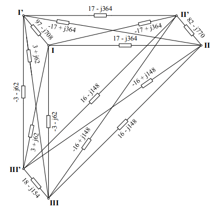
Thanks to a knowledge of the geometrical and material parameters the equivalent zero scheme was determined and shown in the Fig. 8. In calculations it was taken into account the influence of the earth wires by including their own and mutual impedances to the impedances of the phase conductors (a way of this including is given (among others) in [4], [7]). An appearance of the bundle conductors was also taken into consideration their aggregation to one equivalent conductor. Because of differentiated levels of rated voltages of circuits the line parameters were given per-unit and as a reference power was taken value of 100 MV·A. As reference voltages were taken rated voltages of particular circuits of the line.
An impedance asymmetry of the real line
The real line is usually not symmetrized (concerning the impedances) by transposition of phase conductors. It is caused by a big number of the necessary transpositions (full symmetrization of the three-circuit line needs 27 transpositions) and first of all by technical difficulties in carrying out the full transposition in the line.
In order to estimate an impedance asymmetry of the line a model without symmetrization was determined. A distinctive feature of the model is appearance of mutual impedances for symmetrical components between each pair, that means an appearance of voltages of all components at the current flow of only one component in the line (i.e. a symmetrical current).
An influence of the impedance asymmetry of the analyzed line was determined by calculating voltages at the end of the line supplied with the symmetrical voltage of the positive sequence and charged with the current of the only positive sequence component. As a measure of the voltage asymmetry was taken a voltage asymmetry index α2% defined as a quotient of a value of a negative component of voltage and a value of a positive component and also unbalance index α0% defined as a value of a zero component of voltage to a positive component. Results for two different loads are presented in the table 1.
Table 1. Indices of asymmetry and unbalance of voltages in the three-circuit line with no transposition for different loads

The presented in the table 1 results show, that an impedance asymmetry of the line with no transpositions is not significant, because even at the full admissible load in all circuits (what does not happen in practice) maximal index amounts 0,33%. The similar results were presented in [8] for the two-circuit line. But it must be noticed that the analyzed section of the three-circuit two-voltages line is very short (4,81 km). In the case of longer lines the asymmetry indices can reach a boundary values which are given in operational and exploitation directions of particular networks. In the discussed case, at the predetermined construction of the tower and the used conductors, for the line length equal 25 km value of the asymmetry index reaches 2%.
Another way of estimation of influence of lack of transpositions is analysis of values of own impedance matrices for symmetrical components. Because transformation of the phase impedance matrix into the symmetrical components matrix is aimed to diagonalize the impedance matrix (what takes place in case of symmetrical phase impedance matrix) therefore from attributes of own values results that values of particular symmetrical components are equal the own values of this matrix. In case of lack of symmetrization of the phase matrix its own values are different. In the analyzed case the maximum relative error in the module of differences between the own values determined for the case with the phase transposition and without it amounts about 10% what means, that differences in particular impedances can be quite significant, what in turn can influence values of fault impedances calculated in such schemes [9].
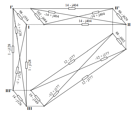
A full zero model of the line and the simplified zero model
On account of a big complexity of a zero model the simplified model compound from three separate envelope models for each pair of circuits of the line, i.e. I with II, II with III and I with III. This simplified model being a connection of three individual envelope models was presented on the Fig. 9.
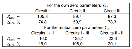
In order to compare the both models the percentage relative errors were determined after relations (10) and (11):
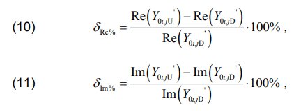
where: δRe% – the percentage relative error for the real part (in %); δIm% – the percentage relative error for the imaginary part (in %); index U means parameter of the simplified model, index D – of the exact model i, j – numbers of circuits; i, j ∈ {I, II, III}
The table 2 includes values of the relative error resulting from use of the simplified model. The simplified model significantly differs from the exact model, as for own as for mutual parameters. Errors in determination of particular parameters can exceed 100%. It means that the simplified model can not be applied as an substitute of the exact model.
Table 2. Relative percentage errors resulting from application of the simplified model [6]
Summary
A continuous development of the multi-circuit multi-voltage overhead line results in necessity of their adequate description. The determined nodal admittances of the three-circuit multi-voltage overhead line expresses structure and parameters of this element of the network, therefore allows to describe it precisely in the power system’s structure. Thanks to this the mathematical model can be used for representation of steady states without significant phase asymmetries or quasi-steady states at simplified short-circuit calculations.
An analysis of the lack of transpositions (i.e. symmetrization of the line) by determination of asymmetry and unbalancing indices for only the positive component of the load current showed that even big values of the current do not cause the significant voltage asymmetry. Nevertheless taking into consideration a development of the analyzed lines and perspectives of growth of their length, it can be expected an increase of the discussed asymmetries.
It seems to be necessary to continue analyses of importance of the impedance asymmetry in the multi-circuit overhead lines all the more that their constructional solutions are significantly differentiated. The investigated real three-circuit two-voltage line has relatively low geometrical asymmetry. Other solutions, presented e.g. in [2] are more asymmetric.
The carried on deliberations on possibility of creation of the simplified zero model showed, that the model compiled from three independent envelope models for each pair of the three circuits of an overhead line is characterized by significant errors (tabl. 2). This means that phenomena and couplings which take place during operation of the overhead line were not sufficiently taken into consideration. The simplified model takes into consideration only the “direct” impacts: circuit I for the circuit II, circuit II for the circuit III etc., but omits the “indirect” influences, i.e. e.g. circuit I for the circuit II through the circuit III. The obtained results testify that it is a significant circumstance and considerably influence the obtained values of parameters of the model. As result the simplified model does not fully renders properties of the overhead line and can not be an alternative for the exact model.
REFERENCES
[1] Strona internetowa Polskich Sieci Elektroenergetycznych S.A. http://www.pse.pl
[2] Kumala R., Identyfikacja zakłóceń w wielotorowych różnopoziomowych napięciowo liniach elektroenergetycznych, Rozprawa doktorska, Gliwice 2016
[3] Kosztaluk F., Flisowski Z., Metody analizy układów przewódziemia, Przegląd Elektrotechniczny, 10/2001
[4] Bernas S., Ciok Z., Modele matematyczne elementów systemu elektroenergetycznego, Wydawnictwo Naukowo-Techniczne, Warszawa 1977
[5] Kacejko P., Machowski J., Zwarcia w systemach elektroenergetycznych, Wydawnictwo Naukowo-Techniczne, Warszawa 2013
[6] Dziendziel A., Wielonapięciowe elektroenergetyczne linie napowietrzne, Praca dyplomowa magisterska, Gliwice 2018
[7] Żmuda K., Elektroenergetyczne układy przesyłowe i rozdzielcze. Wybrane zagadnienia z przykładami, Wydawnictwo Politechniki Śląskiej, Gliwice 2014
[8] Robak S., Pawlicki A., Pawlicki B., Asymetria napięć i prądów w elektroenergetycznych układach przesyłowych, Przegląd Elektrotechniczny, 07/2014
[9] Miller P., Wancerz M., Wypływ sposobu wyznaczania parametrów linii 110 kV na dokładność obliczeń sieciowych, Przegląd Elektrotechniczny, 04/2014
Authors: dr hab. inż. Henryk Kocot, prof. PŚ, Politechnika Śląska, Instytut Elektroenergetyki i Sterowania Układów, ul. Krzywoustego 2, 44-100 Gliwice, E-mail: Henryk.Kocot@polsl.pl;. mgr inż. Agnieszka Dziendziel, doktorantka w Politechnice Śląskiej, Instytut Elektroenergetyki i Sterowania Układów, ul. Krzywoustego 2, 44- 100 Gliwice, E-mail: Agnieszka.Dziendziel@polsl.pl
Source & Publisher Item Identifier: PRZEGLĄD ELEKTROTECHNICZNY, ISSN 0033-2097, R. 95 NR 12/2019. doi:10.15199/48.2019.12.58
