Published by Mohamed M. EL-Shafhy1, Alaa M. Abdel-hamed1, Ebrahim A. Badran2,
Electrical Power & Machines Department, High Institute of Engineering, El-Shorouk Academy, Cairo, Egypt (1), Electrical Engineering Department, Faculty of Engineering, Mansoura University, Mansoura, Egypt (2)
Abstract. Recently, there are increasing interest in studying the ferroresonance phenomenon, due to the various problems it causes to power quality and the destruction of network parts, insulators and consumer devices. As the ferroresonance leads to a significant increase in voltage or/and current with harmonic presence, both of which represent a threat to the stability of the electrical network and its parts. The influence of ferroresonance on the distribution system is crucial because the distribution system is the network’s closest part to the consumer, and any effect it has will have an impact on the customer. This paper presents a state of the art of ferroresonance problem. The most visible signals for ferroresonance and analytical methods used to indicate its occurrence are presented. The investigation of ferroresonance in the radial distribution system and the effect of integrating Distributed Generation (DG) into the distribution zone on this phenomenon are presented. The latest methods used to mitigate and prevent ferroresonance are discussed. Furthermore a technique for suppressing ferroresonance is implemented. The ferroresonance in power transformer and the effect of load variation on it will be presented. PSCAD/EMTDC software is used to simulate the study.
Streszczenie. Ostatnio obserwuje się coraz większe zainteresowanie badaniem zjawiska ferrorezonansu, ze względu na różne problemy, jakie powoduje w zakresie jakości zasilania oraz niszczenia elementów sieci, izolatorów i urządzeń konsumenckich. Ponieważ ferrorezonans prowadzi do znacznego wzrostu napięcia lub/i prądu z obecnością harmonicznych, które to oba stanowią zagrożenie dla stabilności sieci elektrycznej i jej części. Wpływ ferrorezonansu na system dystrybucyjny jest kluczowy, ponieważ system dystrybucyjny jest częścią sieci najbliższą konsumentowi, a każdy jego wpływ będzie miał wpływ na klienta. Artykuł przedstawia aktualny stan wiedzy na temat ferrorezonansu. Przedstawiono najbardziej widoczne sygnały dla ferrorezonansu oraz metody analityczne służące do wskazania jego występowania. Przedstawiono badania ferrorezonansu w promieniowym układzie dystrybucyjnym oraz wpływ integracji Generacji Rozproszonej (DG) w strefę dystrybucji na to zjawisko. Omówiono najnowsze metody stosowane do łagodzenia i zapobiegania ferrorezonansowi. Ponadto wdrażana jest technika tłumienia ferrorezonansu. Przedstawiony zostanie ferrorezonans w transformatorze mocy i wpływ na niego zmian obciążenia. Do symulacji badania stosuje się oprogramowanie PSCAD/EMTDC. (Ferrorezonans w sieciach rozdzielczych – stan wiedzy)
Keywords: Ferroresonance, DG, Distributed Generation, PSCAD.
Słowa kluczowe: Ferrorezonans, DG, Generacja Rozproszona, PSCAD.
Introductions
The goal of designing the power system is to deliver electrical power with lowest costs, low pollutant emissions level, maximum efficiency, and high power quality [1]. With the great technological advances these days, devices connected to the electrical grid are becoming more sensitive to system disturbances and transients phenomena such as all events due to switching actions, energizing and de-energizing elements of the power system and faults [2].
The power system does not always work in a steady-state condition, but it may go via transient states. Despite the short time of transient cases compared to the steady-state conditions of the system, they cause problems such as high voltage or current, poor power quality, drop in voltage or frequency and some harmful phenomena like ferroresonance effect [3]. Hence the interest of researchers are increased to solve these problems to provide the power to the consumer with the appropriate quality. Researchers are working to reduce the problems related to ferroresonance phenomena especially with the increase in nonlinear element in power system [4]. Problems related to transient can be classified into two categories: first impulsive and second oscillatory [5].
Ferroresonance is oscillatory phenomenon threatening the stability of the electrical network [6][7]. Also, ferroresonance refers to voltage displacement or natural instability [8]. It can cause damage to system equipment, insulation and consumer’s distribution devices. Also, it results in misoperation of protection devices due to overvoltage and/or overcurrent of peak value that can exceed more than twice of the normal value [9]–[16]. These phenomenon are caused by abnormal operations results in thermal and electrical stresses [17],[18], [19]. Researchers classified the ferroresonance phenomenon as low frequency electromagnetic transients of frequency ranges from 0.1 Hz to 1 kHz [4], [20]–[22]. This nonlinear phenomena can be blamed for several unexplainable breakdowns [23].
Recently, the phenomenon of ferroresonance has increased significantly in the electrical network. This phenomenon appears in all parts of the electrical network and different voltage levels [19]. Ferroresonance appeared in the protection system elements like Current Transformer (CT) and Potential Transformer (PT). The occurrence of ferroresonance in PT was discussed in [24] and recommendations to avoid the investigation of ferromagnetic resonance were provided. Ref. [25] presented an investigation of the ferroresonance in PT and based on the self-excitation characteristic. PT’s self-excitation characteristic was used to identify ferroresonance. Ref. [26] examined the effects of switching transients and its contribution to the resultant ferroresonance at the coupling Capacitor Voltage Transformer (CVT). Ref. [27] discussed the ferroresonance in PT and infer it through vibration analysis. Ref. [28] explained the extent of the damage caused by the ferroresonance phenomenon on the CVT and proposed a suppression circuit. The occurrence of ferroresonance in PTs during the system energization event was discussed in Ref. [29]. In Ref. [30], the faults in Medium Voltage (MV) network and its role in ferroresonance investigation at Voltage Transformer (VT) were discussed. Ref. [19] presented the occurrence of ferroresonance at the PT terminal on High Voltage (HV) GIS substation. In addition, many studies have shown the occurrence of ferroresonance in PT in different parts of the network, and many solutions and inhibitor circuits have also been presented in Refs. [5], [11], [13], [31]–[35].
In addition, many researchers discussed ferroresonance investigation in the power transformers. Ref. [36] presented the investigation of ferroresonance in power transformer caused by unhealthy switching and introduced its mitigation circuit. Ref. [37] discussed the asymmetrical phases deenergization of the wind farm its role in ferroresonance activation. Ref. [38] presented the prevalence of ferroresonance in the Montazer Qaem 63 kV substation. Ref. [39] provided the initiated of ferroresonance in unloaded power transformer terminated by cable. Ref. [40] explained the effect of power transformer energization in a 400 kV transmission grid on ferroresonance investigation. Ref. [41] dealt with the effect of the variation of Petersen coil on ferroresonance response in a power transformer. Salman in [42] studied the effect of the transmission line outage on ferroresonance response in power transformer. Ref. [18] provided an analytical method to detect the ferroresonance phenomenon in (MV) Networks. In addition, there are many researches in the form of an analysis and a case study only, without presenting actual studies like Refs. [24]- [14].
Ferroresonance also appears in the Distribution System (DS). It’s considered as a critical case because of closeness to loads. Ref. [53] examined the effect of changing the type of distribution transformer on the ferroresonance response, but this study was conducted in a no-load condition. Ref. [54] showed two ferroresonance states investigated in the distribution transformer, but both states were performed when the system was not loaded. Ref. [55] studied the effect of cable length and five legs three-phase distribution transformer on the ferroresonance response. Ref. [56] presented the ferroresonance condition in an underground DS resulting from unhealthy switching cases. Ref. [57] presented three ferroresonance cases in DS integrated with a PV system resulting from the break into interconnection between PV system and the transformer. Ref. [58] presented the occurrence of ferroresonance in DS. It presented the DS in an equivalent circuit without studying a real network.
From the previously presented studies, it is found that the phenomenon of ferroresonance is widespread in all parts of the power system, and a lot of research has been directed to this study. But most of studies dealt with this phenomenon in the form of simple cases or an analytical study only, although this phenomenon is affected by the slightest change in the system. A lot of research that investigated this phenomenon was in protection element parts such as PT and CVT. Others were interested in studying this phenomenon on the power transformer with high and medium voltages. However, the interest in studying this phenomenon in the DS falls short of expectations. Although the DS is the most affected area with loads and any change in these loads can change the network topology and may cause the system to rush into ferroresonance. With the current increase in the use of Distributed Generation (DG) in DSs, its effects on ferroresonance (according to the author’s knowledge) have not been highlighted.
Many studies presented the implementation of DG into DS but, its effect on transit states and ferroresonance investigation still are considered as a research gap. Therefore, this paper focuses on studying the phenomenon of ferroresonance in DSs and the effect of DG penetration on this phenomenon.
This article explains the different factors which caused by the occurrence of ferroresonance and the problems of ferroresonance. The paper provides the physical and analytical methods used to recognize ferroresonance in a network. The different shapes of ferroresonance modes are also explained. Furthermore, the modeling of ferroresonance’s equivalent circuit and transformer response at abnormal switching are provided. The change in transformer response is also displayed as the load varies. The effect of load variation on the radial power system response is studied. The effect of DG implementation on ferroresonance response is presented. Finally, a comparison between methods of mitigating and preventing the ferroresonance is presented. PSCAD/EMTDC software is used in this study.
The rest of the paper is organized as follow. Section II presents ferroresonance phenomena, its definition, the reasons for the occurrence of ferroresonance and ferroresonance problems. Section III presents simulation cases. Section IV presents radial system penetrated with DG as case study. Section V provides the latest mitigation methods of ferroresonance and introduces the implementation of the series ferroresonance suppression circuit. The conclusion of the paper is given in Section IV.
Ferroresonance background
Ferroresonance phenomenon
Ferroresonance means resonance occurred between parameters of the electrical network with element containing ferromagnetic material like a transformer or an inductor [1], [53], [56], [59], [60]. Ferroresonance considered as a special case of resonance [39], [57]. Ferroresonance is unpredictable phenomenon arises due to the interaction between system capacitance and non-linear inductance [45], [61]–[65]. Ferroresonance is a rare non-linear phenomenon in which energy fluctuates between a capacitive element and non-linear inductive element which alternatively becomes saturated. This phenomena causes the system to jump from a stable state to a stationary ferroresonant state [64]. It is still disconcerting phenomena until today [67]. This phenomenon can occur with small changes in the parameters of the network so, it is difficult to be predicted [68], [69]. Investigating ferroresonance is a difficult endeavor, owing to the large number of factors that might influence the phenomenon’s occurrence, as well as the phenomenon’s great sensitivity to very minor changes in power grid parameters [40].
The first to point to this phenomenon is Joseph Bethenod in 1907. He indicated a resonance in the transformer due to non-linear inductance but Paul Boutherot named this phenomena as ferroresonance in 1920 [56], [70]. Ferroresonance differs from normal resonance, or as some researchers call it, linear resonance. Normal resonance is an expected phenomenon that results from an interaction between capacitance and inductance, unlike ferroresonance, which is an unpredictable phenomenon that results from the interaction of capacitance with nonlinear inductance. Table 1 presents a comparison between ferroresonance and linear resonance [1], [53], [57], [71].
Also, Fig. 1 shows the difference between the equivalent resonant and ferroresonance circuits. The ferroresonance circuit incorporate ferromagnetic material resulting in the phenomenon of non-linearity [1], [72]–[76].
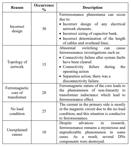
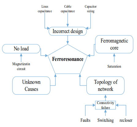
Ferroresonance phenomena can occur in all parts of the electrical network and at any level of voltage [72]. There are many causes that lead to ferroresonance effect. The most important reasons are due to incorrect design, topology of network, the ferromagnetic core of transformer and unexplained causes. Table 2 explains these reasons, their percent and their description [48], [77], [78]. These causes are summarized in the illustrated diagram shown in Fig. 2 [40], [48], [51], [79], [80]. Recently, researchers have demonstrated the role of the transformer tank in increasing the ferroresonance effect [81].
Table 1. Comparison between ferroresonance and linear ferroresonance

Table 2. Main reasons lead to ferroresonance

Ferroresonance Problems
The ferroresonance phenomenon is always accompanied by dangerous problems to power system network. These problems pose a major threat to the continuity and integrity of the power system which represented in the following:
Overvoltage
A ferroresonance in the DS causes a dangerous increase in voltage up to several times the rated value [82]. It is always followed by the occurrence of many other problems in the system such as insulators break down and failure in power system devices which may lead to cut off electrical service [70], [83]–[85].
The problem was displayed in many studies. Ref. [86] introduced the investigation of ferroresonance in an islanding mode of micro grid. The voltage was raised to 8 pu. Ref. [26] introduced the increase of voltage value to 2.5 pu in CCTV. Refs. [87], [41] introduced the increase of voltage value in power transformer to 5 pu and 3 pu as a case study. Ref [88] presented the investigation of overvoltage to 3 pu in VT as an analytical study.
Overcurrent
One of the problems that follows the phenomenon of ferroresonance is the occurrence of a significant increase in current. An increase in the current results in problems such as overheating in parts of the electrical system which lead to damage in system elements and insulators [34], [50].
In [89], the current value in the grid increased to 6 pu. Ref. [90] introduced the increase of current value to 2.5 pu in power transformer. Ref. [21] presented the results of an investigation of overcurrent up to 2 pu into a real system in Slovakia. Ref. [91] introduced the increase of current value to 5.5 pu in VT.
Power distortion
Ferroresonance causes a distortion of the electrical power wave, which results in the occurrence of harmonic problems [82]. These represent a major problem for electronics and sensitive devices. [67], [92]. Fig. 3 explains many shapes of power wave distortion.
Several studies revealed the issue. The distortion in the voltage wave caused by abnormal switching in a PV project connected to the grid was presented in ref. [59]. Refs. [34] and [93] introduced the distortion in VT voltage wave. Ref. [41] provided a case study of a power transformer in ferroresonance and the distortion of its voltage wave.
Saturation for devices containing ferromagnetic material
The fundamental cause of ferroresonance is the nonlinear ferromagnetic characteristics [19]. Ferroresonance causes a saturation of the elements containing ferromagnetic material [94], [95]. High current flow is resulted in saturation, which results in increased heat and irregular vibration of device components [52], [48].
Ref. [96] investigated the role of ferroresonance in transformer saturation. In [65], an analytical study was presented to eliminate saturation that may be caused by ferroresonance with ferromagnetic material. As a case study, Ref. [82] demonstrated the saturation of a nonlinear reactor due to ferroresonance. In [97], an analytical study of a single-phase transformer and the role of ferroresonance in iron core saturation was presented.
Misopertion of protection devices
Significant distortion of the power wave may results in protective device misoperation [98]. The occurrence of ferroresonance results in adverse effects on the voltage transformer, current transformers and measuring apparatuses. All these effects will lead to a defect in the operation of the protection system [25], [26], [30], [67]. Ref. [16] presented the failure of an overcurrent relay (OCR) in the Manitoba grid due to ferroresonance. Ref. [99] introduced challenge to the operation of OCR in DN due to ferroresonance.
Other problems
There are also some other problems that result from the occurrence of ferroresonance, such as the occurrence of abnormal noise, power flickers and damage to some power lines [27], [100], [89]. Ref. [12] presented many problems give rise from ferroresonance such as noise, flicker, damage to electrical equipment and overheating. Despite the complexity of this phenomenon, researchers have tended more recently to find solutions and ways to reduce this phenomenon for protecting the electrical network, its operators and customer devices connected to the network.
Ferroresonance modes and signs
Due to the phenomenon of nonlinearity of the ferroresonance circuit, it has a lot of responses [101]. These responses can be classified into four modes. These modes are known as fundamental mode, sub-harmonic mode, quasi-periodic mode, and chaotic mode [26], [44], [49], [102], [103].
Fundamental Mode
In this mode the current and the voltage have the same period (T) of the system called a period-1 (f0/1 Hz) with the same frequency but contain odd harmonics (3rd, 5th, 7th ,……, nth). It is small in comparison with fundamental component. Fig. 3a shows a Fundamental Ferroresonance (FF) waveform and its frequency spectrum [1], [34], [57], [62], [104].
Sub-Harmonic Mode
In this type, the signals of current and voltage have period multiples of the source period (nT) called a period-n (f0/n Hz) contains fundamental component with (nth) subharmonic. Fig 3b shows a Sub-Harmonic Ferroresonance (SHF) waveform and its frequency spectrum [1], [34], [57], [62], [104].
Quasi-Periodic Mode
This mode is called quasi-periodic mode or subperiodical mode. The signal of current and voltage is not periodic which has non-continuous frequency spectrum. The frequency is represented by equation nf1 + mf2, where f1/f2 are irrational real numbers, and n and m are integers. Fig. 3c shows a quasi-periodic ferroresonance (QF) waveform and its frequency spectrum [1], [34], [57], [62], [104].

Chaotic Mode
In this mode, the signal of current and voltage is not periodic which has continuous frequency spectrum and any frequency is not cancelled. Fig. 3d shows a Chaotic Ferroresonance (CF) waveform and its frequency [1], [34], [57], [62], [97], [104].
The shape of the system’s response to ferroresonance depends on the parameters of the system and also on the iron core material used with the inductor [44], [105]. Due to the extreme sensitivity of ferroresonance phenomenon, any change in system parameters, at ferroresonance condition, can lead to change in the system behavior [106].
There are several ferroresonance modes as Fig. 3 indicates [48]. Some modes lead to very high voltages and others modes may lead to voltages near nominal values. Therefore, it is important to identify the signs by which this phenomenon could be recognized. It is represented in physical phenomena such as overheat, noise, flicker, surge arrester failure and vibration at power system. When the aforementioned problems appear larger than the allowable limits, it can be a sign of ferroresonance in the system. Table 3 explains these problems and description [48], [53].
In addition the physical signs to identify the presence of ferroresonance are included in Table 3. Also, this phenomena can be recognized through analytical methods such as: Wavelet transform [2], [94], Analysis of the variables in the energy quality factors [38], Short Time Fourier Transform [38], Poincaré maps [92], Bifurcation diagram [95], and Phase plane diagram [38].
Table 3. Summary ferroresonance signs

Case study of ferroresonance
To illustrate the ferroresonance phenomenon, case studies are discussed in following subsections. The case studies will focus on ferroresonance in DSs. PSCAD/EMTDC software is used in the study.
Case 1: A capacitor in series with a saturable reactor
The circuit illustrated in Fig. 4a is the equivalent circuit for the ferroresonance phenomenon. The series connection of a capacitance with a saturable reactor and a single phase AC source lead to ferroresonance effect. It is clear that, the voltage has risen considerably beyond the rated value (11 kV) as presented in Fig. 4b. It can be seen the occurrence of quasi-periodic ferroresonance in which the voltage level rises to 3 pu as evidenced.

Case 2: A linear inductor with shunt and series capacitors
In this case, the simulation of the circuit is presented in Fig. 5a which consists of linear inductor with shunt capacitor, series capacitor, and 11 kV single phase AC source. Also, the same circuit is implemented in three phase form. It produces a quasi-periodic ferroresonance, as illustrated in Figs. 5a and 5b, with voltages of 3 pu in one phase circuit and 6 pu in three phase circuit.

Case 3: Abnormal switching of a transformer
In this case, the effect of load variation with abnormal switching of the transformer terminals and its role on ferroresonance occurrence are studied. This study is carried out in four stages: no-load transformer, transformer loaded less than 10%, transformer loaded with 10%, and transformer loaded with more than 10%.
The nature of the load on the terminals of the transformer and the abnormal conditions exposed to them control the shape of the transformer response [95],[111]. Therefore, an abnormal condition like abnormal switching effect on the transformer given at Fig. 6 will studied. This figure presents a 50 MVA, 230/11 kV Unified Magnetic Equivalent Circuit (UMEC) transformer that terminated with load at low voltage side, and three phase source with capacitor at high voltage side. This case presents the effect of the failure of switching off a one phase of the source on transformer with the variation of load. All the abnormal switching actions of all stages are done at 1.5 sec and continue for 4 sec. In the first stage, transformer is not loaded. Failure in disconnecting one phase of the source (two phases separated only) causes ferroresonance on the both sides of the transformer. Figs. 7a and 7b show ferroresonance voltage at transformer high voltage side and low voltage side, respectively.
The voltage on the high voltage side of the transformer increased to 11 pu, while the low voltage side increased to 10 pu, as shown in Fig. 7. This increase in voltage values has harmful effects on the transformer. In this stage chaotic ferroresonance modes are introduced at the both sides of the transformer. It is found that the value of the voltage is increased to a very high values, which results a failure of the equipment definitely.
In the second stage, the transformer is loaded less than 10%. The failed separation of one phase of the source drives the transformer to ferroresonance at both sides with a high value as shown at Fig. 8. The voltage increased to 10 pu on the high voltage side of the transformer and to 10 pu on the low voltage side. Chaotic ferroresonance modes are introduced at the both sides of the transformer.
In the third stage, the transformer is loaded with 10% of its rate d value. The failed separation of one phase of the source drives the transformer to chaotic ferroresonance at the both sides. The voltage increased to 3.9 pu on the high voltage side of the transformer and to 3.8 pu on the low voltage side, as shown in Fig. 9.
In the fourth stage, the transformer is loaded more than 10% of its rated value. In the case of unsuccessful separation of one source phases, a temporary transient at switching instant is occurred. On the high voltage side, the voltage value of the healthy phase restores its rated value. The voltage value in the other two phases returns to 0.6 pu and there is no phase difference between the three phases as shown in Fig. 10a. On the low voltage side, the voltage fails as shown in Fig. 10b. There is no ferroresonance effect at this stage.
It is concluded from this case studies, to prevent ferroresonance, it is vital to avoid operating the transformers with no load or with light loads. According to Ref. [57], the transformer must loaded at least with 10% of its capacity to prevent ferroresonance investigation but, in the third stage, when the transformer is loaded with 10% of its capacity and an abnormal switching is implemented, the ferroresonance appears. Therefore, it is preferable to load transformers more than 10% of their capacity.


Study of ferroresonance in radial distribution DG
The DSs are usually planned as a loop topology to improve system performance and increase system reliability. However, some limits may require the use of the Radial Distribution System (RDS).
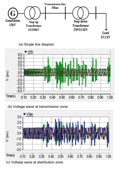
In this section, two case studies are presented. The first is the investigation of ferroresonance in 13.2 kV RDS. The second is the investigation of ferroresonance in the 13.2 kV RDS integrated with DG unit. The distribution is feeding from 230 kV overhead transmission line coming from generation plant as shown in Fig. 10a [112].
The system is lightly loaded, so the current values are insignificant. Despite the presence of ferroresonance, the current did not surpass the rated values. As a result, the focus of the research was on voltage values.
In the first case study, a light load is connected at the distribution transformer terminal. The system is normal, however, if one sending end conductor of the transmission line are being disconnected, the voltage fluctuated with a high value on both sides of the transformer. The capacitance of the transmission line interacts with the inductance of the distribution transformer. It results in ferroresonance as shown in Figs. 11b and 11c. Figs. 11b and 11c present the chaotic ferroresonance mode on both sides of the transformer at the moment of one of the transmission line conductors is cut. It is obvious that, the value of voltage rises more than 4 pu in the high voltage side and 2.7 pu in the low voltage side.
With the variation of load value, the increase of the load results in the disappearance of ferroresonance phenomenon even if one of the transmission line conductors is disconnected.
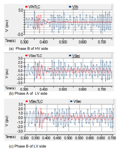
In the second case, the radial DS is penetrated with a DG unit. The 16 kV DG unit is connected to the distribution zone through 16/13.2 kV, 30 MVA, transformer. The described system is shown in Fig. 12a. With the penetration of DG into the system, the ferroresonance phenomenon is disappeared, even if one of the transmission line conductors or more are disconnected at any load value. In this case, the introduction of DG resulted in ferroresonance mitigation by altering the system topology. By studying all abnormal separation on DG and the transmission line, the ferroresonance was investigated only in the case of the separation of DG with the breakdown of phase A of the transmission line. Chaotic ferroresonance was investigated. It is found that the voltage value was increased on the low voltage side for 2.3 pu and for 4 pu on the high voltage side and 2.8 pu on the DG side as shown in Figs.12b and 12c.
All separation events implemented at the time 0.3 sec and the study conducted for one sec. The voltage levels resulted from ferroresonance phenomenon are extremely high. The abnormal switching action and the unexpected conductor failure may cause harmful damage to the power system parts. As a result, it’s critical to eliminate the factors that generate ferroresonance, such as loading nonlinear inductive elements with light or no load and failing to defend against phase failure.
Therefore, it is important to provide system with protection against phase failure. Incorporating DG into the radial DS can reduce the incidence of ferroresonance, but may result in worse ferroresonance in some cases. So, the researchers must guide their efforts for optimizing the use of DG and avoiding ferroresonance.

Mitigation of ferroresonance
Review of mitigation methods
Ferroresonance causes a significant increase in voltage and/or current, and this is considered a great threat to the parts of the electrical network from damage. Therefore, the researchers focused on reducing the occurrence of this phenomenon to avoid its major technical and economic problems.
Prevention of ferroresonance is divided into two ways. The first is protection methods provided for the electrical network to protect and reduce the bad effects of this phenomenon [113]. The second is the precautions taken to prevent the occurrence of ferroresonance into the electrical network.
Ferroresonance prevention methods, are all the methods and precautions taken by the electrical network operator to prevent the occurance of ferroresonance in the power system. Table 4 shows the most important precautions taken used to prevent ferroresonance. Ferroresonance mitigation techniques are all the techniques used to restrain the high values of voltage and current resulting from the ferroresonance [58]. Table 5 summarized the most important methods used to mitigate and its method of study.
Generally, Ferroresonance Suppression Circuits (FSC) are classified into three categories [33]. First, active FSC which consist of resonance circuit and operate with high impedance in normal frequency and low impedance in abnormal frequency to connect suppression element [26]. Second, passive FSC which contain of saturable reactor that saturate when the voltage value passed 1.5 pu then its impedance is reduced and connecting damping resistor [26]. Third, power electronics FSC which consist of two power electronic switches used to damp overvoltage during ferroresonance, and provide a resistive channel to ground [33].
Ref. [114] presented the using of resistor with two oneway controllable switches connected back to back implemented on the secondary side of the PT as a damping resistor to suppress ferroresonance. Ref. [115] presented the implementation of damping resistor connected with secondary winding of the transformer as suppress ferroresonance. Ref. [116] relied on the use of a resistance with an electronic switches implemented on PT secondary side to reduce the ferroresonance, but presented a different control circuit for the switches. It presented the control of the conduction of this resistance by a mechanical switch or a saturable reactor, having a saturation voltage. The saturation voltage is higher than the rated secondary voltage of the transformer but still quite near to it. The saturable reactor is saturated when ferroresonance occurs and the resistance can damp ferroresonance. Also, Ref. [117] used a parallel reactor with the secondary side of the PT for mitigating ferroresonance. Ref. [118] introduced the use of thyristor driven spontaneous close shunt reactors as a solution to ferroresonance on a power transmission line which reduces the duration of the high voltage result from ferroresonance.
A gas discharge lamp was used in [32] as a memristor emulator connected to the secondary of the CVT to minimise the ferroresonance. Ref. [119] introduced ferroresonance limiter consists of damping resistor resulted in eliminate of chaotic ferroresonance oscillations started with series capacitors controlled by thyristor in the CVT.
Ref. [120] introduced the design of two ferroresonance suppression circuit implemented on the step down side of the CVT. The first is to use a resistance only, and the second is to use RLC circuit. Refs. [71] and [109] recommended the implementation of damping resistor or air core reactor bank connected with transformer secondary winding as ferroresonance mitigation techniques. Refs. [110] and [111] presented the design of converter acted as damping resistor emulators to mitigate ferroresonance oscillation. Ref. [124] presented smart ferroresonance limiter circuit that consist of four magnetically coupled windings. The primary winding and the PT are linked in parallel. The secondary winding is utilised to reduce ferroresonance overvoltage value. The third and fourth windings are employed to detect ferroresonance beginning in the positive and negative half cycles of the transient overvoltage, sequentially.
Ref. [98] recommended the installation of overvoltage protection element at suitable locations to eliminate overvoltage generation from ferroresonance. Ref. [42] presented the using of Static Var Compensator (SVC) to mitigate ferroresonance by network voltage and reactive power control. Ref. [99] introduced the use of intelligent overcurrent protection, based on wavelet and neural network, to distinguish ferroresonance from transients cases. Ref. [127] presented a ferroresonance limiter, which consisted of anti-parallel IGBTs connected with series resonant LC. Fault current limiters with an inductive shielded core presented in [87] as a method to mitigate power transformers with chaotic ferroresonance.
Ref. [113] presented several ways to reduce the impact of ferroresonance, namely: connect nonlinear resistance to the high voltage side’s neutral point, install eliminating resistance to the secondary side of the transformer and grounding the neutral point via arc suppression coil. Ref. [128] presented the connection of metal oxide varistor to the secondary winding ofthe transformer as a means of limiting ferroresonance. Ref. [129] presented the inserting an air gap in the magnetic path of the voltage transformer core which resulting in the linearization of the magnetizing characteristic and lowering the risk of ferroresonance.
Ref. [107] introduced method to mitigate ferroresonance by adding damping reactor which is integrated with ferroresonance detection and suppression device to absorb the energy produced by ferroresonance. The opening of the opposite end of the line/transformer to de-energize the circuit breaker, before opening it, is presented in Ref. [130] as a solution to mitigate ferroresonance. Ref. [131] presented the use of ferroresonance eliminator consisted of resistance located at the three-phase PT’s primary side’s neutral point. Ref. [41] introduced grounding the power transformer by Petersen coil to mitigate ferroresonance. Ref. [132] presented three ferroresonance mitigation methods represented in grounding the PT primary side of nonlinear resistance, connecting a damping resistor in open delta winding of PT or choosing PT with best excitation characteristics. It turns out that the effect of DG on ferroresonance has not been thoroughly investigated and remains as a gap point. It was unclear how suppression ferroresonance methods would be implemented with the DGs. Furthermore, the effect of ferroresonance and DG on the DSs was not clarified, and researchers did not pay enough attention to solutions to this problem in the DSs.
Implementation of series ferroresonance suppression circuit
The Tuned LC Circuit (TLCC) was implemented by connecting a capacitor and an inductor in series and adjusting their values in resonance state according to Eq. (1) to have a negligible impedance at the system’s steady-state frequency [127]. TLCC impedance reduced the amplitude of overvoltage to an acceptable level under abnormal conditions. In this study, TLCC will be tested in both radial system and radial system integrated with DG that given in section IV. In the normal state, TLCC circuit did not cause a voltage drop, and in the abnormal condition, it mitigates the overvoltage value in both cases as given in the following paragraphs.
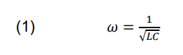
Table 4. Ferroresonance preventing methods

Table 5. Ferroresonance mitigating techniques
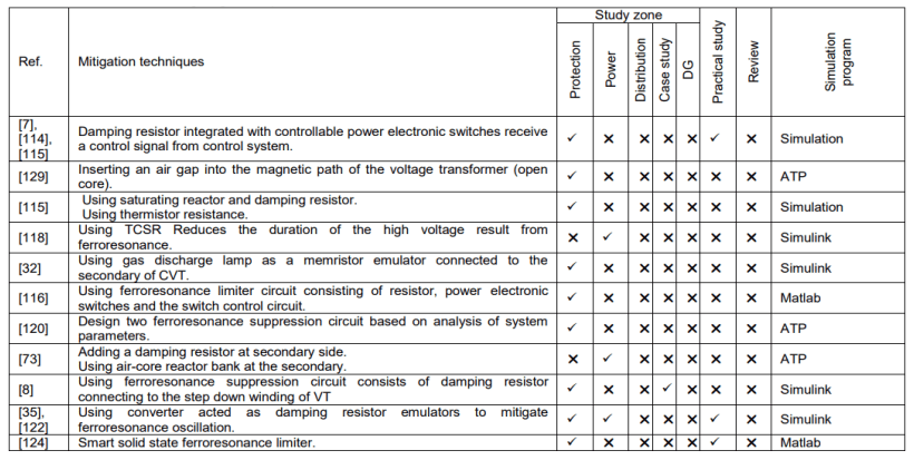

Table 6. Voltage of radial system with and without DG

Table 7. Voltage of radial system integrated with DG with and without TLCC

TLCC is implemented on the low voltage side of the transformer at the RDS described in section IV resulted in ferroresonance mitigation
The value of the voltage is reduced as presented in Table 6. TLCC results in suppression of the ferroresonance after 0.08 sec from the separation. TLCC’s efficiency in decreasing the overvoltage value is demonstrated in Fig. 13.
Applying TLCC with the radial system integrated with DG results in ferroresonance mitigation. The TLCC is implemented on the DG side of the distribution transformer. It results in decreasing the overvoltage values presented in Table 7. TLCC’s efficiency in decreasing the overvoltage value is demonstrated in Fig. 14.

Conclusion
In this paper, a state of art of ferroresonance and the most obvious signs of ferroresonance, as well as the analytical methods used to detect it, are presented. This phenomenon is verified by simulating its equivalent circuit using PSCAD/EMTDC software. The investigation of ferroresonance in power transformers and the effect of changing the load on the phenomenon are verified. It is concluded from transformer study that it is preferable to load transformers at more than 10% of their capacity to avoid ferroresonance.
This paper also studies the penetration of the DG into the radial system and the extent of its impact on the occurrence or prevention of ferroresonance as a case study. Results showed that the penetration of DGs into the distribution zone has an active role in mitigating the investigation of ferroresonance. The ferroresonance is appeared only during disconnecting the DG and a phase of the transmission line with keeping the DG transformer connected to the distribution side. The rate of ferroresonance occurrence in the case of DG integration is lower than that occurs in the case of DG unintegrated distribution system due to the need for separating more than one position at the same time.
Finally the analytical methods used to prevent this phenomena are presented and compared. Also the TLCC method was implemented to suppress ferroresonance. The results proved that the system penetrated with DG responds faster to TLCC ferroresonance mitigation method more than the distribution system without DG.
REFERRENCES
[1] S. P. Ang, Ferroresonance simulation studies of transmission systems, PHD, Faculty of Engineering and Physical Sciences. Manchester: the university of manchester, 2010.
[2] S. Poomima and C. P. Sugumaran, “Identification of ferroresonance phenomena using wavelet transforms,” in 2016 International Conference on Control, Instrumentation, Communication and Computational Technologies (ICCICCT), 2016, pp. 126–131.
[3] V. Arun kumar, S. Elango, M. Prabu, B. Ramraj, “Transient Overvoltages And Its Prevention And Protection,” ” International Journal of Engineering Trends and Technology., vol. 68, no. 3, pp. 22–25, 2020.
[4] A. Akinrinde, A. Swanson, and R. Tiako, “Investigation of Temporary Overvoltage on Microgrid with Emphasis on Ferroresonance,” Int. J. Eng. Res. Africa, vol. 39, pp. 32–46, 2018,
[5] P. H. B. de S. Pinheiro, M. L. C. Vidal, F. F. da Rocha, B. W. França, and M. Z. Fortes, “Ferroresonance evaluation on capacitor voltage transformers,” Electr. Eng., vol. 102, no. 3, pp. 1775–1783, 2020,
[6] V. Valverde, J. Mazón, G. Buigues, and I. Zamora, “Ferroresonance suppression in voltage transformers,” Prz. Elektrotechniczny, vol. 88, no. 1 A, pp. 137–140, 2012.
[7] M.Yang, W. Sima, P. Duan, M. Zou, D. Peng, Q. Yang, Q. Duan,, “Electromagnetic transient study on flexible control processes of ferroresonance,” Int. J. Electr. Power Energy Syst., vol. 93, pp. 194–203, 2017.
[8] S. J. Kruger and J. A. de Kock, “Ferroresonance: A Review of the Phenomenon and Its Effects,” 2021 Southern African Universities Power Engineering Conference/Robotics and Mechatronics/Pattern Recognition Association of South Africa, 2021, pp. 1–6.
[9] S. Hassan, M. Vaziri, and S. Vadhva, “Review of ferroresonance in power distribution grids,” 2011 IEEE International Conference on Information Reuse Integration, 2011, pp. 444–448.
[10] L. V Bykovskaya and V. Bykovskiyi, “Simulation of a Voltage Transformer with a Magnetic Core Made of Amorphous Steels,” 2020 International Conference on Industrial Engineering, Applications and Manufacturing (ICIEAM), 2020, pp. 1–5.
[11] L. Zhao, X. Chen, L. Ye, Y. Yang, S. Wang, and B. Yu, “Research on Ferroresonance of Electromagnetic Voltage Transformer in 550kV HGIS,” 2019 IEEE 3rd International Conference on Circuits, Systems and Devices (ICCSD), 2019, pp. 34–38.
[12] V. Valverde, G. Buigues, A. Mazon, I. Zamora, and I. Albizu, “Ferroresonant Configurations in Power Systems,” Renew. energy power Qual. J., pp. 474–479, 2012.
[13] M. Xu and L. Zhu, “Ferro-resonance Overvoltage Identification Using Earth Capacitance and Excitation Inductance of Ratio Method,” 2017 International Conference on Advances in Materials, Machinery, Electrical Engineering (AMMEE), 2017, pp. 335–359.
[14] M. Mikhak-Beyranvand, B. Rezaeealam, J. Faiz, and A. Rezaei-Zare, “Impacts of ferroresonance and inrush current forces on transformer windings,” IET Electr. Power Appl., vol.13, no. 7, pp. 914–921, 2019.
[15] S. Rezaei, “Prevention of False Operation of Distance Relay in Ferroresonance,” Int. J. Adv. Res. Electr. Electron. Instrum. Eng., vol. 5, 2016.
[16] S. Rezaei, “Impact of Ferroresonance on protective relays in Manitoba Hydro 230 kV electrical network,” 2015 IEEE 15th International Conference on Environment and Electrical Engineering (EEEIC), 2015, pp. 1694–1699.
[17] N. Yang, Y. Han, C. Wu, R. Jia, and C. Liu, “Dynamic analysis and fractional-order adaptive sliding mode control for a novel fractional-order ferroresonance system,” Chinese Phys. B, vol.26, no. 8, p. 80503, 2017,
[18] K. Solak, W. Rebizant, and M. Kereit, “Detection of Ferroresonance Oscillations in Medium Voltage Networks,” Energies, vol. 13, no. 16, p. 4129, 2020,
[19] D. Zhang, X. Hu, H. Zhang, H. Yu, and Y. Shen, “Ferroresonance Analysis of 500kV GIS Substation during Commissioning Process,” IOP Conf. Ser. Earth Environ. Sci., vol. 514, p. 42042, 2020,
[20] W. Sima, M. Zou, M. Yang, D. Peng, and Y. Liu, “Saturable reactor hysteresis model based on Jiles–Atherton formulation for ferroresonance studies,” Int. J. Electr. Power Energy Syst., vol. 101, pp. 482–490, 2018,
[21] M. Kanálik, A. Margitová, B. Dolník, D. Medveď, M. Pavlík, and J. Zbojovský, “Analysis of low-frequency oscillations of electrical quantities during a real black-start test in Slovakia,” Int. J. Electr. Power Energy Syst., vol. 124, p. 106370, 2021,
[22] E. O. Egorova, “development of the coil volume method for time-domain simulation of internal faults in transformers,” PHD Thesis, michigan technological university, 2019.
[23] S.E. Zirka, Y.I. Moroz, A.V. Zhuykov, D.A. Matveev, M.A. Kubatkin, M.V. Frolov, M. Popov, Eliminating VT uncertainties in modeling ferroresonance phenomena caused by single phase-to-ground faults in isolated neutral network,” Int. J. Electr. Power Energy Syst., vol. 133, no. May, p. 107275, 2021.
[24] L. Zhen, C. JianBin, X. Yuan, X. Zhen, W. Shenhua, and W. Tian, “The ferroresonance of 10kV distribution PT during live working operation,” The 16th IET International Conference on AC and DC Power Transmission (ACDC), 2021, pp. 1641–1646.
[25] Y. Zhang, S. Xie, N. Jiang, Z. Zhao, D. Luo, N. Wang and J. Li “Analysis of Pt Ferroresonance based on Excitation Characteristic and Self-Excitation Mechanism,” J. Phys. Conf. Ser., vol. 1732, p. 012180, 2021.
[26] M. Tajdinian, M. Allahbakhshi, S. Biswal, O. P. Malik, and D. Behi, “Study of the Impact of Switching Transient Overvoltages on Ferroresonance of CCVT in Series and Shunt Compensated Power Systems,” IEEE Trans. Ind. Informatics, vol. 16, no. 8, pp. 5032–5041, 2020.
[27] A. Arroyo, R. Martinez, M. Manana, A. Pigazo, and R. Minguez, “Detection of ferroresonance occurrence in inductive voltage transformers through vibration analysis,” Int. J. Electr. Power Energy Syst., vol. 106, pp. 294–300, 2019.
[28] P. Sridharan and P. S. C, “Memristor emulator – a nonlinear load for reduction of ferroresonance in a single-phase transformer,” Circuit World, vol. 47, no. 1, pp. 87–96, 2020.
[29] I. R. Pordanjani, X. Liang, Y. Wang, and A. Schneider, “Single-Phase Ferroresonance in an Ungrounded System during System Energization,” IEEE Trans. Ind. Appl., vol. 7, no. c, 2021.
[30] K. Solak and W. Rebiant, “Modeling of Ferroresonance Phenomena in MV Networks,” in 2018 IEEE Electrical Power and Energy Conference (EPEC), 2018, pp. 1–6.
[31] A. Heidary, K. Rouzbehi, H. Radmanesh, and J. Pou, “Voltage Transformer Ferroresonance: An Inhibitor Device,” IEEE Trans. Power Deliv., vol. 35, no. 6, pp. 2731-2733, 2020.
[32] V. Mohan, S. Poornima, and C. P. Sugumaran, “Mitigation of Ferroresonance in Capacitive Voltage Transformer Using Memelements,” 2019 International Conference on High Voltage Engineering and Technology (ICHVET), 2019, pp. 1–5.
[33] M. Tajdinian, M. Allahbakhshi, B. Behdani, D. Behi, and A. Goodarzi, “Probabilistic framework for vulnerability analysis of coupling capacitor voltage transformer to ferroresonance phenomenon,” IET Sci. Meas. Technol., vol. 14, no. 3, pp. 344–351, 2020.
[34] I. G. Ngurah Satriyadi Hernanda, I. M. Yulistya Negara, D. A. Asfani, D. Fahmi, M. R. Ramadhan, and B. K. Yegar Sahaduta, “Study of Ferroresonance in 150 kV High Voltage Inductive Voltage Transformer,” in 2020 International Seminar on Intelligent Technology and Its Applications (ISITIA), 2020, pp. 386–391.
[35] M. Tajdinian, M. Allahbakhshi, S. Biswal, O. P. Malik, and D. Behi, “Study of the Impact of Switching Transient Overvoltages on Ferroresonance of CCVT in Series and Shunt Compensated Power Systems,” IEEE Trans. Ind. Informatics, vol. 16, no. 8, pp. 5032–5041, 2020.
[36] E. A. Badran, M. E. M. Rizk, and M. H. Abdel-Rahman, “Investigation of ferroresonance in offshore wind farms.,” J. Am. Sci., vol. 7, no. 9, pp. 941–950, 2011.
[37] W. Farm, A. Akinrinde, and A. Swanson, “Investigation and Mitigation of Temporary Overvoltage Caused by DeEnergization on an,” 2020.
[38] S. Aref, A. S. Anaraki, and D. A. Zarchi, “Probability Evaluation of Occurrence of Ferroresonance in Montazer Qaem 63kV Substation,” 2020 14th International Conference on Protection and Automation of Power Systems (IPAPS), 2019, pp. 7–13.
[39] A. Nassar, A.-M. Taalab, M. Izzularab, and N. Elkalashy, “Investigation of Resonance and Ferroresonance Overvoltages due to Cable-Transformer Interactions,” ERJ. Eng. Res. J., vol. 43, no. 4, pp. 261–271, 2020.
[40] M. Polewaczyk, S. Robak, and M. Szewczyk, “Investigation on ferroresonance due to power transformer energization in high voltage 400 kV transmission grid,” Arch. Electr. Eng., vol. 68, no. 4, pp. 771–786, 2019.
[41] I. G. Ngurah Satriyadi Hernanda, I. M. Yulistya Negara, D. A. Asfani, D. Fahmi, M. Wahyudi, and K. S. Anugrah, “Study of Petersen Coil Grounding System Inductance Variation on Ferroresonance in 150 kV Transformer,” in 2018 International Seminar on Intelligent Technology and Its Applications (ISITIA), 2018, pp. 141–146.
[42] S. Rezaei, “Impact of transmission line and plant outage on ferroresonance in AC transmission system and new suppression method,” in 13th IET International Conference on AC and DC Power Transmission (ACDC 2017), 2017, pp. 1–6.
[43] M. Yang, W. Sima, Q. Yang, J. Li, M. Zou, and Q. Duan, “Nonlinear characteristic quantity extraction of ferroresonance overvoltage time series,” IET Gener. Transm. Distrib., vol. 11, no. 6, pp. 1427–1433, 2017.
[44] I. M. Yulistya Negara, I. G. Ngurah Satriyadi Hernanda, D. A. Asfani, D. Fahmi, M. Wahyudi, and R. Hidayat, “Comparison of Ferroresonance Response on Three Phases Transformer with Different Core Material: M5 and ZDKH,” 2018 International Seminar on Intelligent Technology and Its Applications (ISITIA), 2018, pp. 129–134.
[45] M. Zou, “Accurate simulation model for a three-phase ferroresonant circuit in EMTP–ATP,” Int. J. Electr. Power Energy Syst., vol. 107, pp. 68–77, 2019.
[46] R. S. Pal and M. Roy, “Study and Verification of Ferroresonance Simulated with Rudenburg’s Method,” in 2021 Innovations in Energy Management and Renewable Resources(52042), 2021, pp. 1–5.
[47] D. K. Buslaev, J. K. Ochkovskaya, and L. D. Ziles, “Ferroresonance occurrence conditions in a simple nonlinear circuit,” Proc. 3rd 2021 Int. Youth Conf. Radio Electron. Electr. Power Eng. REEPE 2021, pp. 2–6, 2021.
[48] S. Boutora and H. Bentarzi, “Ferroresonance Study Using False Trip Root Cause Analysis,” Energy Procedia, vol. 162, pp. 306–314, 2019.
[49] M. S. H. Bini, S. P. Ang, K. S. K. Yeo, A. Khalil, and S. Jaafar, “Analytical prediction of initiation of ferroresonance modes,” J. Phys. Conf. Ser., vol. 1529, p. 32087, 2020,
[50] I. M. Y. Negara, D. A. Asfani, I. G. N. S. Hernanda, D. Fahmi, Verdiansyah, and B. K. Aji, “Wavelet Transformation Selection for Detection of Ferroresonance Behaviour,” in 2019 International Seminar on Intelligent Technology and Its Applications (ISITIA), 2019, pp. 253–258.
[51] M. Sowa and Ł. Majka, “Ferromagnetic core coil hysteresis modeling using fractional derivatives,” Nonlinear Dyn., vol. 101, no. 2, pp. 775–793, 2020.
[52] M. Mikhak-Beyranvand, J. Faiz, A. Rezaei-Zare, and B. Rezaeealam, “Electromagnetic and thermal behavior of a single-phase transformer during Ferroresonance considering hysteresis model of core,” Int. J. Electr. Power Energy Syst., vol. 121, p. 106078, 2020.
[53] M. Hajizadeh, I. Safinejad, and N. Amirshekari, “Study and comparison of the effect of conventional, low losses and amorphous transformers on the ferroresonance occurrence in electric distribution networks,” CIRED – Open Access Proc. J., vol. 2017, no. 1, pp. 865–869, 2017.
[54] M. I. Mosaad and N. A. Sabiha, “Ferroresonance Overvoltage Mitigation using STATCOM for Grid-Connected Wind Energy Conversion Systems,” J. Mod. Power Syst. Clean Energy, pp.1–9, 2021.
[55] A. I. Abdi, J. J. Walker, and J. S. Djeumen, “The Effect Of Cable Length On Ferroresonance In Low-Loss Distribution Transformers,” in 2021 Southern African Universities Power Engineering Conference/Robotics and Mechatronics/Pattern Recognition Association of South Africa (SAUPEC/RobMech/PRASA), 2021, pp. 1–4.
[56] S. O. Koledowo, E. C. Ashigwuike, and A. Bawa, “A study of ferroresonance in underground distribution network for 15MVA, 33/11 kV injection substation,” Niger. J. Technol., vol.39, pp. 219–227, 2020.
[57] N. Thanomsat, B. Plangklang, and H. Ohgaki, “Analysis of Ferroresonance Phenomenon in 22 kV Distribution System with a Photovoltaic Source by PSCAD/EMTDC,” Energies, vol. 11, p. 1742, 2018.
[58] A. B. Nassif, M. Dong, S. Kumar, and G. Vanderstar, “Managing Ferroresonance Overvoltages in Distribution Systems,” in 2019 IEEE Canadian Conference of Electrical and Computer Engineering (CCECE), 2019, pp. 1–4.
[59] A. Abdullah, “A Ferroresonance Study of a 240 MW Solar PV Project,” 2018 IEEE Industry Applications Society Annual Meeting (IAS), 2018, pp. 1-4.
[60] S. P. Ang, J. Peng, and Z. Wang, “Identification of key circuit parameters for the initiation of ferroresonance in a 400-kV transmission system,” 2010 International Conference on High Voltage Engineering and Application, 2010, pp. 73–76.
[61] B. Behdani, M. Allahbakhshi, and M. Tajdinian, “On the impact of geomagnetically induced currents in driving series capacitor compensated power systems to ferroresonance,” Int. J. Electr. Power Energy Syst., vol. 125, p. 106424, 2021.
[62] L. Chen, J. Wang, W. Sima, and T. Yuan, “Classification of Fundamental Ferroresonance, Single Phase-to-Ground and Wire Breakage Over-Voltages in Isolated Neutral Networks,” Energies, vol. 4, no. 9, pp. 1301–1320, 2011.
[63] Ł. Majka, “Fractional Derivative Approach in Modeling of a Nonlinear Coil for Ferroresonance Analyses,” in Non-Integer Order Calculus and its Applications, 2019, pp. 135–147.
[64] M. Navaei, A. A. Abdoos, and M. Shahabi, “A new control unit for electronic ferroresonance suppression circuit in capacitor voltage transformers,” Int. J. Electr. Power Energy Syst., vol.99, pp. 281–289, 2018.
[65] I. M. Bedritskiy and K. K. Jurayeva, “Estimation of Errors in Calculations of Coils with Ferromagnetic Core,” in 2020 International Conference on Industrial Engineering, Applications and Manufacturing (ICIEAM), 2020, pp. 1–6.
[66] M. Kutija and L. Pravica, “Effect of harmonics on ferroresonance in low voltage power factor correction system—A case study,” Appl. Sci., vol. 11, no. 10, 2021.
[67] M. Wahyudi, I. M. Yulistya Negara, D. Anton Asfani, I. G. N. S. Hernanda, and D. Fahmi, “Investigation of Ferroresonance Physical Behaviours on Three Phases Transformer with Unsymmetrical Core Leg,” in 2018 International Seminar on Application for Technology of Information and Communication, 2018, pp. 66–70.
[68] J. Wisniewski, E. Anderson, and J. Karolak, “Search for network parameters preventing ferroresonance occurrence,” in 2007 9th International Conference on Electrical Power Quality and Utilisation, 2007, pp. 1–6.
[69] M. Esmaeili, M. Rostami, G. B. Gharehpetian, and C. P. McInnis, “Ferroresonance After Islanding of Synchronous Machine-Based Distributed Generation,” Can. J. Electr. Comput. Eng., vol. 38, no. 2, pp. 154–161, 2015.
[70] F. In and P. Systems, 13 – Ferroresonance in power systems energiforskrapport-2017-457. Report, 2017.
[71] S. Chen and H. Yu, “A Review on Overvoltages in Microgrid,” in 2010 Asia-Pacific Power and Energy Engineering Conference, 2010, pp. 1–4.
[72] R. Zhang, H. Li, S. P. Ang, and Z. Wang, “Complexity of ferroresonance phenomena: sensitivity studies from a singlephase system to three-phase reality,” in 2010 International Conference on High Voltage Engineering and Application, 2010, pp. 172–175.
[73] B. Baldwin, S. S. Sabade, and S. Joshi, “A Study of Ferroresonance & Mitigation Techniques April,” michigan university, 2013.
[74] K. Milicevic, E. K. Nyarko, and I. Biondic, “Chua’s model of nonlinear coil in a ferroresonant circuit obtained using Dommel’s method and grey box modelling approach,” Nonlinear Dyn., vol. 86, no. 1, pp. 51–63, 2016.
[75] N. Thanomsat and B. Plangklang, “Ferroresonance phenomenon in PV system at LV side of three phase power transformer using of PSCAD simulation,” 2016 13th International Conference on Electrical Engineering/Electronics, Computer, Telecommunications and Information Technology (ECTI-CON), 2016, pp. 1-4.
[76] A. Akinrinde, A. Swanson, and R. Tiako, “Dynamic Behavior of Wind Turbine Generator Configurations during Ferroresonant Conditions,” Energies, vol. 12, p. 639, 2019.
[77] F. Ben Amar and R. Dhifaoui, “Analytical Approach for the Systematic Research of the Periodic Ferroresonant Solutions in the Power Networks,” Energy Power Eng., vol. 03, pp. 450–477, 2011,
[78] L. Jiaxin, L. Xuchen, W. Yanan, W. Defu, and T. Jianeng, “Discriminate Method of Power Frequency Ferroresonance in System with Non-Effectively Earthed Neutral of Three-Phase Enclosed GIS,” in 2018 China International Conference on Electricity Distribution (CICED), 2018, pp. 801–805.
[79] T. Şengüler and S. Şeker, “Continuous wavelet transform for ferroresonance detection in power systems,” Electr. Eng., vol. 99, no. 2, pp. 595–600, 2017,
[80] A. Karrar, M. Ahmed, A. Ali, S. Mohammed, R. Hay, and R. Johnson, “Investigation of Ferroresonance Incidents in the EPB Distribution Network,” 2018.
[81] Q. Wu, D. Deswal, M. Yang, S. Wang, and F. de León, “Experimental Study of Magnetic Effects of Steel Tanks on Three-Phase Transformer Transients,” IEEE Trans. Power Deliv., vol. 35, no. 2, pp. 665–673, 2020.
[82] Ł. Majka and M. Klimas, “Diagnostic approach in assessment of a ferroresonant circuit,” Electr. Eng., vol. 101, no. 1, pp.149–164, 2019.
[83] R. Cetina, V. Torres, and M. Madrigal, “Simulations of ferroresonance in transformers using ATP (Alternative Transient Program),” in 2018 IEEE International Autumn Meeting on Power, Electronics and Computing (ROPEC), 2018, pp. 1–7.
[84] R. El Mahayni, A. Gheeth, J. Thomai, and R. Sudhir, “Ferroresonance measurements and modeling; a waveform is worth a thousand words,” in 2018 Petroleum and Chemical Industry Conference Europe (PCIC Europe), 2018, pp. 1–10.
[85] A. H. Abu Bakar, S. A. Khan, T. Kwang, and N. Abd Rahim, “A Review of Ferroresonance in Capacitive Voltage Transformer,” IEEJ Trans. Electr. Electron. Eng., vol. 10, 2015,
[86] V. George, G. K. Kumaran, J. Shivashankari, and S. Ashok, “Analysis of ferroresonance in a hybrid micro-grid with multiple distributed resources,” in 2016 International Conference on Electrical, Electronics, and Optimization Techniques (ICEEOT), 2016, pp. 1286–1291.
[87] H. Fordoei and S. A. Afsari, “Elimination of chaotic ferroresonance in power transformer by ISFCL,” Int. J. Electr. Power Energy Syst., vol. 68, 2015.
[88] S. Emiroglu, Y. Uyaroglu, and T. E. Gümüş, “Recursive backstepping control of ferroresonant chaotic oscillations consisting between grading capacitor with nonlinear inductance of voltage transformer,” Eur. Phys. J. Spec. Top., vol. 230, no. 7, pp. 1829–1837, 2021.
[89] A. Heidary, H. Radmanesh, A. Bakhshi, S. Samandarpour, K. Rouzbehi, and N. Shariati, “Compound ferroresonance overvoltage and fault current limiter for power system protection,” IET Energy Syst. Integr., vol. 2, no. 4, pp. 325–330, 2020.
[90] S Poornima, “Suppression of ferroresonance using passive memristor emulator” , Chin. Phys. Vol. 30, no. 6, P.068401,2021.
[91] Z. Abdul-Malek, K. Mehranzamir, B. Salimi, H. Nabipour Afrouzi, and S. Vahabi Mashak, “Investigation of ferroresonance mitigation techniques in voltage transformer using ATP-EMTP simulation,” J. Teknol. (Sciences Eng., vol. 64, no. 4, pp. 85–95, 2013,
[92] S. Rezaei, “Power Oscillation Due to Ferroresonance and Subsynchronous Resonance,” Power System Stability, Kenneth Eloghene Okedu, IntechOpen, 2019.
[93] V. Valverde, A. J. Mazón, I. Zamora, and G. Buigues, “Ferroresonance in voltage transformers: Analysis and simulations,” Renew. Energy Power Qual. J., vol. 1, no. 5, pp. 465–471, 2007,
[94] M. Akbari, A. Rezaei-Zare, M. A. M. Cheema, and T. Kalicki, “Air gap inductance calculation for transformer transient model,” IEEE Trans. Power Deliv., vol. 36, no. 1, pp. 492–494, 2021.
[95] A. Tokić, M. Kasumović, M. Pejić, V. Milardić, and T. Cetin Akinci, “Determination of single-phase transformer saturation characteristic by using Nelder–Mead optimization method,” Electr. Eng., 2021.
[96] R. Perez Pineda, R. Rodrigues, and A. Aguila Tellez, “Analysis and Simulation of Ferroresonance in Power Transformers using Simulink,” IEEE Lat. Am. Trans., vol. 16, no. 2, pp. 460–466, 2018.
[97] J. A. Corea-Araujo, J. A. Martinez-Velasco, F. GonzálezMolina, J. A. Barrado-Rodrigo, L. Guasch-Pesquer, and F. Castro-Aranda, “Validation of single-phase transformer model for ferroresonance analysis,” Electr. Eng., vol. 100, no. 3, pp. 1339–1349, 2018.
[98] R. Minkner and J. Schmid, “Voltage Measurement,” in The Technology of Instrument Transformers : Current and Voltage Measurement and Insulation Systems, Wiesbaden: Springer Fachmedien Wiesbaden, 2022, pp. 139–233.
[99] S. Rezaei, “Intelligent overcurrent protection during Ferroresonance in smart distribution grid,” in 2019 IEEE International Conference on Environment and Electrical Engineering and 2019 IEEE Industrial and Commercial Power Systems Europe (EEEIC / I&CPS Europe), 2019, pp. 1–6.
[100] O. Akgün, T. C. Akinci, G. Erdemir, and S. Seker, “Analysis of instantaneous frequency, instantaneous amplitude and phase angle of ferroresonance in electrical power networks,” J. Electr. Eng., vol. 70, pp. 494–498, 2019.
[101] Z. Emin et al., “Resonance and Ferroresonance in Power Networks,” Cigré Technical Brochure 569 – WG C4.307, Paris, France. 2014.
[102] A. Djebli, F. Aboura, L. Roubache, and O. Touhami, “Impact of the eddy current in the lamination on ferroresonance stability at critical points,” Int. J. Electr. Power Energy Syst., vol. 106, pp. 311–319, 2019.
[103] R. Saravanaselvan and R. Ramanujam, “Detection and analysis of isolated subharmonic ferroresonant solutions in power transformers,” Eur. Trans. Electr. Power, vol. 21, no. 1, pp. 82–88, 2011.
[104] T. C. Akinci, E. Ayaz, S. Yildirim Unnu, and S. Seker, “A review study on ferroresonance phenomena in power systems,” in International Conference on Technics, Technologies and Education ICTTE, 2014.
[105] Ł. Majka and M. Klimas, “Diagnosis of a ferroresonance type through visualisation,” ITM Web Conf., vol. 28, p. 1039, 2019.
[106] A. Akinrinde, A. Swanson, R. Tiako, A. Emtp, and S. Matlab, “Effect of Ferroresonance on Wind Turbine: Comparison of Atp/Emtp and Matlab/Simulink,” Indones. J. Electr. Eng. Comput. Sci., vol. 14, pp. 1581–1594, 2019.
[107] S. M. H. Hosseini and Yasertoghaniholari, “Ferroresonance Study on the VT in the Karoon 4 Power Plant 400 kV GIS Substation,” Res. J. Appl. Sci. Eng. Technol., vol.7, pp. 1721–1728, 2014.
[108] C. Pallem, D. Mueller, and M. McVey, “Case Study of a New Type of Ferroresonance in Solar Power Plants,” in 2019 IEEE Power Energy Society General Meeting (PESGM), 2019, pp. 1–5.
[109] S. Mišák and J. Fulneček, “The influence of ferroresonance on a temperature of voltage transformers in undeground mines,” in 2017 18th International Scientific Conference on Electric Power Engineering (EPE), 2017, pp. 1–4.
[110] R. Martinez, A. Pigazo, M. Manana, A. Arroyo, and R. Minguez, “Ferroresonance Detection in Voltage Transformers Through Vibration Monitoring,” in Advances in Condition Monitoring of Machinery in Non-Stationary Operations, 2019, pp. 269–277.
[111] W. Sima, D. Peng, M. Yang, P. Sun, B. Zou, and Z. Xiong, “Reversible Wideband Hybrid Model of Two-Winding Transformer including the Core Nonlinearity and EMTP Implementation,” IEEE Trans. Ind. Electron., vol. 68, no. 4, pp. 3159–3169, 2021.
[112] Manitoba Hydro International “Chapter 4 -“PSCAD Cookbook Ferroresonance,” 2018.
[113] Z. He, X. Li, J. Qin, and H. Huang, “Study on Ferroresonance Over-Voltage Based on Harmonic Elimination Device,” in 2018 International Conference on Virtual Reality and Intelligent Systems (ICVRIS), 2018, pp. 460–465.
[114] W. Sima, M. Yang, Q. Yang, T. Yuan, and M. Zou, “Simulation and experiment on a flexible control method for ferroresonance,” IET Gener. Transm. Distrib., vol. 8, no. 10, pp. 1744–1753, 2014.
[115] E. Price, “A tutorial on ferroresonance,” in 2014 67th Annual Conference for Protective Relay Engineers, 2014, pp. 676–704.
[116] H. Radmanesh and S. H. Fathi, “Stabilizing Ferroresonance Oscillations in Voltage Transformers Using Limiter Circuit,” Electronics, vol. 16, pp. 145–152, 2012.
[117] K.-. Tseng and P.-. Cheng, “Mitigating 161 kV electromagnetic potential transformers’ ferroresonance with damping reactors in a gas-insulated switchgear,” IET Gener. Transm. Distrib., vol. 5, no. 4, pp. 479–488, 2011.
[118] A. M. Matinyan, M. V Peshkov, V. N. Karpov, and N. A. Alekseev, “Study of Transient Ferroresonance on a PTL with a TCSR,” Power Technol. Eng., vol. 51, no. 3, pp. 346–350, 2017.
[119] A. Abbasi, S. Fathi, and A. Mihankhah, “Elimination of Chaotic Ferroresonant Oscillations Originated from TCSC in the Capacitor Voltage Transformer,” IETE J. Res., vol. 64, pp.1–13, 2017.
[120] J. Izykowski, E. Rosolowski, P. Pierz, and M. M. Saha, “Design of ferroresonance suppression circuit for capacitive voltage transformer – analytical approach supported by simulation,” in 2016 Power Systems Computation Conference (PSCC), 2016, pp. 1–7.
[121] A. Rezaei-Zare, A. H. Etemadi, and R. Iravani, “Challenges of Power Converter Operation and Control Under Ferroresonance Conditions,” IEEE Trans. Power Deliv., vol.32, no. 6, pp. 2380–2388, 2017.
[122] E. Bayona et al., “Electronic resistor emulators for ferroresonance damping in MV transformers,” IET Renew. Power Gener., vol. 13, no. 1, pp. 201–208, 2019.
[123] E. Bayona et al., “Ferroresonance Mitigation Device in Voltage Transformers with a Flyback based Resistor Emulator,” in 2018 IEEE 19th Workshop on Control and Modeling for Power Electronics (COMPEL), 2018, pp. 1–5.
[124] A. Heidary and H. Radmanesh, “Smart solid-state ferroresonance limiter for voltage transformers application: principle and test results,” IET Power Electron., vol. 11, no. 15, pp. 2545–2552, 2018.
[125] E. Cazacu, L. Petrescu, and V. Ioniţă, “Ferroresonance modes determination of single-phase toroidal transformers,” in 2017 15th International Conference on Electrical Machines, Drives and Power Systems (ELMA), 2017, pp. 358–361.
[126] W. Chunbao, T. Lijun, and Q. Yinglin, “A study on factors influencing ferroresonance in distribution system,” in 2011 4th International Conference on Electric Utility Deregulation and Restructuring and Power Technologies (DRPT), 2011, pp. 583–588.
[127] H. Radmanesh, “Distribution Network Protection Using Smart Dual Functional Series Resonance-Based Fault Current and Ferroresonance Overvoltage Limiter,” IEEE Trans. Smart Grid, vol. 9, no. 4, pp. 3070–3078, 2018.
[128] A. Abbasi, M. Rostami, A. Gholami, and H. Abbasi, “Analysis of Chaotic Ferroresonance Phenomena in Unloaded Transformers Including MOV,” Energy Power Eng., vol. 03, 2011.
[129] D. Krajtner and Igor!, “Influence of HV inductive voltage transformers core design to the ferroresonance occurrence probability.” International Conference on Power Systems Transient (IPST), 2015.
[130] Y. Wang, X. Liang, I. R. Pordanjani, R. Cui, A. Jafari, and C. Clark, “Ferroresonance Causing Sustained High Voltage at A De-energized 138 kV Bus: A Case Study,” in 2019 IEEE/IAS 55th Industrial and Commercial Power Systems Technical Conference (I CPS), 2019, pp. 1–9.
[131] Y. Chen, Y. Li, J. Wu, and K. Liu, “Analysis of Sequences Harmonics Measurement Impact Using Potential Transformers Grounded through Ferroresonance Eliminator,” Appl. Mech. Mater., vol. 615, pp. 215–221, 2014.
[132] H. Gao, P. W. Yang, C. H. Liu, J. S. Zhang, and T. Wu, “Analysis and Simulation of Ferroresonance Mechanism of Potential Transformer Based on Harmonic Balance Method,” {IOP} Conf. Ser. Earth Environ. Sci., vol. 701, no. 1, p. 12071, 2021.
[133] M. Monadi, A. Luna, J. I. Candela, J. Rocabert, M. Fayezizadeh, and P. Rodriguez, “Analysis of ferroresonance effects in distribution networks with distributed source units,” in IECON 2013 – 39th Annual Conference of the IEEE Industrial Electronics Society, 2013, pp. 1974–1979.
[134] M. Yang, W. Sima, L. Chen, P. Duan, P. Sun, and T. Yuan, “Suppressing ferroresonance in potential transformers using a model-free active-resistance controller,” Int. J. Electr. Power Energy Syst., vol. 95, pp. 384–393, 2018.
[135] J. Horak, “A review of ferroresonance,” in 57th Annual Conference for Protective Relay Engineers, 2004, 2004, pp. 1–29.
Authors: Eng. Mohamed M. El-Shafhy, E-mail: m.elshafhy@sha.edu.eg, dr. inż. Alaa M. Abdel-hamed, E-mail: a.mohammed@sha.edu.eg, prof. dr hab. inż Ebrahim A. Badran, E-mail: ebadran@mans.edu.eg.
Source & Publisher Item Identifier: PRZEGLĄD ELEKTROTECHNICZNY, ISSN 0033-2097, R. 98 NR 11/2022. doi:10.15199/48.2022.11.01
