Published by Konrad DĄBAŁA1, Marian P. KAZMIERKOWSKI1,2,
The Łukasiewicz Research Network – Electrotechnical Institute, Warsaw (1)
Warsaw University of Technology, Faculty Electrical Engineering (2)
Abstract In this paper the basic requirements and current developments of converter-fed drives for electric vehicles, particularly for electric cars, are reviewed and compared. The basic parts of the powertrain have been presented in the following sequence: electric traction motors, power electronic converters and traction control methods. Possible future developments of this components are discussed and summarized.
Streszczenie W artykule omówiono i porównano podstawowe wymagania oraz aktualne rozwiązania napędów przekształtnikowych dla pojazdów elektrycznych, w szczególności dla samochodów elektrycznych. Podstawowe części układu napędowego przedstawiono w następującej kolejności: elektryczne silniki trakcyjne, przekształtniki energoelektroniczne i metody sterowania momentu i strumienia silników trakcyjnych. Zaprezentowano kierunki przyszłych zmian i tendencji rozwojowych poszczególnych części takich napędów. Omówienie i porównanie podstawowych wymagań oraz aktualnych rozwiązań napędów przekształtnikowych dla pojazdów elektrycznych
Keywords: Electric vehicles (EV), Electromobility, powertrain, traction motors, power electronics propulsion.
Słowa kluczowe: Pojazdy elektryczne, Elektromobilność, napędy pojazdów, silniki trakcyjne, przekształtniki energoelektroniczne.
1. Introduction
Recently, the fast development of plug-in hybrid electric (PHEV) and battery electrical vehicles (BEV) is observed. This trend was accelerated by American Tesla Motors and currently is strongly continued by most of Asian (Toyota, Nissan, Honda, Hyundai) and European (VW, Renault, PSA, Audi, BMW) car producing companies [1]. Among most important advantages of BEV are:
• no exhaust,
• low exploitation costs (compared to cars with combustion engines 1: 3),
• high efficiency of electric motors > 90% (combustion engine 35-40%),
• simple construction, no gearbox and clutch,
• low noise,
• energy recovering during braking and recharging the batteries from 5 to 20% (depending on the driving style),
• further cost reduction charging batteries during periods of lower demand for electricity (at night and at noon).
However, despite of significant advances in BEV technology, there are still restrictions on their mass use. These include, above all:
• high price (about 30-50% higher than equivalent cars with combustion engine),
• small range based on one battery charging,
• long time of battery charging,
• lack of developed battery charging infrastructure,
•charging infrastructure requires production of an additional energy (power).
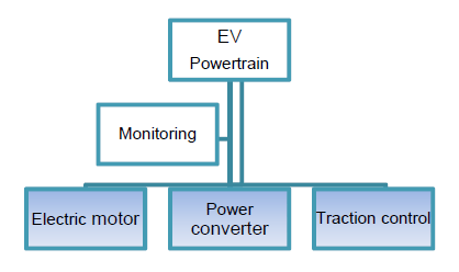
Many of these problems help to solve advanced and modern power electronics. Therefore, the Power Electronics systems has broadly entered Electromobility in the area that can be divided into three specific groups [1, 2, 3]: architecture of the power supply of charging station (in particular ultra-fast charging), battery charger systems themselves, and powertrain with AC motors. In this paper, due to the space limitation, we discuss only the powertrain systems for BEV. Typical components of a BEV powertrain are (Fig. 1): electric motor, power electronic system and traction control system. These components will be discussed below.
2. Electric traction motors
2.1 Types and characteristics
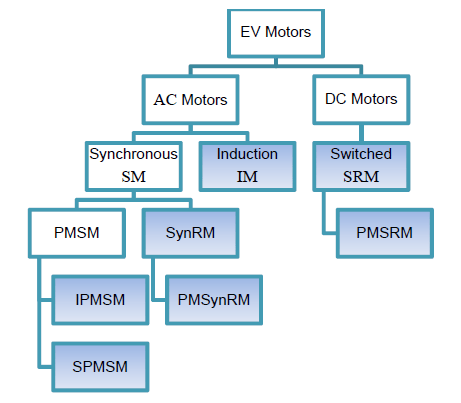
When analyzing the drives currently used (or will be used) in electric vehicles, particularly in BEV cars, one can conclude that they can be divided in three main groups: synchronous motors, induction motors, switched reluctance motors [1, 4, 11]. Synchronous and reluctance switched motors have various variants related to the construction and use of permanent magnets (Fig. 2).
Squirrel-cage induction motors (IM) (Fig. 3a) are machines with well-controlled technology and the introduction of rotors with copper casted cages increased their efficiency. Methods for determining the efficiency of induction motors are also developed and refined [5, 6, 7].
However, the IM have a lower power density (power/weight parameter) than the synchronous motors (SM) [2, 8].
Synchronous motors with permanent magnets placed on the surface of the rotor (SPMSM) (Fig. 3b) have high efficiency due to practically zero losses in the rotor and less mass. Motor design should take into account the heat dissipation from the motor, so that the magnets do not work at too high temperature as they may be exposed to demagnetisation.
Synchronous motors with permanent magnets placed inside the rotor (IPMSM) (Fig. 3c) are characterized by high efficiency and the possibility of flux weakening to a limited extent. As in SPMSM, proper cooling of the motor should be ensured so as not to demagnetize of magnets.
Synchronous reluctance motors (SynRM) (Fig. 3d)) operate on the principle of using the reluctance torque present in the machine due to the difference of conductivity in the d-axis and the q-axis. The greater their difference, the greater the torque of the motor. These are motors in which there are no permanent magnets. They have high efficiency, but a large mass and low power factor [9].
Synchronous reluctance motors with permanent magnets (PMSynRM) (Fig. 3e) differ from the previous ones by additionally using permanent magnets in the rotor. It definitely improves the motor parameters, particularly its power factor.

(a) squirrel-cage induction motor (IM), (b) surface PMSM, (c) internal PMSM, (d) Synchronous reluctance motors (SynRM), (e) Synchronous reluctance motors with permanent magnets (PMSynRM), (f) Switched reluctance motors (SRM), (g) Switched reluctance motors with permanent magnets (PMSRM)
Switched reluctance motors (SRM) (Fig. 3f) are characterized by a very simple construction. The concentrated windings used in them, compared to the distributed windings (usually used in alternating current motors) allow to reduce the amount of copper and the mass of the motor. SRMs have high efficiency, but very high torque ripple, high levels of noise and vibration. The advantage of them is the possibility of continuing work even when there is no power supply for one phase.
Switched reluctance motors with permanent magnets (PMSRM) (Fig. 3g) placed in the stator have better parameters than SRM, less torque ripple, less noise and vibrations. Since the magnets are placed in the stator, cooling is easy. Hybrid excitation motors (HEPMSRM) are the variant of these motors, in which there is an additional excitation winding in the stator in addition to the armature winding and permanent magnets [10, 11]. Control is more complicated, but the motor’s parameters are better.
2.2 Price of rare-earth magnets
Motors that use rare-earth magnets (Fig. 3 (b), (c), (e), (g)) may be uncompetitive in relation to motors without such magnets, because of the magnets price. Fig. 4 (based on [12]) shows the prices of this kind of magnets within last 10 years. Characteristics feature of the diagram is the fast growth in the period 2010-2013. It was caused by price increases by the monopolist (China). It was only the intervention of the World Trade Organization that caused a drop in prices. However, this problem can be repeated in the case of massive development of Electromobility and the related demand for rare-earth magnets.

How prices of rare-earth magnets affect the price of the motor can be seen in Fig. 5 [4]. In the critical year 2012, the share of rare-earth magnets in motor cost amounted to 53%, with their share in the motor weight of only 3%. After recalculation for 2018, the share of rare-earth magnets in the motor cost has dropped to 18%, but it is still high.
2,3 Requirements and rankings
The general requirements for electric machines intended for BEVs are much more demanding than those for industrial applications. The requirements are following [13]: high efficiency in a wide range of torque and speed, high reliability and robustness, high torque and power density, low mass, low cost, low acoustic noise and vibrations.
In early works (1991) [14] there were taken into consideration only three types of motors: induction (IM), permanent magnet (PMSM) and switched reluctance (SRM).
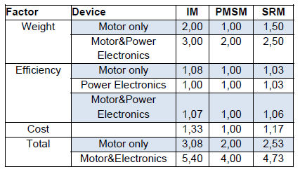
The type of motor to be used in BEVs is generally determined by three main factors: weight, efficiency and cost, and these are compared in the Table 1. In this ranking the best motor was IM in both individually and summed with power electronics.

Table 1. Comparison of different motor types (range of evaluation1–the worst, 3–the best)
In the following years there was development and improvement of the construction of motors designed for EV. This mainly applies to PMSM with variously placed magnets (IPMSM and SPMSM) [15-18], synchronous reluctance motors (SynRM) [9, 19] as well as with permanent magnets (PMSynRM) also referred to as Permanent Magnet Assisted Synchronous Reluctance Motor [9, 20–25]. The use of both rare earth and ferrite magnets is considered in PMSynRM constructions [23]. The construction with ferrite magnets is characterized by a much higher weight of magnets compared to rare earth (more than twice), but ferrite magnets are more than 100 times cheaper (!) in the considered motor design and their maximum working temperature is more than twice higher as rare-earths magnets. It should be noted that the other parameters of both motors are comparable.
Many developments are also apply to switched reluctance motors (SRM). Some constructions have parameters not much worse than SPMSM, for example [26]. There are also constructions (similar to PMSynRM) that contain permanent magnets PMSRM also referred to as Permanent Magnet Assisted Switched Reluctance Motor [9, 27-32].
Usually, the efficiency of the various types of motors used in the EV is shown as a map of efficiency (see Fig. 6) [33, 34]. It depends on the speed and torque. Depending on the required parameters, different types of motors can work in different operating ranges. Therefore, the entire drive system should be properly designed depending on the motor used.
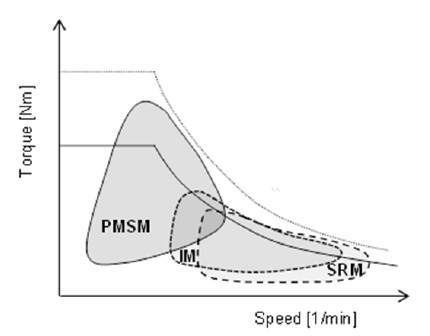
Detailed calculations of the three types of motors were carried out in [15]. Fig. 7 shows their characteristics and they are generally consistent with the characteristics shown in Fig. 6.

On the basis [15, 9, 35, 36], individual types of motors were evaluated (Table 2). The most points were received by PMSRM and PMSynR. It should be emphasized that these are motors that are currently undergoing intensive research and have a great future potential. It seems that they will dominate EV drives in the near future. There is a certain margin of uncertainty related to technology and practical testing, but rather there should be no problems with it.
Table 3 presents AC motors used in EV, taking into account additionally such parameters as power factor and field weakening ability. Formulas for torque and losses in windings were also shown. There are visible in IM the losses occurring in the winding of the rotor, which are not present in other types of motors. Hence, the lower efficiency of the IM. The PMSynRM engine received the most points, which is consistent with the results from Table 2.
Table 2. Motors for electric cars (range of evaluation 1–the worst, 3–the best)

Table 3. AC motors with three-phase stator windings and different rotors
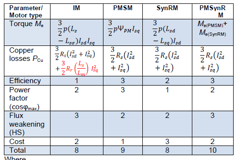
Where
p number of pole-pairs
Ls stator phase self-inductance
Lsσ stator phase leakage inductance
Isd d-axis component of stator current
Isq q-axis component of stator current
ΨPM permanent magnet flux linkage
Lsd d-axis stator phase self-inductance
Lsq q-axis stator phase self-inductance
Me(PMSM) + Me(SynRM) electromagnetic torque
Rs stator phase resistance
Rr rotor phase resistance
Lm main phase inductance
3. Power electronic systems
Basic requirements for power electronic systems used in BEV (and HEV) can be formulated as follows:
• bidirectional power flow for motor and regenerative operation,
• high efficiency and power density for minimizing dimension and weight,
• high capacity (continuous, overvoltage, overload),
• ruggedness against vibration, shock, and extreme temperatures,
• compact design and high reliability,
• low price (for given output) and low EMI.

The example of typical costs distribution of traction inverter is presented in Fig. 8, which shows clearly that the most expensive elements are power modules, gate drivers and DC bus capacitors. Therefore, the type of power modules and topology used have the decisive influence on the inverter’s cost. So the problem of development of traction inverters will be discussed below in two main parts: components and topologies.
3.1 Power electronic components
The fundamental progress observed recently in the development of traction converters is due to new semiconductor materials, component integration, better cooling, higher packing, cost reduction and increased reliability. It is strongly related to fast development of new power semiconductor devices based on wide band-gap energy (WBG) materials as silicon carbide (SiC) and nitride gal (GaN) which over classical silicon (Si) devices have following important advantages:
• higher voltage blocking capability,
• faster switching speed,
• higher temperature range,
• higher thermal conductivity,
• low internal resistance (100 times as Si),
• reduced dimension of devices,
• exceptional radiation hardness.
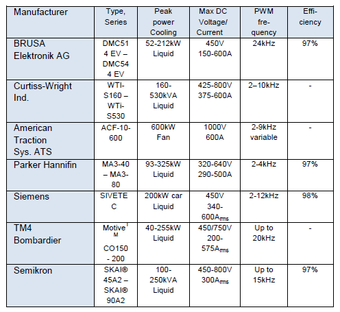
These important properties have decided that SiC becomes de facto semiconductor technology for modern BEV (and HEV). Table 4 presents some selected power modules produced by leading world manufactures dedicated for Electromobility [38-44]. Currently, most manufacturers still offer Si power modules, however with a clearly increasing number of SiC devices.
Table 4. Power modules dedicated for electric cars

Last investigations [45, 46] shows that state-of-the-art available high power SiC MOSFET (Cree/Wolfspeed: CAS300M17BM2, 1700V/325A) modules in comparison with Si IGBT (Infineon: FF200R17KE3, 1700V/310A) modules have only ¼ switching losses giving in 2-Level 100kW converter 96,2% efficiency at 80kHz switching frequency, whereas inverter with Si IGBT achieves similar efficiency already at 10kHz (Fig. 9). However, the SiC MOSFET modules’ maximum allowed gate negative voltage (–10V) is lower than that of Si IGBT (–20V) and the gate threshold voltage is smaller (2.3V versus 5.8V). Thus, the risk of damage due to the crosstalk1 effect is in SiC MOSFET modules higher than in Si IGBT modules. Therefore, the gate drivers for SiC MOSFET modules must be carefully designed [45].
1 The induced negative gate voltage due to complementary device turn-off, also known as “parasitic gate turn-ON”

However, the efficiency of power electronics systems does not only depend on the innovation in the power and control circuits, but requires also continuous improvements in the technology of components assembling on a compact package creating reliable and durable systems that are resistant to vibration and heat. An important element of power modules having an impact on the improvement of high voltage insulation, thermal management, partial discharging and EMI is the type of substrate (it constitutes the backbone of power electronics modules) material. The ceramic materials used in the power modules compared to organic ones provide: excellent electrical insulation, very good thermal conductivity and similar to semiconductor materials thermal expansion coefficient. In addition, most of the suppliers (pioneered by Hitachi [44]) have achieved a significant reduction in the size and weight of the inverter by developing a double-sided cooling technology that uses liquid or air cooling to allow direct cooling of the high voltage module.
Although SiC and GaN converters showed higher efficiency than based on Si, reliability concerns still limit the development of the WBG market. Obtaining higher reliability requires a better understanding of degradation and failure mechanisms in difficult BEV operation conditions (i.e. stresses such as high dv/dt and high temperatures, vibrations) yet long-term research and testing are needed.
3.2 Topologies
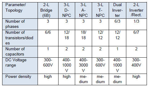
Basic topologies of low-voltage converters used in Electromobility are shown in Fig. 10 (Table 5). With regard to traction drives, the two-level bridge (2L-6B) converter topology dominates (Fig. 10a) because is simple and inexpensive standard solution. However, three-level (Fig. 10b-d) topologies have a great potential to improve twolevel converter parameters by reduction of switching losses and volume of passive components as well as better quality of the output voltage [47, 48].
The 3-level topologies (Fig. 10b-d) apply split-capacitor connection at the DC-link, therefore, contrarily to 2-level topology, the power switches are exposed only to half of DC-link voltage. Thus, the higher number but cheaper lower rated voltage switches can be used for converter construction. Moreover, the use of additional switches allows the application of various modulation options (several discontinuous and modified PWM [47, 48]), so that individual switches are switched on and off less often, which leads to reduction of switching stress and losses. A single leg of 3-level converter generates three different values output voltages: -Vdc/2, 0, Vdc/2 denoted as [N,O,P], respectively. So, 27 different vectors can be generated on the outputs of every leg vabc = [va, vb, vc]. All three topologies have common problem of DC-link capacitor voltage balancing.
Table 5. Three-phase converter topologies for electric cars
3L-D-NPC: One of the most popular 3-level topologies is the D-NPC converter (Fig. 10b) proposed in 1981 [49]. Each converter leg consists of four transistors with four reverse diodes and two clamping diodes. In every of N,O,P switching states two devices are connected in series which makes it possible to split the necessary blocking voltage and thus reducing the switching stress and losses. Therefore, the switching frequency of the D-NPC can be increased without much reduction of efficiency. However, when comparing to 2L converter, the D-NPC has higher number of semiconductor devices and requires 6 additional gate drivers. Also, there is an uneven loss distribution among switches depending on modulation index. The DNPC is widely applied in medium-voltage applications (wind energy systems, train traction drives).

(a) 2-Level bridge 2L, (b) 3-Level Diode Neutral Clamped Converter DNPC, (c) 3-Level Active Neutral Point Clamped Converter A-NPC (d) 3-level Transistor Neutral Point Clamped Converter T-NPC (also known as T-Type Converter).

3L-A-NPC: The active NPC topology (Fig. 10c) has been proposed in 2005 [50] with the goal to compensate the unequal loss distribution of the classical D-NPC converter. The modification consists in adding power transistors reverse-parallel connected to the clamping diodes to obtain active switches (Fig. 10c). These active switches create additional current paths for the DC-link midpoint enabling equalization of currents and switching losses over switches. Additionally, the extra switches gives more flexibility for balancing of DC-link midpoint voltage and also enable their use to increase fault-tolerant operation [51]. However, more number of switches introduces more losses and as result reducing the overall efficiency of converter.
3L-T-NPC: The transistor NPC (T-type) is interesting topology that in an elegant way combines the advantages of 2- level: low conduction losses, small number of components and simple principle of operation with advantages of 3-level converters: low switching losses and better output voltage quality [52-55]. It consist of six switches 2-level converter with additional three active lower voltage rated bidirectional switches connected every leg to the DC-link midpoint (Fig. 10d). So, this topology eliminates 6 (clamping) diodes from the basic D-NPC converter and provide 3-level voltage waveform despite of keeping 2-level topology. Thanks to use of lower voltage rating for bidirectional switches both the conduction and switching losses can be reduced [54, 55]. Additionally, the 3L-T-NPC converter has higher reliability in case of switch faults [56]. The view and typical waveforms in the 30kVA 3L-T-NPC prototype SiC converter build in Electrotechnical Institute (IEL), Warsaw are shown in Fig. 11 [57-59].
Dual inverter: To increase the power of traction drives, also dual topologies are used (Fig. 12). Both presented topologies parallel and cascaded has the same inverter configuration (2-level or 3-level), but differ only in motor connection. The parallel topology (Fig. 12a) allows to increase power by extend current capability using two converters connected to two sets of three-phase (30 degree phase shifted) or six-phase isolated motor winding. The dual cascade topology allows increasing the output power by doubling the output voltage (Fig. 12b) using two inverters connected in series with motor phase winding. The modulation techniques used in parallel and cascade topology are different. As result of using appropriate phase shift of carrier signal in the modulator, the DC-link capacitor current ripple, and thus the DC capacitor volume, are about 30% lower in cascade than parallel connection [60].

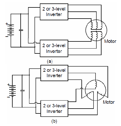
Integrated inverter/rectifier (motor/charger): A special group creates topologies, which allow using the same converter and motor for driving and on-board battery charging operation. As result the size and weight of chargers can be significantly reduced. Many versions of such integrated systems have been developed [61-69]. In Fig. 13 two examples of non-isolated integrated topologies are shown. The topology presented in Fig. 13a, in battery charging mode, use two additional switches K1 and K2 for inverter reconfiguration into single-phase AC-DC active rectifier and the motor winding as grid-side inductors [63]. In contrast, Figure 13b shows the topology in which the inverter operates in the charging mode as single-phase DCDC converter (only lower switches of the three-phase bridge are switched creating with motor winding the DC-DC interleaved converter). In this case the neutral point of the motor has to be available. There are also more complicated two-stage [69] and isolated topologies [61].
Losses comparison: The losses of electric drive consist mainly of inverter and machine losses. The Figure 14 shows a losses comparison of an induction motor drive supplied from 2-Level 6B and 3-Level T-NPC inverters. The losses of the inverters include only the dominant switching losses (conduction loss of power semiconductors are omitted), while losses in the induction machine take into account only the losses caused by harmonics under the PWM voltage supply. The switching losses of 3-Level in comparison with 2-Level topology is reduced mainly thanks to halved commutation voltage and better loss distribution over individual semiconductors [54]. The machine harmonic losses are difficult to calculate and measure because they depend on several construction-specific parameters as winding type, slotting, lamination, etc. In the range of higher switching frequency (≥ 10kHz) only eddy current iron losses are taken into account while harmonics ohmic losses are neglected. Under this assumption the approximated harmonic losses can be expressed as proportional to square of voltage ripple [54] Phar = KeddyΔV2rms , where: Keddy – machine loss constant in [W/V2], Vrms– machine phase voltage in [V]. Therefore, the observed in Fig. 14 reduction of harmonic losses for 3-Level inverter is independent of machine power rating, the DC-link voltage and switching frequency giving a simple first approximation.

Table 6. Traction inverters for electric cars
When considering the entire drive system, we see that with the increase of the switching frequency, the losses of the machine decrease and the inverter grows. The minimum total losses are in the range of relatively low switching frequencies ca 6 – 9kHz. Although the presented dependencies are considered for two specific types of inverters, they nevertheless characterize well tendencies to optimize the efficiency of traction drives. They clearly show that the high switching frequencies do not reduce total losses, therefore they should be used only to reduce the weight and volume of the inverter as well as acoustic noise and to improve the dynamic properties.
Selected examples of traction inverters offered by global manufacturers (Table 6) cover almost exclusively 2-Level topologies confirming their dominant role [70-77].

4. Traction control systems
The basic requirements for control systems of electric car drives can be formulated as follows:
• Four quadrant (driving and braking) operation,
• Wide speed adjustment range at constant torque and constant power regions,
• Minimization of inverter and motor losses,
• Maximum utilization of available battery DC voltage,
• High reliability and low costs.
Currently, in traction drives due to high reliability (no mechanical commutator), AC motors are used which control methods more complicated compared to DC motors. Generally, the power of the electric motor can be expressed as: P = Me Ω = k V4/3 Ω, where: Me – electromagnetic torque, Ω – angular speed, and V – motor volume (dimensions and weight). Therefore, in order to maintain small dimensions, power is increased by increasing the motor speed. Desirable static characteristics representing, on the example of a squirrel-cage induction motor, ranges of angular speed regulation of the AC traction drive are shown in Fig. 16. The IM can operates in basic speed range at constant torque and high speed range at constant power and constant slip regions whereas PMSM operates only in basic constant torque and high speed constant power region. This form of static characteristics of AC motors is compatible with the requirements of traction drive in which the highest torque is required during start-up and then reduces with increasing speed.
Basically, the traction control system consist of torque and flux loops and optionally can include speed control loop which is added as outer loop for torque controller.

4.1. Torque and flux control methods
Vector Control: Among the control methods of traction drives, vector control methods predominate, which provide excellent dynamic properties and decoupled (independent) torque and flux control. Once the fast flux and torque control is achieved, the outer loops as speed, position control can be easy added. These methods are used in both IM and PMSM drives and are collected in Table 7. Table 7. Torque and flux control systems
Figure 18 shows a block diagram and a simplified space vector diagram of the popular Field Oriented Control (FOC) method, which includes the following current regulation loops: Isd – proportional to the flux, Isq – proportional to the electromagnetic torque, and space vector pulse width modulator (SVM) controlling the transistors of the inverter supplying the motor.
The presence of the SVM modulator is important as it ensures the operation of the inverter with a constant switching frequency and low switching losses, especially in the modulator version realizing two-phase modulation (ie one of the phases is not switched) so-called flap top modulation [47, 48]. In addition, the SVM modulator also provides linearization of the inverter control, what together with the coordinate transformations (stationary to synchronous α-β/d-q and inverse d-q/α-β) allows the use of PI linear current regulators. This also applies to the direct torque control with space vector modulation (DTC-SVM) method (see Table 7) where instead of current PI the torque and flux PI regulators are used [78]. Additionally, the SVM helps in analyze and reduction of EMI generated by drive system [79].

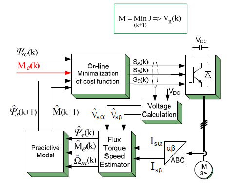
Model Predictive Control: Recently, thanks to the rapid development of the computing power of DSP signal processors and FPGA circuits, the model predictive control methods (MPC) are intensively developed [80-84]. An example of model predictive torque and flux control (MPCPTC) scheme is shown in Fig. 18.
The system contains blocks typical for MPC: flux, torque and speed estimators, predictive discrete model of control plant (motor + inverter),and in every sampling k calculation of cost function minimum. Therefore, the system’s properties depend on the accuracy of the predictive model of the control plant and the formulation of the cost function, which next to the error between measured and predicted values of controlled variable can also contain additional specific components such as the limit of inverter switching number, range of field weakening, losses, thermal models, etc.
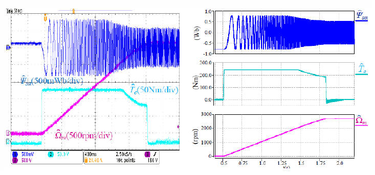
This together with the lack of restrictions on the linearity of the control plant gives a very flexible control in which the process of selecting linear regulators has been replaced by the on-line optimization process. The MPC system can work in the range of over-modulation including square operation, which ensures maximum utilization of the battery DC voltage supplying the inverter. The perfect dynamic behavior of the MPC controlled IM traction drive is presented in oscillogram of Fig. 19 [80, 81]. The disadvantage of predictive methods is the required large number of on-line calculations, however, algorithms that allow their significant reduction are intensively developed [80].
5. Summary and conclusion
• The current development of electric motors for BEV powertrain shows the following trends: – increase efficiency while keeping the motor weight, – limiting the use of rare-earth magnets and replacing them with permanent ferrite magnets. The IM lost its dominant position in EV drives over thirty years and was substituted by PMSM. It is expected that in the future will probably be replaced by PMSynRM and PMSRM Motor.
• Topologies of traction converters reward simple and proven two- and three-level solutions. Lately, due to high efficiency and increased reliability, interest in three-level T-type converters (T-NPC) is increasing.
• The essential development of the converters is based on the use of SiC power modules, improvement of cooling methods due to double-sided heat removal from the structure of the device (Hitachi) and reduction of passive elements.
• To minimize the losses of the entire electric vehicle drive, it is not necessary to increase the inverter switching frequency. However, it is required for converter size and weight reduction as well as minimization of acoustic noise and mechanical vibrations.
• For traction control currently the vector control is dominating, however modern predictive methods with a model that uses on-line optimization algorithms have great potential to replace them.
• To ensure the massive development of Electromobility – regardless of providing excellent traction parameters – electric drive costs are expected to be significantly reduced by 2025, including e-motors 10% and inverters 25%. This requires a lot of effort in the development of new materials, optimized constructions, thermal management as well as control and monitoring methods. That is why it requires engineers to constantly carry out research and design works.
• It is expected that power electronic systems and electric machines will be the subject of extensive research and multi-criteria optimization of parameters in connection with the massive development of Electromobility.
REFERENCES
[1] Grunditz E.A., Thiringer T., Performance Analysis of Current BEVs Based on a Comprehensive Review of Specifications, IEEE Transactions on Transportation Electrification, 2 (2016) No. 3, 270-289
[2] Rajashekara K., “Present Status and Future Trends in Electric Vehicle Propulsion Technologies”, IEEE Journal of Emerging and Selected Topics in Power Electronics, Vol. 1, (2013), No.1, 3-9
[3] Kazmierkowski M.P. and Zymmer K., “Power electronic architecture of supply systems for electric vehicle charging”, Proceedings of Electrotechnical Institute, 65 (2018), issue 278, 7-20
[4] Miller J. M., Electric Motor R&D, https://www.energy.gov/sites/prod/files/2014/03/f13/ape051_mil ler_2013_o.pdf
[5] Dabala K., Hybrid Method of Induction Motors Efficiency Determination, Proceedings of Electrotechnical Institute, 271 (2015) (in Polish), 145 pg
[6] Dabala K., Selected Elements of a New Method of Induction Motors Efficiency Determination, Bull. Pol. Ac.: Tech., Vol. 64, 2 (2016), 307-313
[7] Sridharan S., Krein P.T., Minimization of System-Level Losses in VSI-Based Induction Motor Drives: Offline Strategies, IEEE Transactions on Industry Applications, 53 (2017) No. 2, 1096-1105
[8] Buyukdegirmenci V.T., Bazzi A.M., Krein P.T., Evaluation of Induction and Permanent-Magnet Synchronous Machines Using Drive-Cycle Energy and Loss Minimization in Traction Applications, IEEE Transactions on Industry Applications, 50 (2014) No. 1, 395-403
[9] Boldea I., Tutelea L., Reluctance Electric Machines: Design and Control, (2019) CRC Press, ISBN: 978-1-4987-8233-3
[10] Ding W., Li S., Maximum Ratio of Torque to Copper Loss Control for Hybrid Excited Flux-Switching Machine in Whole Speed Range, IEEE Transactions on Industrial Electronics, 2 (2019), 932-943
[11] Ding W., Yang S., Hu Y., Performance Improvement for Segmented-Stator Hybrid-Excitation SRM Drives Using an Improved Asymmetric Half-Bridge Converter, IEEE Transactions on Industrial Electronics, 2 (2019), 898-909
[12] https://www.reuters.com/article/us-metals-autos-neodymiumanalysis/teslas-electric-motor-shift-to-spur-demand-for-rareearth-neodymium-idUSKCN1GO28I
[13] Chau K. T., Li W., Overview of electric machines for electric/hybrid vehicles, https://core.ac.uk/download/pdf/38055214.pdf
[14] West J. G. W., DC, Induction, Reluctance and PM Motors for Electric Vehicles, IEE Colloquium on ”Motors and drive systems for battery-powered propulsion”, 15th April 1991, 1-11
[15] Yang Z., Shang F., Brown I. P., Krishnamurthy M., Comparative Study of Interior Permanent Magnet, Induction, and Switched Reluctance Motor Drives for EV and HEV Applications, IEEE Transctions on Transportation Electrification, 3 (2015), 245-254
[16] Piotuch R., Pałka R.: „Comparison of Two Synchronous Motors with Interior Magnets”, Przegląd Elektrotechniczny, Vol. 93 (2017) No. 2, 1-4: DOI:10.15199/48.2017.02.01
[17] Szczypior J., Jakubowski R., Biernat A., Rzeszowski M.: Project, design and tests of in-wheel outer-rotor PMSM for electric car application. Part 1” Przegląd Elektrotechniczny, Vol.93 (2017) No. 2, 131-137; DOI:10.15199/48.2017.02.30
[18] Szczypior J., Jakubowski R., Biernat A., Rzeszowski M.: Project, design and tests of in-wheel outer-rotor PMSM for electric car application. Part 2”, Przegląd Elektrotechniczny, vol. 93 (2017) No. 2, 138-146; DOI:10.15199/48.2017.02.31
[19] Siadatan A., Adab M.K., Kashian, H., Compare Motors of Toyota Prius and Synchronous Reluctance for Using in Electric Vehicle and Hybrid Electric Vehicle, 2017 IEEE Electrical Power and Energy Conf. (EPEC), 1-6
[20] Nagarajan V.S., Kamaraj V., Sivaramakrishnan S., Geometrical sensitivity analysis based on design optimization and multiphysics analysis of PM assisted synchronous reluctance motor, Bull. Pol. Ac.: Tech., DOI: 10.24425/bpas.2019.127345
[21] Lingyujin G., Xiaoyong Z., Wenye W., Fangjie L., Zixuan X., Design and Comparison of Two Non-Rare-Earth Permanent Magnet Synchronous Reluctance Motors for EV Applications, IEEE (2017), DOI: 10.1109/ICEMS.2017.8056171
[22] Ibrahim M. N. F., Rashad E., Sergeant P., Performance Comparison of Conventional Synchronous Reluctance Machines and PM-Assisted Types with Combined Star–Delta Winding, Energies, 10 (2017), 2-18
[23] De Gennaro M., et al, Designing, prototyping and testing of a ferrite permanent magnet assisted synchronous reluctance machine for hybrid and electric vehicles applications, Sustainable Energy Technologies and Assessments, 31 (2019), 86-101
[24] Xiping l., Ya L., Zhangqi L., Tao Ling., Zhenhua L., Optimized design of a high-power-density PM-assisted synchronous reluctance machine with ferrite magnets for electric vehicles, Archives of Electrical Engineering, 2 (2017), 270-293
[25] Bianchi N., Fornasiero E., Carraro E., Bolognani S., Castiello M., Electric Vehicle Traction based on a PM Assisted Synchronous Reluctance Motor, 2014 IEEE International Electric Vehicle Conference (IEVC), 1-6
[26] Zhu J., Cheng K. W. E., Xue X., Comparison Study of rareearth-free motors with permanent magnet motors in EV applications, 7th International Conference on Power Electronics Systems and Applications – Smart Mobility, Power Transfer & Security (PESA), (2017), DOI:10.1109/pesa.2017.8277735, 1-5
[27] Sun X., Xue Z., Han S, Chen L., Xu X., Yang Z., Comparative study of fault-tolerant performance of a segmented rotor SRM and a conventional SRM, Bull. Pol. Ac.: Tech., 65 (2017) No. 3, 375-381 DOI: 10.1515/bpasts-2017-0042
[28] Nakamura K., Murota K., Ichniokura O., Characteristics of a Novel Switched Reluctance Motor having Permanent Magnets between the Stator Pole-Tips, European Conference on Power Electronics and Applications, (2007)
[29] Lobo N. S., Doubly-Salient Permanent Magnet Flux-Reversal-Free-Stator Switched Reluctance Machines, PhD, (2011), 1-149 pg
[30] Ullah S., A Magnet assisted segmental rotor switched reluctance machine suitable for fault tolerant aerospace applications, PhD, (2016), 1-180 pg
[31] Hwang H., Hur J., Lee Ch., Novel Permanent-Magnet-Assisted Switched Reluctance Motor (I): Concept, Design, and Analysis, International Conference on Electrical Machines and Systems, (2013)
[32] Bouiabady M. M., Aliabad A. D., Amiri E., Switched Reluctance Motor Topologies: A Comprehensive Review, Intech, (2017)
[33] Finken T., Felden M., Hameyer K., Comparison and design of different electrical machine types regarding their applicability in hybrid electrical vehicles, Proceedings of the 2008 International Conference on Electrical Machines, Paper ID 988
[34] Shah S. B., Silwal B., Lehikoinen A., Efficiency of an Electrical Machine in Electric Vehicle Application, Journal of the Institute of Engineering, 11(1) (2015), 20-29
[35] Jacobs S., Vandenbossche L. and Attrazic E., How electrical steel optimizes traction electric Machine Design. A serviceable contribution to electric vehicles. IEEE Electrification Magazine, 7 (2019), No. 3, 39-48.
[36] EL-Refaie A. M., Toward a sustainable More electrified Future, The role of electrical machines and drives, IEEE Electrification Magazine, 7 (2019), No. 3, 49 – 59.
[37] https://www.psma.com/sites/default/files/uploads/tech-forumstransportation-power-electronics/presentations/is116-electricdrive-technologies-research-roadmap-update.pdf
[38] https://www.infineon.com/dgdl/Infineon-Hybrid+electric+and+electric+cars-ABR-v03_00-EN.pdf?fileId=5546d4625d5945ed015dc81f427b36a6
[39] https://www.rohm.com/sic/full-sic-power-modules
[40] http://files.danfoss.com/download/Drives/HiRes_DKSPPB434A102_Danfoss_DCM1000.pdf
[41] Shajarati O., Olesen K., Apfel N., Beck M., “DCM™1000 Designed to meet the future demand of Electric Vehicle Drive Trains”, Bodo’s Power Systems, March, (2018), pp. 3—35.
[42] http://samochodyelektryczne.org/danfoss_przygotowuje_sie_na_elektryfikacje_poprzez_przejecie_visedo.htm
[43] http://www.mitsubishielectric.com/semiconductors/application/automobile/index.html
[44] https://eepower.com/semiconductors/hitachi-suijin-seriespower-modules-electric-vehicles-hitachi-europe-limited-1134
[45] Zhang L., Yuan X., Wu X., Shi C., Zhang J., Zhang Y., Performance Evaluation of High-Power SiC MOSFET Modules in Comparison to Si IGBT Modules, IEEE Transactions on Power Electronics, 34, (2018), No. 2, 1181 – 1196;
[46] Kim H., Chen H., Zhu J., Maksimovic D. and Erickson R, “Impact of 1.2kV SiC-MOSFET EV Traction Inverter On Urban Driving”, https://ecee.colorado.edu/~rwe/papers/WiPDA16.pdf
[47] Zhao D., Hari V.S.S.P.K., Narayanan G. and Ayyanar R., “Space-Vector-Based Hybrid Pulsewidth Modulation Techniques for Reduced Harmonic Distortion and Switching Loss,” in IEEE Transactions on Power Electronics, vol. 25, (2010) No. 3, 760-774
[48] Wu Y., Shafi M.A., Knight A.M. and McMahon R.A., “Comparison of the Effects of Continuous and Discontinuous PWM Schemes on Power Losses of Voltage-Sourced Inverters for Induction Motor Drives,” in IEEE Transactions on Power Electronics, vol. 26 (2011) No. 1, 182-191
[49] Nabae A., Takahashi I., Akagi H., A New Neutral-Point-Clamped PWM Inverter, IEEE Transactions on Industry Applications, 17(1981) No. 5, 518-523
[50] Bruckner T., Bernet S., Guldner H., The Active NPC Converter and its Loss-Balancing Control, IEEE Transactions on Industrial Electronics, 52 (2005) No. 3, 855-868
[51] Brueske S, Fuchs F.W., “Efficiency Optimisation of a Neutral Point Clamped Inverter for Electric Vehicles by Means of a Variable DC Input Voltage and Different Power Semiconductors”, in Proc. of 16th European Conference on Power Electronics and Applications, (2014),1-10
[52] Holtz J., “Selbstgefuhrte Wechselrichter mit treppenformiger Ausgangsspannung fur grose Leistung und hohe Frequenz,” Siemens Forschungs-und Entwicklungsberichte, vol. 6 (1977) No. 3, 164–171
[53] Dixon J. and Morán L., High-level multistep inverter optimization using a minimum number of power transistors, IEEE Trans. Power Electron.,vol. 21 ( 2006) No. 2, 330–337
[54] Schweizer M. Friedli T.,Kolar J.W. Comparative Evaluation of Advanced Three-Phase Three-Level Inverter/Converter Topologies Against Two-Level Systems, IEEE Transactions on Industrial Electronics, Vol. 60, No. 12, 5515 – 5527; DOI: 10.1109/TIE.2012.2233698
[55] Schweizer M. and Kolar J.W., „Design and Implementation of a Highly Efficient Three-Level T-Type Converter for Low-Voltage Applications”, IEEE Transactions on Power Electronics, Vol. 28 (2013), No. 2,899 – 907; DOI: 10.1109/TPEL.2012.2203151
[56] Wang Z., Wang X., Cheng M., Hu Y., Comprehensive Investigation on Remedial Operation of Switch Faults for Dual Three-Phase PMSM Drives Fed by T-3L Inverters, IEEE Transactions on Industrial Electronics,65 (2018), No. 6, 4574 – 4587
[57] Rabkowski J., Sak T., Strzelecki R., M. Grabarek M., SiCbased T-type modules for multi-pulse inverter with coupled inductors, 11th IEEE International Conference CPEPOWERENG), (2017), 568 – 572
[58] Rąbkowski J., Piasecki Sz., Kopacz R., An Extended T-type (eT) inverter based on SiC Power Devices, EPE-ECCE Europe Conference, 2018, P.1-P.10
[59] Rąbkowski J., Kopacz R., Extended T-type inverter, Power Electronics and Drives, 38 (2018) No. 1, 55-64
[60] Chen L., Ge B., High Power Traction Inverter Design and Comparison for Electric Vehicles, 2018 IEEE Transportation Electrification Conference and Expo (ITEC), 583-588
[61] Sakr N., Sadarnac D., and Gascher A., “A review of on-board integrated chargers for electric vehicles,” presented at EPE Energy Convers. Congr. Expo. Europe, Lappeenranta, Finland, (2014) P.1-P.10
[62] Haghbin S., Lundmark S., Alaküla M., and Carlson O., “Grid-Connected Integrated Battery Chargers in Vehicle Applications: Review and New Solution”, IEEE Transactions on Industrial Electronics, Vol. 60 (2013) No. 2, 459-473.
[63] Cocconi A.G. and Calif G., “Combined motor drive and battery recharge system,” (1995) U.S. Patent 5 341 075
[64] Subotic I., Bodo N., and Levi E., “An EV drive-train with integrated fast charging capability,” IEEE Transactions. on Power Electronics., vol. 31 (2016) no. 2, 1461–1471
[65] Subotic I., Bodo N., and Levi E.: “Single-Phase On-Board Integrated Battery Chargers for EVs Based on Multiphase Machines”, IEEE Transactions on Power Electronics, Vol. 31, (2016) No. 9, 6511-6523
[66] Woo D., Joo D., and Lee B., “On the feasibility of integrated battery charger utilizing traction motor and inverter in plug-in hybrid electric vehicle,” IEEE Transactions on Power Electronics., vol. 30, (2015) No. 12, 7270–7281
[67] Solero L., “Nonconventional on-board charger for electric vehicle propulsion batteries,” IEEE Transactions on Vehicular. Technology., vol. 50, (2001) No. 1, 144–149
[68] Moradewicz A.J. “On/Off – board chargers for electric vehicles” Przegląd Elektrotechniczny, Vol. 95 (2019) No. 2, 136-139; DOI:10.15199/48.2019.02.30
[69] Shi Ch., Khaligh A., A Two-Stage Three-Phase Integrated Charger for Electric Vehicles With Dual Cascaded Control Strategy, IEEE Journal of Emerging and Selected Topics in Power Electronics, Vol. 6, (2018), No. 2, 898-908
[70] https://www.brusa.biz/nc/en/products.html
[71] https://www.semikron.com/products/productclasses/systems/detail/skai-90-a2-gd06-wdi-14282033.html
[72] https://www.cw-industrialgroup.com/Products/Motor-Controllers/Motor-Controllers-Hybrid-Vehicles/Traction-Inverters
[73] Yamada H., Saito R., Matsunobu Y., Ishizu T., Miyazaki T., “Components and Systems for Electric Vehicles (HEVs/EVs), January 2018, Hitachi review, January 2018; http://www.hitachi.com/rev/archive/2018/r2018_01/pdf/P103-109_R1b02.pdf
[74] http://www.americantraction.com/wpcontent/uploads/2015/02/ACF-10-600.pdf
[75] http://www.parker.com/Literature/Electromechanical%20Europe/Literature/192_300100_Mobile_Inverters_and_Motors.pdf
[76] https://w3.siemens.com/topics/global/en/electromobility/pages/powertrain-ecar.aspx
[77] https://www.tm4.com/
[78] Stando D., Kaźmierkowski M.P., Orłowska-Kowalska T., Control of the induction motor by the modified DTC-SVM method over a wide speed range for traction vehicles (in Polish), Przegląd Elektrotechniczny, R. 88 (2012) Nr 11a, 8-11
[79] Turzyński M., Induction machine behavioural modelling for prediction of EMI propagation, Bull. Pol. Ac.: Tech., 247-254; DOI: 10.1515/bpasts-2017-0028
[80] Stando D., Predictive Control of 3-Level Inverter-Fed Sensorless Induction Motor Drive, PhD Thesis, Warsaw University of Technology, Faculty of Electrical Engineering, 2018
[81] Stando D. and Kazmierkowski M.P., “Optimal Switching Sequence – Model Predictive Flux Control of Three-Level Inverted-Fed Induction Motor Drive”, Proceedings of Electrotechnical Institute, 65 (2018), issue 280, 25-37
[82] Falkowski P., Predykcyjna regulacja momentu i strumienia silnika indukcyjnego – dobór współczynnika wagowego, Przegląd Elektrotechniczny, Vol. 94 (2018) no. 3, 30-37
[83] Urbanski K., A new sensorless speed control structure for PMSM using reference model, Bull. Pol. Ac.: Tech., 489-496; DOI: 10.1515/bpasts-2017-0054
[84] Wróbel K.: Predictive speed control with finite control set of induction motor – comparison study”, Przegląd Elektrotechniczny, vol. 93, (2017) No. 2, 255-258; DOI:10.15199/48.2017.02.56
Authors: dr hab. inż. Konrad Dąbała, Sieć Badawcza Łukasiewicz Instytut Elektrotechniki, Zakład Napędów Elektrycznych, ul. Pożaryskiego 28, 04-703 Warszawa, E-mail: k.dabala@iel.waw.pl; prof. dr hab. inż. Marian P. Kaźmierkowski, Sieć Badawcza Łukasiewicz Instytut Elektrotechniki, Zakład Napędów Elektrycznych, ul. Pożaryskiego 28, 04-703 Warszawa; Politechnika Warszawska, Wydział Elektryczny, Zakład Elektroniki Przemysłowej, Plac Politechniki 1, 00-661 Warszawa, E-mail: mpk@isep.pw.edu.pl.
Source & Publisher Item Identifier: PRZEGLĄD ELEKTROTECHNICZNY, ISSN 0033-2097, R. 95 NR 9/2019. doi:10.15199/48.2019.09.01
