Published by Saheed Lekan GBADAMOSI1, Nnamdi NWULU1, O.M. BABATUNDE2,
Dept. of Electrical & Electronics Engineering Science, University of Johannesburg, South Africa (1), University of Lagos, Nigeria (2)
Abstract. This paper presents a modelling and simulation approach using the Electrical Transient Analyzer Program software to evaluate the magnitude and effects of harmonics from varying RES into the transmission system. An analytical technique was developed to estimate and quantify the harmonic power flow and losses amplification on the transmission lines. The efficiency of the proposed approach is implemented on nondistorted Garver’s 6 bus and IEEE 24 bus test systems. The developed technique can quantitatively estimate harmonic contributions from RES.
Streszczenie.. W artykule przedstawiono podejście do modelowania i symulacji przy użyciu programu Electrical Transient Analyzer – programu do oceny wielkości i skutków harmonicznych ze zmieniających się źródeł odnawialnych do systemu przesyłowego. Opracowano technikę analityczną do szacowania i określania ilościowego przepływu mocy harmonicznych i strat w liniach przesyłowych. Efektywność proponowanego podejścia jest implementowana w 6-szynowych systemach Garvera i IEEE 24. (Oszacowanie harmonicznych w systemie przesyłowym z dużej skali odnawialnymi źródłami energii)
Keywords: Generation, Harmonics, Power loss, Renewable energy sources, Transmission.
Słowa kluczowe: żródła odnawialne, systemy przesyłowe, zawartość harmonicznych.
Introduction
As the utilization of renewable energy sources are actively promoted with many countries of the world meeting their energy demand through the use of RES. In order to accommodate these sources, the transmission network is faced with various challenges such as power quality, system reliability, and frequency and voltage imbalance which has adverse effects on the power system operation. In modern power system, the mature RES technologies available are wind power and solar photovoltaic owing to their environmental-friendly nature and sustainable electrification [1]. The wind and photovoltaic systems together with power converters are strong power electronic devices and thus emitting harmonic current into the transmission network. With continuous deployment of RES and their transmitting medium, harmonic distortion has become a major concern for power system planners as harmonics can lead to decreased voltage quality, overheating of transformer and reduce life expectancy of power equipment. In power systems, harmonics can be contributed from both the consumer loads and the utility supply. At the consumer, the increase use of non-linear loads [2] such as modern electronic circuitry and switching apparatus frequently affect the quality of power supply. Similarly, RE generators mostly use variable speed generator in connection with inverter and high voltage direct current (HVDC) transmission link inject undesirable harmonics into transmission network. Therefore, harmonics is a major dominant features of power quality that require to be kept at a lowest level in accordance to IEEE 519-1992 standard [3].
Several researchers have worked on harmonic contributions from the utility and consumer sides. Ref. [4] investigates the harmonic current on the distribution network when charging an electric vehicle in a residential area. The Monte Carlo Simulation was employed for simulation of the electric vehicle load demand. The method proposed in [5] was based on complex arithmetic approach to compute harmonics injected by distributed generators in distribution system. Ref. [6] presents artificial neural network and bacterial foraging approach for effective evaluation of harmonics pollution in a power system. Ref. [7] investigates the harmonic contributions from a foundry on a distribution network. The quantity of harmonic penetration from the foundry was obtained using Simulink software in Matlab and successive approximation technique was employed to estimate the harmonic impacts on the voltage profile of the distribution system. Ref. [8] discusses many approaches through which wind power can influence harmonic quantity in power system. A new method is presented in [9], which investigates the harmonic pollution and voltage stability by the distributed generators. The DGs are grid tied and consists of wind and PV systems. A new technique was presented in [10] for harmonics computation in power systems. The new algorithm was based on bus voltage for power system modelling using genetic algorithm and phase values. Ref. [11] modelled a wind farm and the system harmonic impedance was estimated for different operating conditions. A simplified approach is presented to compute harmonic load flow so as to designate the voltage pollution problems. A new scheme is presented in [12] for harmonic distortion reduction in residential systems. The approach employs filter configuration at different locations of the distribution system. Ref. [13] considered the harmonic contributions from PV DG and the non-linear loads from the consumers side. Ref. [14] considered harmonics emanating from residential components of a distribution system. A modal analysis method is proposed for prioritizing harmonic compensation based on DG location at different nodes. Ref. [15] presents the impacts of harmonics from PV penetration in an unbalanced distorted distribution system. The optimization problem is solved using Monte Carlo Simulation and Interior point techniques. Ref. [16] proposed a probabilistic technique for mitigating harmonic distortion in a distribution system by deploying different DGs. Ref. [17] developed statistical inference technique to estimate the harmonic index emanating from the non-linear loads on a power system network. Ref. [18] presents a recursive least square method for harmonic estimation in a distorted distribution system. A 3-phase filter is employed to mitigate the harmonics from non-linear loads on the distribution network. Ref. [19] proposed a new technique for harmonic sources identification in a distribution network. The estimated error is computed in order to ascertain the quantity of harmonics at the nodes.
This study addresses the issues of power quality associated with transmission system planning with largescale renewable energy sources. An analytical approach is developed for harmonic power flow calculations. The objective is to estimate the harmonic quantity emanating from renewable energy sources (solar and wind power) and high voltage direct current (HVDC) transmitting medium.
Therefore, grid modelling and simulation are performed on two standard non-distorted Garver’s 6 bus and IEEE 24 bus test systems using Electrical Transient Analyzer Program (ETAP 12.6.0) software. The harmonic power losses are determined based on the computed harmonic line parameters. This paper main contributions are:
• grid modelling and simulation of large-scale RES with power electronic based HVDC transmitting medium to quantified the harmonic contributions.
• state estimation of harmonic power flow and losses on the transmission system are addressed with appropriate allocation of RES on the grid.
This paper is organized into five sections as follows: Section 2 presents the system load flow for proper evaluation of the transmission system characteristics. In Section 3, state estimation for harmonic power flow and losses on a transmission system. Section 4 presents the simulation results and discussion for two case studies and finally, the paper is concluded in Section 5.
Table 1. A review of related works on harmonics contribution from utility and consumer sides

Transmission system load flow
The system load flow is an essential systematically study to determine the power systems performance under normal working conditions on a transmission system. Load flow techniques have been established to analyse the pattern of power flow for both balanced and unbalanced system. This can be carried out for power system operation and planning. However, modelling of transmission system required proper modifications with high penetration of nonlinear renewable energy sources [20]. The nonlinearity characteristic is attributed to the harmonic contributions from power electronics-based inverter, wind turbine and PV module as shown in Fig. 1.
Modelling of line parameter’s
The transmission line impedance is determined by the system frequency, which has the ability to magnify harmonics from each components of the RES. Therefore, transmission line impedance changes with frequency of the system resonances which give rise to harmonic frequency amplification.
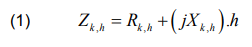
where Rk,h and Xk,h are the resistance and reactance of the transmission line k at hth harmonics. Similarly, the transmission line admittance matrix of the hth harmonics is a reciprocal of the line impedance which is generated separately for any order of harmonics.

Harmonics modelling of renewable energy components
In this study, the harmonic sources are modelled as current injections and these sources are wind turbines [21], PV modules and power electronic inverter as presented in Fig. 1. The sum of individual harmonic current at each source determines the current harmonics at the point of common coupling (PCC). The sum total of the harmonic currents at the PCC is always less than the quantity of harmonic emissions from those components. This is referred to as harmonic aggregation and it diverges between different harmonic contributions based on different harmonic buses [10].
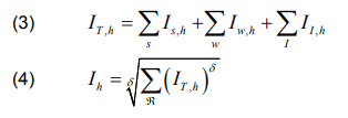
where Is,h , Iw,h and II,h are the current harmonics for solar, wind and HVDC link, Ih is the aggregation of current harmonics, ℜ is the number of harmonic sources available, δ is the aggregation summation component and the values are δ = 1 for h < 5 , δ = 1.4 for 5≤ h ≤10 and δ = 2 for h > 10 .
Harmonic state estimation on a transmission line
The harmonics current and voltage are characterized with many undesired problems such as overheating and overvoltage on the transmission lines [3]. The state estimation of harmonic problems possesses a nonlinearity structure owing to the magnitude and phase components of the harmonics and this can be resolved using either conventional or optimization methods [22]-[24].

Harmonic current
The current and voltage harmonic contributions from RES components are magnified by the resonance which multiply the harmonics quantity that occur on the transmission line. The current harmonic flowing on the transmission line is a function of the voltage harmonics at the buses and the harmonic admittance.
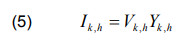
where Vk,h and Yk,h represent the harmonic voltage and admittance on the transmission line.
Harmonic power flow
The harmonic power flow is determined based on the solution provided by the set of linear equations. This is usually done to ascertain the resonant magnitude at each bus.
where and represent the harmonic voltage and admittance at each bus.
Harmonic power loss
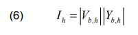
The harmonic sources are represented as current injections. Therefore, in order to compute the harmonic power loss at each bus, the harmonics magnitudes and phase angles are considered, which are characterized by random variables.

where Vb,h and Yb,h represent the harmonic voltage and current at each bus; and is the phase angle difference at each bus.
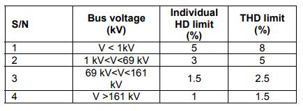
Total harmonic distortion
The voltage total harmonic distortion (THDv) is the harmonics contribution of individual harmonic components at each bus of the system. In accordance to IEEE 519-1992 standard, the THDv must not exceed its maximum permissible limit (THDvmax).
Table 2. International standard for total harmonic distortion for different voltage levels [25].
Simulation of the study system
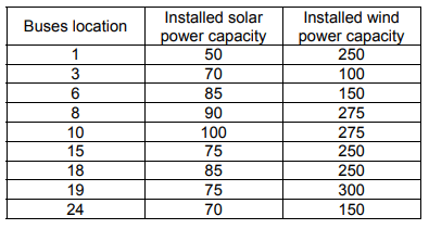
Two case studies were considered for modelling and the simulation has been performed using Electrical Transient Analyzer Program (ETAP) 12.6.0 software package. The case studies are the undistorted IEEE 6-bus and 24-bus test systems. The grid modelling for the 6-bus system as shown in Fig. 2 has four solar and wind farms with installed capacity of 60 MW and 900 MW respectively. Similarly, the 24-bus system has shown in Fig. 3 contains nine solar farms and wind parks with capacity of 700 MW and 2000 MW respectively.
Wind turbines
In this study, a doubly-Fed Induction Generator (DFIG) was used for wind turbine with rated power of 5 MW. In order to obtain both the magnitude and phase angle of the current harmonics, DFIG is modelled as a current source with parameters such as rotor resistance, stator resistance, reactance and magnetizing reactance valued at 0.0389 pu, 0.005 pu, 0.085 pu and 7.089 pu respectively. The generated power from the wind farm is sent to the wind farm transformers of voltage of 22 kV, which later fed the HVDC link.
Table 3. Installed capacity of renewable energy sources for 6-bus system.
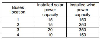
Table 4. Installed capacity of renewable energy sources for 24-bus system.
Solar PV panels
Here, the PV array are formed from the series and parallel formation of the solar PV panels in order to obtain the desirable output current and voltage. The PV rated capacity is 550 kW with power factor close to unity. The AC rated voltage and the input DC voltage are 400 V and 600 V respectively. The power output of solar PV farm is also connected to the transformer of 22 kV and its fed into the HVDC link.
Cables
This study considered offshore renewable energy sources because of easy accessibility of adequate wind speed. The cables in between turbines and PV arrays are modelled as parameters and the cables for transmitting power to the grid is modelled as distributed parameters. The length from the offshore to the grid 50 km and the length in between turbines is 1 km. The cables series resistance, reactance and susceptance are 0.063 Ω/km, 0.192 Ω/km and 0.06 mS/km respectively.
HVDC link
Here, a Voltage Source Converter HVDC transmission system is used and it consists of converter (rectifier and inverter), transformers, phase reactor, DC cables, DC capacitors and breakers. The values of the parameters used for this study are as obtained in [26]. A closed loop control is employed for the converter station and the PV and wind generating stations are controlled by stationed AC voltage. The reference value for the PV and wind farms as well as converter station is set to 500 MW. The AC and DC reference voltage values are 150 kV and 300 kV respectively.
Simulation results and discussion
The Garver’s 6-bus and IEEE 24-bus test systems are adopted in the harmonic estimation and are applied to simulate both the RES and power system components. In this study, harmonic analysis has been performed for the emission emanating from wind turbines, PV arrays and HVDC links spreading through the PCC and into the grid and consumers domain.
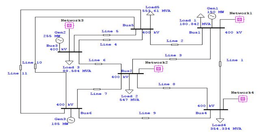
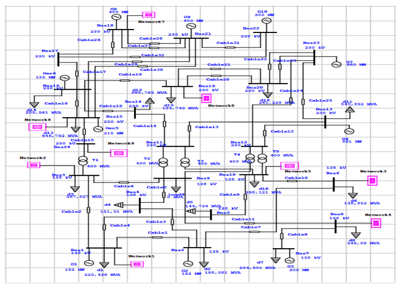
Table 5. Individual and total harmonic distortion for voltage in 6-bus system

Table 6. Individual and total harmonic distortion for voltage in 24-bus system

The findings of this study are presented in Tables 5-8. The individual and total harmonic emissions from the harmonic sources into the grid buses for 6-bus and 24-bus test systems are presented in Tables 5 and 6 respectively. From 6-bus system, it can be observed that the THD ranges from 6.88% to 10.82%. This is an indication that harmonic contributions at each bus exceeded the recommended standard limits as given in Table 2. The wind turbines, PV arrays and HVDC links contributes significant harmonics to the grid. Also, the harmonic level is relatively high in bus 5 and 6 as compared to other buses. This is an indication that the transmission system experience high resonance as a result of magnified harmonics at buses 5 and 6. The harmonics emanating from the RES components propagates to the nearest buses and this propagation is the same to all buses without RES components at odd orders of harmonics. The main reason is because of the wind and Solar PV power are more dominant in the grid.

Table 6 shows the individual voltage harmonics and total harmonic distortions for 24-bus test system. It is observed that there is significant harmonic violation at all the buses for both the individual and total harmonic distortions. These are odd harmonics which violate the recommended standard limits as specified by IEEE. Figures 4 and 5 show harmonic power loss along each bus for Garver 6-bus and 24-bus test systems. The harmonic power losses are computed from the proposed analytical method which are calculated from harmonic contributions of individual harmonics at each bus. These harmonic power losses are induced by the harmonic contributions from wind turbines, PV arrays and HVDC links. These values reflect the relative influence of harmonic distortions on power losses.
From Tables 7 and 8, it can be observed that the distortions at each bus has significant impact on the power system characteristics of Garver bus and 24-bus systems respectively. The background harmonics results in significant decrease in power factor and increase in voltage drop at each bus. The levels of power factors are much lower, hence, resulting in an increase in voltage drop across the buses. The power system characteristics are heavily impacted by the high frequency harmonic emissions from the wind and solar PV parks into the grid. The resonance in the wind and solar PV parks occurs due to the inductance and capacitance of the transformers and transmission cables respectively. Hence, the buses without RES experience some level of resonance frequency owing to the distance between them and the parks.
Table 7. Power system characteristics for a 6-bus system

Table 8. Power system characteristics for a 24-bus system.

Conclusion
This paper presents a study on harmonic distributions in a large-scale renewable energy integrated system. In this study, analytical method is proposed for estimating harmonic power loss and power flow at the bus and transmission network. Based on this method, the harmonic power loss and power flow can be effectively computed from the individual and total harmonic distortions as obtained from each bus. The characteristics of harmonic propagation patterns are investigated based on harmonic contributions from wind and solar PV parks. The effectiveness of the developed approach is tested on IEEE 6-bus and 24-bus test systems. Simulation results show that the individual harmonic distortions and total harmonic distortions are aboved the recommended limit at the buses owing to the emissions originating from the solar and wind parks into the grid. These harmonics has significant impact on the power losses and power system characteristics.
REFERENCES
[1] Gbadamosi S.L., Nwulu, N.I., A multi-period composite generation and transmission expansion planning model incorporating renewable energy sources and demand response. Sustain. Energy Technol. Assessments, 2020, vol.39, p. 100726.
[2] Nwulu N.I., Fahrioglu M., Investigating a ranking of loads in avoiding potential power system outages, Przeglad Elektrotechniczny, Volume 88, Issue 11 A, 2012.
[3] Gbadamosi S.L., Melodi A.O., Harmonic distortion from induction furnace loads in a steel production plant. Int. Inst. Sci. Technol. Educ., 2013, vol. 3, no. 10, pp. 8–17.
[4] Kutt L., Saarijarvi E., Lehtonen M., Molder H., Niitsoo J., Estimating the harmonic distortions in a distribution network supplying EV charging load using practical source data – Case example. IEEE Power Energy Soc. Gen. Meet., 2014, vol. 2014, pp. 4–8.
[5] Wang S., Liu X., Wang K., Wu L., Zhang Y., Tracing harmonic contributions of multiple distributed generations in distribution systems with uncertainty. Int. J. Electr. Power Energy Syst., 2018, vol. 95, pp. 585–591.
[6] Ray P.K., Subudhi B., Neuro-evolutionary approaches to power system harmonics estimation. Int. J. Electr. Power Energy Syst., 2015, vol. 64, pp. 212–220.
[7] Gbadamosi S. L., Melodi A.O., EFFECTS OF STEEL PLANTS WITH THREE-PHASE INDUCTION FURNACES ON POWER DISTRIBUTION QUALITY OF THE EXISTING 33 kV NETWORK IN NIGERIA. Adv. Sci. Technol. Res. J., 2015, vol.9, no. 27, pp. 1–10.
[8] Bollen M. H. J., Yang K., Harmonic aspects of wind power integration. J. Mod. Power Syst. Clean Energy, 2013, vol. 1, no.1, pp. 14–21.
[9] Malik M., Sharma P.R., A scheme for reduction in harmonics and establish the stability of hybrid system connected in grid. Ain Shams Eng. J., 2020, pp. 1–8.
[10] Bečirović V., Pavić I., Filipović-Grčić, B. Sensitivity analysis of method for harmonic state estimation in the power system. Electr. Power Syst. Res., 2018, vol. 154, pp. 515–527.
[11] Papathanassiou S. A., Papadopoulos M. P., Harmonic analysis in a power system with wind generation. IEEE Trans. Power Deliv., 2006, vol. 21, no. 4, pp. 2006–2016.
[12] Bagheri P., Xu W., Ding T., A Distributed Filtering Scheme to Mitigate Harmonics in Residential. IEEE Trans. Power Deliv., 2016, vol. 31, no. 2, pp. 648–656.
[13] Sakar S., Balci M. E., Abdel S. H. E., Zobaa A. F., Integration of large- scale PV plants in non-sinusoidal environment: Considerations on hosting capacity and harmonic distortion limits. Renew. Sustain. Energy Rev., 2018, vol. 82, 176–186.
[14] Munir S., Li Y. W., Compensation Scheme Using Power Electronics Interfaced DGs. IEEE Trans. Smart Grid, 2016, vol.7, no. 3, pp. 1191–1203.
[15] Cagri I., Karatepe E., Boztepe M., Impact of harmonic limits on PV penetration levels in unbalanced distribution networks considering load and irradiance uncertainty. Electr. Power Energy Syst., 2020, vol. 118, p. 105780.
[16] Abdelsalam A. A., El-saadany E. F., Probabilistic approach for optimal planning of distributed generators with controlling harmonic distortions. IET Gener. Transm. Distrib., 2013, vol. 7, no. 10, pp. 1105–1115.
[17] Mazin H. E., Xu W., Huang B., Determining the Harmonic
Impacts of Multiple Harmonic-Producing Loads. IEEE Trans.
Power Deliv., 2011, vol. 26, no. 2, pp. 1187–1195.
[18] Garanayak P., Panda G., Ray P. K., Harmonic estimation using RLS algorithm and elimination with improved current control technique based SAPF in a distribution network. Int. J. Electr. Power Energy Syst., 2015, vol. 73, pp. 209–217.
[19] Ujile A., Ding Z. A., dynamic approach to identification of multiple harmonic sources in power distribution systems. Int. J. Electr. Power Energy Syst., 2016, vol. 81, pp. 175–183.
[20] Puchalapalli S., Pindoriya N. M., Harmonics assessment for modern domestic and commercial loads: A survey. Int. Conf. Emerg. Trends Electr. Electron. Sustain. Energy Syst. ICETEESES 2016, pp. 120–125.
[21] Rajan , K. Dhayalini , S. Sathiyamoorthy, Genetic Algorithm for
the coordination of wind thermal dispatch, PRZEGLĄD ELEKTROTECHNICZNY, ISSN 0033-2097, R. 90 NR 4/2014
[22] Kabalci Y., Kockanat S., Kabalci E. A., modified ABC algorithm approach for power system harmonic estimation problems. Electr. Power Syst. Res., 2018, vol. 154, pp. 160–173.
[23] H. Bouzeboudja, M. Maamri , M. Tandjaoui, The Use of Grey Wolf Optimizer (GWO) for Solving the Economic Dispatch Problems based on Renewable Energy in Algeria A case study of “Naama Site”, PRZEGLĄD ELEKTROTECHNICZNY, ISSN 0033-2097, R. 95 NR 6/2019.
[24] W. Khamsen, C. Takeang, Hybrid of Lamda and Bee Colony Optimization for Solving Economic Dispatch, PRZEGLĄD ELEKTROTECHNICZNY, ISSN 0033-2097, R. 92 NR 9/2016
[25] Aurasopon , W. Khamsen, An improved local search involving bee colony optimization using lambda iteration combined with a golden section search method to solve an economic dispatch problem, PRZEGLĄD ELEKTROTECHNICZNY, ISSN 0033-2097, R. 95 NR 1/201
[26] Thi N., Yen H., Hongkun C., Ngoc L., Study on VSC-HVDC grid topology of offshore wind farms. Cluster Comput., 2018, vol. 1.
Authors: Dr. Saheed Lekan Gbadamosi, Dept. of Electrical & Electronics Engineering Science, University of Johannebsurg, Johannesburg, Auckland Park Campus, South Africa. E-mail: gbadamosiadeolu@gmail.com; Prof. Nnamdi. I Nwulu, Dept. of Electrical & Electronics Engineering Science, University of Johannebsurg, Johannesburg, Uckland Park Campus, South Africa. E-mail: nnwulu@uj.ac.za; Dr. O.M. Babatunde, Dept. of Electrical & Electronics Engineering, University of Lagos, Nigeria. E-mail: olubayobabatunde@gmail.com.
Source & Publisher Item Identifier: PRZEGLĄD ELEKTROTECHNICZNY, ISSN 0033-2097, R. 97 NR 4/2021. doi:10.15199/48.2021.04.26
